New Hydraulic Control Technologies for Improving the Energy Efficiency of the Hydraulic System of Agricultural Tractors and Their Implements
Xin Tian1,*, Xiaofan Guo1, Patrick Stump1, Giovanni Dessy1, Andrea Vacca1, Stefano Fiorati2 and Francesco Pintore2
1Maha Fluid Power Research Center, Purdue University, West Lafayette, IN, USA
2CNH Industrial S.p.A, Modena, Italy
E-mail: xin.tian@cnh.com
*Corresponding Author
Received 08 June 2024; Accepted 12 June 2024
Abstract
This paper describes two alternative methods to achieve the goal of reducing the fuel consumption of the high-pressure hydraulic control system of agricultural tractors and their implements. The first approach consists of a re-visitation of the basic load sensing (LS) technology used to power the hydraulic remotes. Namely, the metering regulations proper of a LS system is shifted from the tractor remote valves to the implement control valves. The second approach instead converts the hydraulic supply from a flow-based control logic (like in the LS system) to a pressure-based control. In different ways, both methods allow eliminating the conflicts existing between the tractor control valves and the implement ones, which cause excessive pressurization of the supply pumps and therefore high throttling losses.
The proposed methods are properly analyzed in simulation, and then tested considering reference of a 390 hp tractor and a 16-row planter. The results show a high improvement in energy performance for both the proposed solutions. With respect to the commercial system considered as the baseline, both solutions allow increasing the energy efficiency by more than 38%, with variations that depend on the operating conditions.
Keywords: Load-sensing, agricultural tractors, implements, efficiency, energy.
1 Introduction
Fuel consumption of agricultural machinery is a very sensitive topic from the operating costs and environmental impact points of view. For this reason, agricultural tractors usually adopt high energy-efficient power transmission technologies, such as advanced hydromechanical transmissions [1]. One critical energy consumer in the tractor system is the high-pressure hydraulic system that governs the in-tractor functions (such as steering, hitches, brakes, and suspensions) as well as the hydraulic remotes that power agricultural implements. Experimental activity performed by the authors quantified the overall energy efficiency of such a hydraulic system is as low as 20%, when the tractor powers a high-energy demand implement, such as a planter. Therefore, there are opportunities for re-designing this hydraulic control system for achieving higher energy efficiency while retaining the dynamic requirements of the controlled functions.
Typically, the hydraulic control architecture for this high-pressure system is the well-known load sensing (LS) architecture, as shown in Figure 1. This architecture uses local pressure compensators (LPC) before the proportional directional control valves (PDCV) to allow independent control of the attached loads (pre-compensated LS architecture). The basic theory of LS system can be found in several literature sources, such as [2].
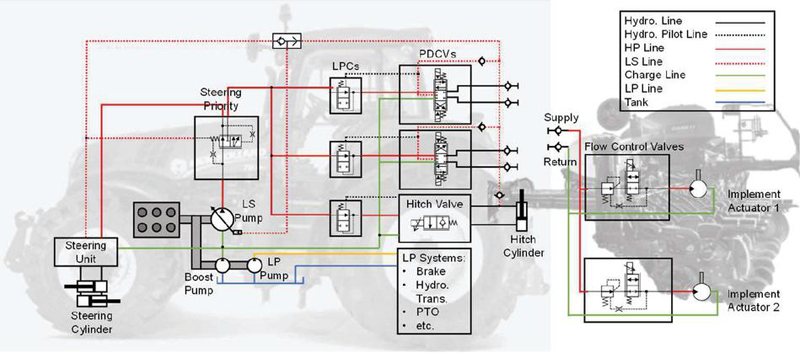
Figure 1 Tractor pre-compensated LS hydraulic system (left) and implement hydraulic system (right).
When an agricultural implement is connected to a tractor, multiple hydraulic functions can be connected to a remote line. With no ability to control the tractor hydraulics directly, the hydraulic circuit of the implement usually includes additional flow control valves to allow independent regulations of each hydraulic function, as indicated in Figure 1 on the implement side. This design strategy allows compatibility between different implements and tractors for all applications. In this case, the tractor hydraulics may be set to be continuously active, at full flow command, to assure immediate access to hydraulic power of the auxiliary valves in the implement, which actually determine the effective flow in the system. The issue occurs that this configuration of redundant valves, with only the downstream valves in the circuit effectively controlling the flow, result in an excessive throttle of the working fluid, which leads to significant power losses and oil heating. In more detail, during the operation of the system, the LS pump will pressure saturate, reaching its maximum allowable pressure, due to the inability of meeting the flow request of the LS valve (i.e. the hydraulic remote valve) which is set to full command.
The excessive system pressurization causes the above-mentioned power loss and increases the cooling requirements of the working fluid. To reduce this inefficiency, better integration of the hydraulic control system of the tractors and implements is required.
Related work reported in the literature tackles the potential for improving the efficiency of tractor-implement systems either from the selection of the ground-engaging tools [3] or general control of the tractor-implement-automation ISOBUS connection [4–6]. Only few papers address the issue of the excessive energy loss due to the regulation conflict between the hydraulic control valves in such LS architecture. This paper analyzes and compares two different solutions to tackle this problem. Hydraulic Load-Sensing (HLS) solution is through re-configuring the system layout to allow the LS pressure sensed directly from the functions on the implement side instead of the tractor remote outlets, thus avoiding the occurrence of pressure saturation conditions. This solution might negatively affect the system dynamic behavior but avoids the LS pump to reach pressure saturation. The second solution is the Intelligent Pressure Saturation Control (IPSC) solution that actively control the pump delivery pressure to minimize the power loss that occurs when the fluid is throttled through control valves, still achieving the desired system requirements. The IPSC was first introduced by the authors’ team in the paper [7]. The solutions were first studied on a high-fidelity model developed for a reference tractor and implement (a planter), followed by the experimental tests on the same vehicles for verification of the energy benefits with respect to the original system configuration.
2 Proposed Solutions
As shown in Figure 2, two of the tractor PDCVs, which include variable openings to the remote functions, are represented as variable orifices, without considering the typical bidirectional positions (i.e. extension and retraction) of the valve. The tractor LS system ensures that the pump delivery pressure is a margin pressure higher than the dominant function pressure, which is equal to :
| (1) |
where is the pump delivery pressure, refers to the load-sensing pressure and is the pump margin setting.
However, when the tractor is connected to the implement, there are more flow control valves controlling the flow rate in the hydraulic line. The tractor flow control valve (hydraulic remote) is set to maximum opening to allow the implement to achieve local control of the function flow rates. The compensator of the implement flow control valve (for example component (i)), closes until the flow setpoint is reached at the function hydro-fcn1. This can occur only when the absolute pressure limiter of the pump limits the pump pressure to . Due to the lower flow with respect to the commanded flow to the LS valve (component (g)), the flow regulator at the LS pump will be overridden by the pressure limiter. Therefore, the LS pump needs to operate at its maximum pressure (pressure saturation), voiding the advantages of the LS regulation principle, and leading to significant power loss across the flow control valves on the planter side. Note that with multiple flow control valves in parallel, one compensator in the implement side is sufficient to create the pressure saturation condition.
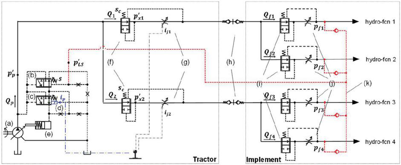
Figure 2 HLS solution (red) and IPSC solution (blue) proposed on the reference machine: (a) hydraulic pump supply; (b) pump flow regulator; (c) pump pressure compensator; (d) solenoid control signal; (e) control piston; (f) tractor LPCs; (g) tractor PDCVs; (h) quick couplers; (i) implement LPCs; (j) implement PDCVs; (k) LS signal line.
The two proposed solutions are depicted in the simplified circuit with different colors in Figure 2. The HLS solution treats the tractor and implement system as a whole and has the pump LS signal sensed directly from the implement functions. For this solution, the pump margin should likely be increased to a higher level than the original settings (). This is to account for the increased throttling losses that occur between the pump outlet and the local compensators at the implement, with respect to the losses that occur between the pump and the remote valve. The overall tractor-implement system now still follows the LS law as in Equation (1), delivering , where , and refers to the pressure of each function.
Moreover, the IPSC solution leverages the above-described feature of the commercial solution where the LS pump saturates in pressure and operates as a constant pressure source. The IPSC solution dynamically adjusts the pressure cut-off setting of the pump to reduce the pressure losses without altering the functioning of the system. Conceptually, the IPSC treats the supply pump as a pressure source as opposed to a flow source as it should be in a LS system. As shown in Figure 2, the solenoid signal applied on the spring sides of the pressure compensator regulates the pump delivery pressure to , which is just sufficient to meet the function power requirements. Now the implement can still treat the tractor as a pressure source, but the supply pressure level adapts to the needs of the actuator.
Figure 3 demonstrates the benefits of the HLS and IPSC solutions through a power plot. The pump delivers the maximum pressure for the baseline conditions, whereas the pump delivers , a higher fixed margin pressure higher than the highest function pressure under the HLS solution. Beyond this, the IPSC solution allows the pressure difference between the highest function pressure and the pump delivery pressure to vary under different flow rate requests, further reducing the power reduction as shaded in the right of the plot. For consistency, the difference between the new and highest loading condition (), for this case, is defined as the equivalent new pump margin, , as in:
| (2) |
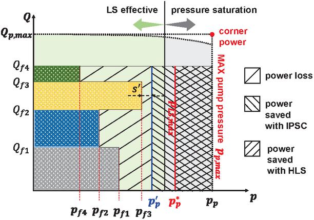
Figure 3 Solution effectiveness and system model validation results.
3 Reference Machine and Lumped-Parameter Model
This study considers the hydraulic circuit of a New Holland Cash Crop High tractor connected with a Case IH 16 row EarlyRiser 2150 planter as a reference for both model development, validation, together with experimental tests for proof of effectiveness. Figure 4 depicts the reference hydraulic circuits including the main components and actuators. The figure details the tractor supply unit, the tractor remote control valves, the planter local flow control valves, and three high-pressure functions of the planter that are frequently used during operations including the bulk fill fan system, the vacuum system, and the alternator system. The flow is provided by the tractor to the functions side through two electro-hydraulic remote (EHR) control valves, each controls the flow in the pre-compensated manner with a LPC before the 4/5 electrohydraulic PDCV, and a pair of lock check valves for retraction (R) and extension (E) directions of the actuations. The bulk fill fan system is supplied by EHR1 while the EHR2 supplies alternator and vacuum systems.
The three main functions taken into consideration are each composed of proportional flow control valves, gear motors controlled with feedback controllers, and loadings from the systems. Table 1 summarizes the information regarding their controller type and loading conditions.
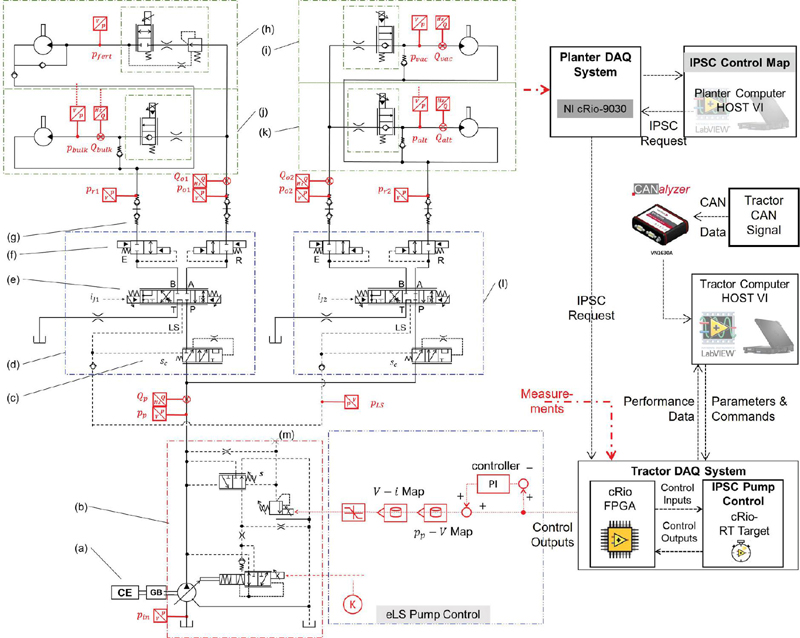
Figure 4 Reference machine with the DAQ system, both baseline and solution implemented: (a) combustion engine; (b) eLS pump; (c) LPC; (d) EHR1; (e) main spool; (f) lock check valve (E and R); (g) quick coupler; (h) fertilizer system; (i) vacuum system; (j) buk fill fan system; (k) alternator system; (l) EHR2; (m) pump load sensing port (HLS: connected to the load sensing pilot line, IPSC: blocked).
Table 1 Planter system components and control
| Bulk Fill Fan System | Alternator System | Vacuum System | |
| Motor rated displacement | 6.5 cc | 6.0 cc | 6.5 cc |
| Feedback control logic | Speed feedback control | Pressure feedback control | |
| Controller type | PI controller | ||
| System load type | Centrifugal pump | Generator | Centrifugal pump |
The baseline high-pressure hydraulic system of the reference tractor, including the LS pump and the EHR valves, was already carefully studied by the same research team through a combination method of simulations and experiments [8–10]. These cited references describe the tractor model developed via a lumped-parameter approach, considering interactions among both the hydraulic and mechanical domains. To capture the complete behaviour of the reference machine, the planter systems as well as a thermal engine model have also been developed. For brevity, this paper illustrates only the planter function to highlight the modelling approach.
As shown in Figure 5, the model describes the block interactions between the hydraulic motor, the hydraulic control valves, the hydraulic lines, the system load simulator, and the system controller for each planter function. The PI controllers in the bulk and the alternator systems assure accurate and fast speed tracking of the motor compared to the reference speed command.
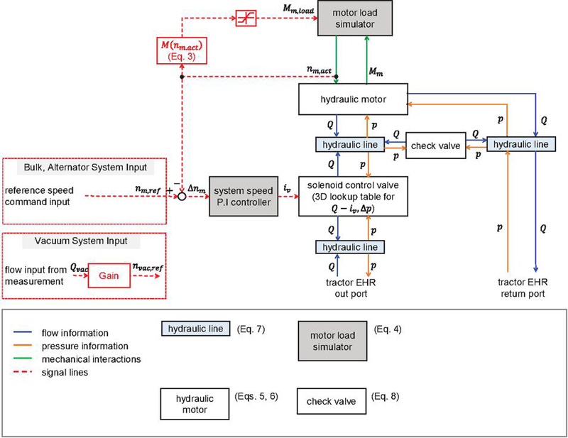
Figure 5 Modeling block diagram for planter functions.
The loads on the motors are all generated by the fitting functions that have been empirically validated describing the relationship between the motor speed and actual load torque (Equations (3) and (4)). The hydraulic motors embed a constant efficiency to predict the effective flow and torque provided by Equations (5) and (6).
| (3) | |
| (4) | |
| (5) | |
| (6) |
where is the moment of inertia, is the coefficient of viscous friction.
The displacements of the solenoid control valves in the three systems are controlled by the electronic command input . With the valve performance 3D curve embedded, which is provided by the manufacturer, the flow rates through the valve can be decided under current displacement and pressure drop effects.
Besides, the pressure build-up equations are used to decide the pressure levels in the hydraulic lines (Equation (7)) and the flow rates across the check valves are expressed in (Equation (8)).
| (7) | |
| (8) |
The three planter functions are assembled with the tractor model through quick couplers, which are modeled with fixed orifices, in software Simcenter Amesim as shown in Figure 6. Such a model of the reference machine will be used to study the implementation and the effectiveness of the proposed solutions.
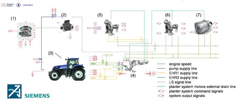
Figure 6 General layout of the complete system model in Simcenter Amesim grouped in supercomponents: (1) combustion engine; (2) pressure and flow compensated LS pump; (3) tractor remote control valves; (4) quick couplers; (5) bulk fill fan system; (6) vacuum system; (7) alternator system.
4 Solution Implementation
The reference machine was instrumented with a total of 11 pressure sensors and 6 flow meters to experimentally measure the energy flow on the mentioned three main functions and a complete data acquisition system has been set up to collect the system performance data as indicated again in Figure 4. More details on the data acquisition system setup can be found in [10]. For easier adoption of both proposed solutions on the reference machines, an electronic controlled LS pump from Bosch Rexroth, which replicates the same features of the baseline pump developed in [8], was adopted in the reference tractor whose output pressure can be controlled to vary steplessly with the input solenoid command.
The HLS solution is implemented by reconnecting the LS pilot line to the planter side following the indication in Figure 2 (label 11), to have the pump sense the pressure in the LS line and be controlled in the traditional hydro-mechanical manner.
For the IPSC solution, the key to pressure control of the IPSC solution is to determine the lowest but sufficient pump margin needed to ensure the system performance under different operating conditions. For this reason, the numerical model built (Figure 6) was used to determine the map, which turns out to be a third-order polynomial fit curve:
| (9) |
The eLS pump is now controlled in an electronic way by blocking the LS port (indicated in Figure 4, label 13) and a PI controller is equipped to meet the desired pump delivery , as represented as the eLS pump control block in Figure 4.
Echoing the control loop shown in Figure 4, the different load pressures from the planter side are collected by the DAQ system. The data get compared to determine the maximum function pressure to input to the IPSC map, and the optimal pump delivery pressure request is generated in the IPSC control LabVIEW code. The request from IPSC control gets sent over an analog channel to the tractor DAQ system pump control LabVIEW. The cRio FPGA block serves as a fast data transfer mechanism to transfer data from the digital signal to the actual pressure and flow reading values and pass that onto the real-time (RT) target block. The cRio RT target block receives both the IPSC request command from the planter DAQ and the measurement signals from FPGA and generates the control inputs to the pump’s pressure controller and sets full command to the displacement controller. The synchronization signals are sent between the two laptops to align data sets.
Table 2 System settings for different conditions
| System | Vehicle | Vacuum | Bulk Fill | Alternator |
| Condition | Speed [mph] | Fan [rpm] | Fan [rpm] | [rpm] |
| Normal | ||||
| Fast | ||||
| Maximum |

Figure 7 In-lab test of the solutions in Maha Fluid Power Research Center. (left: New Holland Cash Crop High tractor, right: Case IH 16 row EarlyRiser 2150 planter).
5 Results
5.1 Tractor-planter Laboratory Operations
Three different realistic planter operating conditions, namely Normal, Fast and Maximum, as summarized in Table 2, have been consolidated in the same cycle to study the proposed solutions’ effectiveness. As shown in Figure 7, the stationary experiments have been carried out in Maha Fluid Power Research Center at Purdue University on the reference machine. The difference between the conditions lies in different speed settings of the functions, with Normal and Fast being the representative settings of where the planter is working most frequently, the Maximum setting intends to draw out the boundary system conditions when all the functions are requiring most.
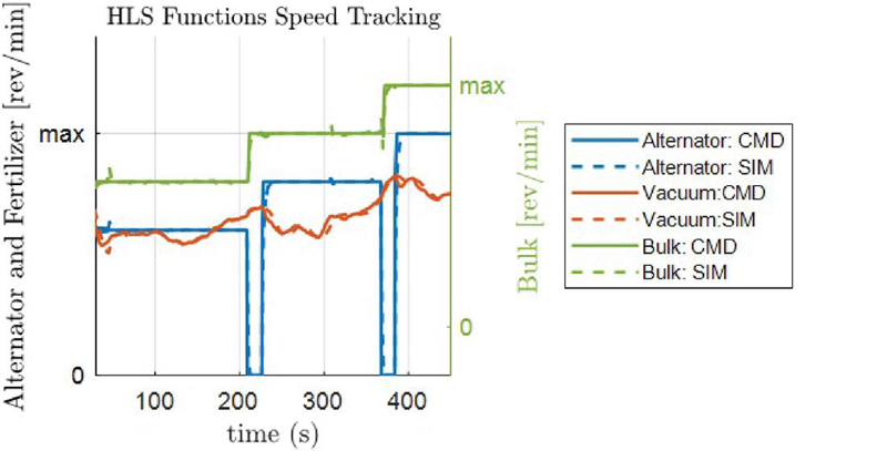
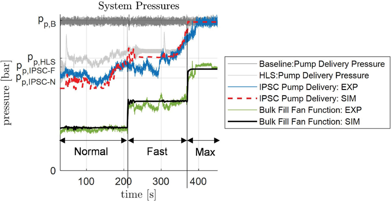
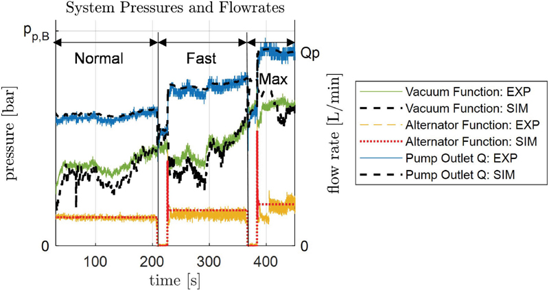
Figure 8 Solution effectiveness and system model validation results.
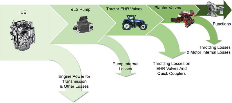
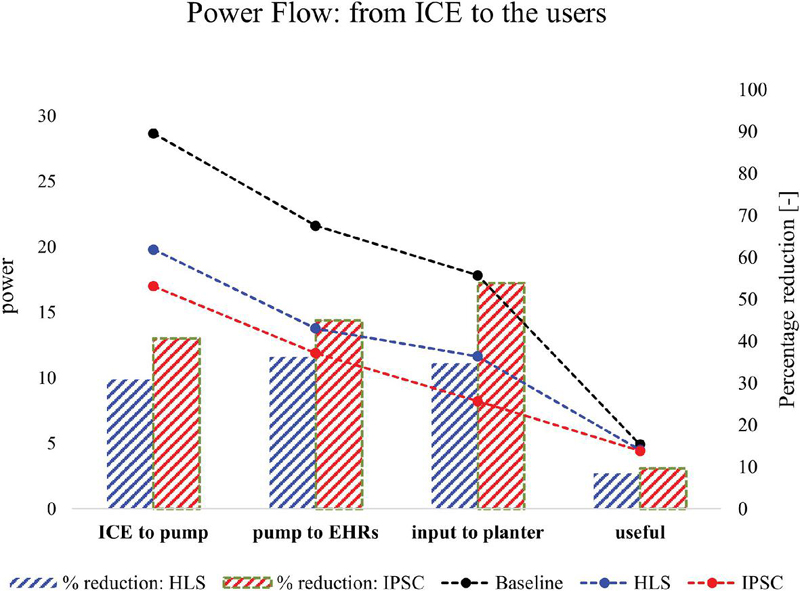
Figure 9 (a). system power flow description; (b). power dissipation comparisons.
As shown in Figure 8, the simulation results and the in-lab stationary test results are compared together for baseline, HLS and IPSC solutions are satisfying the same functional pressure and flow rate requirements. The system’s fast and accurate tracking for all the actuators (Figure 8(a)) indicates correct flow rate matchings between simulations and measurements for the HLS solution. An overall matching error for steady-state conditions is 5.4% for all system pressures and 1.8% for system flows, calculated from Equation (10), proving the high fidelity of the model developed. The pump supply pressure for the solutions varies to different levels with different conditions, both of which achieve a significant decrease compared to the baseline .
| (10) |
Power flow in the system takes such a path that, referring to Figure 9(a), the engine supplies both the transmission load and the hydraulic actuation power source, the eLS pump. After some internal losses due to pump efficiency, the power flows to the EHR valves inside the tractor and then supplies the planter system. Some power is lost due to throttling on the planter control valves while the left is doing the required work, referred to as useful power. The power flow indicated in Figure 9(b) summarizes that though the same useful power, the supply power at the pump shaft has been almost halved for IPSC solution with still a 30% reduction for HLS solution compared to the baseline.
Table 3 summarizes the system performance improvement under different steady-state conditions for both solutions compared to baseline. Overall, both of the solutions are showing great potential regarding system efficiency improvements and power saving. Especially, the IPSC solution contributes to the most often used conditions, normal and fast with an above 46% reduction in mechanical power consumption at the pump shaft and above 38% efficiency improvement, showing the great potential of fuel reduction benefit in the tractor-planter hydraulic system.
Table 3 Styles system performance comparisons for stationary tests: soybean
| Parameter | ||||
| Mechanical Supply | System | Improvement | ||
| Solution | Condition | Power Reduction | Efficiency [%] | |
| Baseline | Norm | – | 18.3 | – |
| Fast | – | 27.0 | – | |
| HLS | Norm | 38.3% | 23.4 | 27.9% |
| Fast | 18.6% | 28.3 | 04.6% | |
| IPSC | Norm | 46.2% | 29.8 | 38.7% |
| Fast | 25.8% | 34.5 | 21.6% |
5.2 In-field Operations
Last but not least, the Normal and Fast operating conditions for the tractor-planter system were tested within this research during the actual planting operation, with all of the seven functions activated. The reference vehicles were tested at Purdue Animal Science Research Center of Purdue University as shown in Figure 10.

Figure 10 In-field test of the solutions in Purdue University Farm.
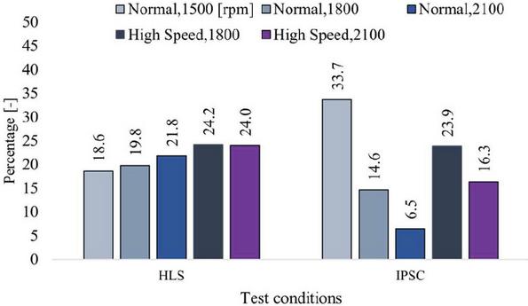
Figure 11 Field test results on HLS and IPSC power savings.
Figure 11 reports the percentage of savings on the hydraulic power supply for both solutions under five different cases, two running conditions driven by three different engine speeds. On average, the HLS solution contributes to 19.7% power reduction while IPSC contributes 20.6%. Contradictory as it seems to the in-lab results, it’s worth noting that during the field tests, instead of three, all of the seven planting functions are activated during the operations. In particular, the hydraulic down pressure cylinders are introducing a new highest pressure in the system. As a result the pump delivery pressure is driven to a higher level than that of the in-lab tests, resulting in lower savings in general.
Moreover, it is worth noting that the results reported here are not indicating a clear trend that the IPSC solution is always more efficient than HLS. The reason for this is mainly due to the fact that dynamically the HLS solution is not tracking the cylinder pressure well due to possible reasons include not enough pump margin, long LS line with large capacitance. And this leads to a lower delivery pressure in the HLS solution and gives higher savings.
Still, despite the different settings from the in-lab environments, the results from the field test prove the compatibility and effectiveness of the HLS and IPSC solutions on the agricultural tractor and planter systems.
6 Conclusion
This paper proposed two different solutions targeting the inefficiency issue inside the tractor with planter system. The first HLS solution makes sure the advantages of load sensing architecture still hold but get the pump away from pressure saturation by directly connecting the pilot line from the functions. The IPSC solution is based on an impressed pressure methodology as opposed to the traditional flow control methodology by controlling the pump supply pressure just enough to meet all the system requirements. A combined approach of simulation and experiments have been followed to study the effectiveness of the solutions. Both in-lab stationary tests and field tests have been carried out on the reference machine, achieving up to 46% mechanical power reduction on the pump supply shaft. In general, the IPSC solution brings more savings than the HLS solution under the most representative duty cycles and shows more potential for a commercial adoption.
Acknowledgment
The authors would like to acknowledge the active support of this research from Simcenter Amesim platform provided by Siemens.
References
[1] A. MacOr and A. Rossetti, “Optimization of hydro-mechanical power split transmissions,” Mech. Mach. Theory, vol. 46, no. 12, pp. 1901–1919, 2011.
[2] A. Vacca and G. Franzoni, Hydraulic Fluid Power: Fundamentals, Applications, and Circuit Design, 1st ed. John Wiley & Sons, Inc, 2021.
[3] Clarence E. Johnson, Eddie C. Burt, John E. Morrison, Alvin C. Bailey, and Thomas R. Way, “Energy Reduction in Sweep Tillage Systems,” 2001 ASAE Annual Meeting (p. 1), vol. 0300, American Society of Agricultural and Biological Engineers, pp. 1–10, 2001.
[4] R. Hoy, “Agricultural Industry Advanced Vehicle Technology: Benchmark Study for Reduction in Petroleum Use,” Biol. Syst. Eng., no. September, pp. 1–64, 2014.
[5] K. J. Stoss, J. Sobotzik, B. Shi, and E. R. Kreis, “Tractor Power for Implement Operation – Mechanical, Hydraulic, and Electrical: An Overview,” Agric. Equip. Technol. Conf., pp. 1–25, 2013.
[6] A. J. Scarlett, “Integrated Control of Agricultural Tractors and Implements: A Review of Potential Opportunities Relating to Cultivation and Crop Establishment Machinery,” Comput. Electron. Agric., vol. 30, no. 1–3, pp. 167–191, 2001.
[7] X. Tian, X. Guo, P. Stump, A. Vacca, S. Fiorati, and F. Pintore, “A Pressure Control Method for Increasing the Energy Efficiency of the Hydraulic System Powering Agricultural Implements,” J. Dyn. Sys., Meas., no. (under review), 2022.
[8] X. Tian, J. C. Gomez, A. Vacca, S. Fiorati, and F. Pintore, “Analysis of Power Distribution in the Hydraulic Remote System of Agricultural Tractors Through Modelling and Simulations,” in Bath/ASME Symposium on Fluid Power and Motion Control, FPMC 2019, 2019.
[9] X. Tian, A. Vacca, S. Fiorati, and F. Pintore, “An Analysis of the Energy Consumption in the High-Pressure System of an Agricultural Tractor through Modeling and Experiment,” in 77th International Conference on Agricultural Engineering, LAND. TECHNIK AgEng, 2019, pp. 9–18.
[10] X. Tian, P. Stump, A. Vacca, S. Fiorati, and F. Pintore, “Power Saving Solutions for Pre-Compensated Load-Sensing Systems on Mobile Machines,” Trans. ASABE, vol. 64, no. 5, pp. 1435–1448, 2021.
Biographies

Xin Tian received her PhD degree in Mechanical Engineering from Purdue University where she focused on simulation and control of hydraulic systems in agricultural machines. Before that, she received her bachelor’s degree in Mechanical Engineering from Xi’an Jiaotong University in Xi’an, Shaanxi province, China. She is currently a system modelling engineer in CNH Industrial America LLC, design analysis and simulation team. Her work mainly focuses on simulation and control of hydraulic system for future product development of off-road vehicles.

Xiaofan Guo received the bachelor’s degree, master’s degree and PhD in mechanical engineering from Purdue University in 2015, 2017 and 2024 respectively. He is currently working as a Systems Engineer at the Bosch Rexroth Corp. His research areas include innovative hydraulic system design, modeling and control.

Patrick Stump is an electro-hydraulic controls engineer for CNH Industrial and a PhD candidate at Purdue University. He received his Bachelors of Mechanical Engineering at Marshall University before working as a research assistant for Professor Andrea Vacca at Purdue University where he received his master’s. His area of research is experimental work in energy-efficient hydraulic systems, which includes electronic load-sensing architectures, adaptive pump controls, and efficient systems integration.

Giovanni Dessy received his bachelor degree in Mechanical engineering from University of Cagliari in 2020. He then graduated Polytechnic of Turin in 2022, with his master’s in Mechatronic Engineering. During his master’s degree he worked on his thesis at the Maha Fluid power lab. Currently he is a PhD student at the Dynamic Legged System lab at the Istituto Italiano di Tecnologia(IIT). His area of research involves human-robot and robot-robot interaction and collaboration involving quadruped’s robot.

Andrea Vacca is the director of the Maha Fluid Power Research Center, the largest academic research center dedicated to fluid power research in the United States. His research focuses on several aspects of hydraulic control technology including new concepts to perform hydraulic actuations, new designs and modeling of positive displacement machines, electrification of fluid power systems, modeling of the properties of hydraulic fluids, reduction of noise emissions from hydraulic components. Dr. Vacca is author of about 200 technical papers, and of the textbook “Hydraulic Fluid Power”. He was awarded the 2019 Joseph Bramah Medal from the Institution of Mechanical Engineers for his contributions to global fluid power research, particularly related to gear pumps. He is also a fellow of the American Society of Mechanical Engineers (ASME).

Stefano Fiorati is Director of Innovation & Advanced Propulsion Systems at CNH. He is responsible for expanding alternative fuels, electrification and driveline technologies across the Company’s entire agriculture and construction product portfolio. Prior to this appointment, Mr. Fiorati was Manager of Tractor Innovation, Zero Emission & Advanced Drivetrain at CNH from 2021–2023 and Tractor Innovation from 2014–2021. In this previous role, he was technical project leader for the New Holland T6.140 Methane Powered tractor prototype and subsequent concepts, presented in 2015 and 2017 respectively. Mr. Fiorati started his professional career with CNH Industrial in 2011 as Mechanical Design Engineer within the Innovation department. He has a PhD in Mechanics of Machine awarded jointly by the University of Ferrara, Italy, and the Katholieke Universiteit Leuven, Belgium. He has a master’s degree in Mechanical Engineering from the University of Ferrara, Italy.

Francesco Pintore is Manager of High-Performance System Simulation at CNH. He is responsible for High Fidelity 0D/1D model development, looking on entire vehicle performance evaluation, interfacing and providing modeling support to multiple Teams across CNH. He is also responsible for interfacing Modeling Team with electrification, Hydraulics, Driveline and Powertrain Teams across the Company’s entire agriculture and construction product portfolio. He has a Ph.D. in High Mechanics and Automotive Design & Technology from University of Modena & Reggio Emilia, Italy. And a master’s degree in mechanical engineering from the University of University of Modena & Reggio Emilia, Italy. Mr. Pintore, started his professional career with CNH in 2010 as PhD Student, within Innovation Department. He joins Design Analysis & Simulation Team in 2015 as System Modeling Engineer, creating Hydraulic & Driveline High fidelity Model for a wide range of Vehicles.
International Journal of Fluid Power, Vol. 25_2, 203–224.
doi: 10.13052/ijfp1439-9776.2525
© 2024 River Publishers