Dimensioning Method of Pneumatic Cylinders Based on the Pneumatic End-cushion
Christian Reese Jimenez*, Olivier Reinertz and Katharina Schmitz
Institute for Fluid Power Drives and Systems (ifas), RWTH Aachen University, Campus-Boulevard 30, D-52074 Aachen, Germany
E-mail: christian.reese@ifas.rwth-aachen.de
*Corresponding Author
Received 24 July 2024; Accepted 16 July 2025
Abstract
This paper proposes a novel method for dimensioning pneumatic cylinders for motion tasks. It considers conventional downstream throttled pneumatic cylinders. The proposed approach is based on the maximal loading capacity of the end-cushion and the resulting formula for the dimensioning of the cylinder size has a simple algebraic structure. The method was experimentally validated showing great accuracy in estimating the motion time of optimally operated pneumatic cylinders.
Keywords: Pneumatics, pneumatic cylinder, sizing method, end cushion, energy efficiency.
1 Introduction and State of the Art
In pneumatic drives, the consumption of compressed air depends on the volume of the cylinder chambers, the dead volumes of the attached lines and pressure levels. Therefore, one of the simplest yet effective ways to reduce the energy consumption of pneumatic systems is by accurately sizing the cylinders for the intended task. Two main aspects need to be considered for an optimal drive sizing. The force of the drive must be sufficient to perform the motion, while the end-cushion’s ability to decelerate the moving mass to avoid excessive impact speed on the end stop must be guaranteed. However, in practice, drives are often oversized due to uncertainties about the robustness of the ideal drive size to successfully perform the task, leading to the excessive use of safety margins. Furthermore, there is a general lack of awareness concerning energy consumption and an overall poor understanding of the interactions between the motion task parameters regarding proper drive dimensioning. To address this challenge, various dimensioning approaches have been developed with the aim of simplifying the design process.
Common sizing methods for pneumatic actuators include empirical formulas [1] designed for simple force-based applications. For more complex motion tasks, manufacturers offer computer-based sizing tools [2, 3]. However, these “black box” approaches lack transparency regarding the interactions between different parameters relevant to the sizing task and are limited in their flexibility. Simulation-based sizing, recommended by various researchers [4–6], offers an alternative and can be integrated with optimization schemes to achieve optimal sizing. However, such models require a high degree of expert knowledge, and many parameters are not readily available. Therefore, experiments for parameter identification are often necessary. Furthermore, the intuitive understanding gained from such comprehensive models is limited.
A more analytical approach to cylinder sizing, proposed by Vigolo, is named operating point analysis [7]. This method involves deriving analytical expressions based on the governing differential equations of the actuator system, under the hypothesis of steady-state behavior. The method correlates a given external load force to the force capacity of a pneumatic actuator and an optimal ratio of force to cylinder diameter can be calculated. This approach was utilized to define the optimization task for a machine learning model, aimed at adjusting the supply pressure and downstream throttle online to operate the system at theoretical optimal conditions [8]. The main limitations of this sizing approach are that there is no closed algebraic equation that relates all system parameters to the required task. Furthermore, the end cushion is not considered. Therefore, this sizing approach is limited to dynamic force tasks, as the necessary damping of high moving masses at stroke end is neglected.
Rakova proposed a sizing method based on exergy analysis, which relates the supplied exergy to the required exergy for a given task [9, 10]. Furthermore, a sizing factor was introduced based on friction forces and the compression work in the end cushion. Boyko investigated a modified version of this approach, wherein the expansion exergy was neglected [10], since conventional pneumatic systems only utilize the hydrostatic part of the exergy. However, cylinders sized with this method were found to be undersized for motion tasks, as evidenced by the high impact kinetic energy on the end stop.
Doll proposed a heuristic method for dimensioning downstream throttled drives for motion tasks [11, 12], which has been widely adopted in academia [13–15]. The method relies on a dimensionless number called the ’pneumatic frequency ratio’, denoted as . This ratio relates the actuator dynamics, determined by an estimation of its eigenfrequency mid-stroke, to the required dynamics for the motion task, given by the desired transfer time. To validate the sizing method, a large number of dynamic simulations were carried out, which considered the pneumatic end-cushion in the modelling. The resulting algebraic equation encapsulates all the relevant parameters for sizing drives for motion tasks. However, a dependence of on the cylinder length exists [11], which implies a reduction of accuracy on longer cylinders. Doll recently proposed an extension of the eigenfrequency method to allow for the integration of external load forces, thus extending the applicability of this method [16].
This paper proposes a novel sizing method for motion tasks, which is derived from the characteristic behaviour of the pneumatic end-cushion. It achieves higher accuracy on the dimensioning of pneumatic cylinders than the eigenfrequency method proposed by Doll, while retaining the simple algebraic structure.
2 Analysis of the Pneumatic End Cushioning Dynamics
The main goal of this section is to contribute to the understanding of the main dynamics at play in pneumatic end-cushioning, as the novel design guideline targets to utilize the maximal loading capacity of the end-cushion. To achieve this, the optimal setting of the damping-throttle is first mathematically defined, based on adjustment guidelines provided by manufacturers and an intuitive system understanding. Later, a simple model is derived, which encapsulates the interactions between the main parameters.
2.1 Definition of the ideal pneumatic cushion setting
The proper adjustment of the end-cushion plays a key factor in reducing the impact energy at the end of the stroke, thus reducing noise, wear, and increasing the service life of pneumatic actuators and of the attached components. The adjustment is known to be a challenging task, especially for inexperienced personnel. For this reason, many manufacturers have provided adjustment guidelines [17–19] and even electronic adjustment tools [20].
The general adjustment advice can be summarized as follows: If the cylinder exhibits speed oscillations while decelerating, then the resistance of the damping-throttle is adjusted too high and should be reduced. The stepwise opening of the damping-throttle might result in higher impact speeds, until the optimal setting is found. A properly adjusted air cushion should result in a quick, smooth deceleration. Thus, not only is the end shock minimized, but the deceleration time is also greatly reduced. Further opening of the damping throttle beyond the optimal setting results in higher impact speeds, as the cylinder does not decelerate enough, which is often perceived as an increase in noise.
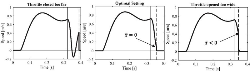
Figure 1 Adjustment ranges for the end-cushion. Cylinder size ø 32 mm, L 200mm, moving mass 10 kg.
From this empirically based adjustment advice, the optimal adjustment of the end-cushion is mathematically defined. The three possible setting ranges are depicted in Figure 1, where the cylinder speed is plotted over time. The speed curve was simulated using a non-linear pneumatic actuator model with heat exchange proposed by Ohligschläger [21] and implemented on MATLAB Simulink. The entry point in the end-cushion is characterized by the vertical full line and the reaching of the end-stop by a dashed line. Other than the adjustment of the damping-throttle no other parameters are varied. The optimal adjustment setting corresponds with the cylinder reaching the end-stop with zero acceleration, thus hitting the end-stop at the first local minimum in speed. Therefore, minimal impact speed is achieved, before the cylinder starts accelerating again and preventing any speed oscillations. If the damping-throttle is too wide open, the cylinder impacts while not fully decelerated and thus with a higher impact speed.
2.2 Simplified Model of the End-cushion Dynamics
Due to the importance of the end-cushion for the proper functioning and sizing of pneumatic actuators for motion tasks, significant efforts have been made in recent years to improve the accuracy of existing multidomain models. Notable examples include a more physics-based model of heat transfer, as well as improvements in friction parameterization proposed by Nazarov [22, 23]. Beater studied damping performance as a function of downstream and damping throttle adjustments, both through simulation and experimentation [24]. Beater’s results hint at similar relationships among the main parameters to those that will be presented in this section. Thus, accurate modelling approaches to simulate the system exist. However, a simple model to intuitively understand the system dynamics and algebraically summarize the key parameters is missing.
Some approaches to simplify the end-cushion are based on considering the maximal compression work in the cushioning chamber as a closed system (damping throttle being completely closed) [25]. Usually, a polytropic model is used for this. The resulting compression work can be equated to the maximal kinetic energy of the load that could be absorbed. However, as correctly pointed out by Beater, such approaches are static, and neglect pronounced oscillations caused by a wrong setting of the damping-throttle [24].
To better understand the system, the operating principle of the end-cushion will be briefly described with the help of Figure 2, for a cylinder in the extension stroke. The cylinder is characterized by the piston area , the rod-side area and the total cylinder length . During the mid-stroke movement (, the cylinder speed is regulated by the resistance of the downstream throttle. In steady state, this results in a constant speed proportional to the adjusted sonic conductance. This direct air path is closed by the damping piston when the cylinder enters the end cushion (. At this point, a division of the volumes takes place in the rod side, creating a damping volume with the effective area and the residual inner volume with the effective area . The outflowing air from the damping volume can only escape through the damping-throttle, which resistance is much higher. Consequently, the much slower speed setting provided by the damping-throttle becomes dominant. However, the compression of the air in the damping volume and the inertia of the mass result in a transient oscillatory response to the sudden change in speed setting. Therefore, the entry into the end-cushion may be considered as a speed step response of a nonlinear oscillatory system.
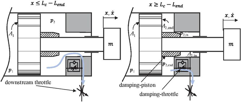
Figure 2 Principle of the pneumatic end-cushion.
This behavior will be approximated by the transient step response of an underdamped second-order system. The modeling approach is illustrated in Figure 3, where represents the entry speed in the end-cushion, is the travel time in the end-cushion and is the size of the step. The cylinder is considered at steady-state entering the end-cushion. Since a properly adjusted end-cushion is defined as ensuring that the cylinder reaches the end-stop with zero acceleration, the impact speed corresponds to the minimum at the first undershoot.
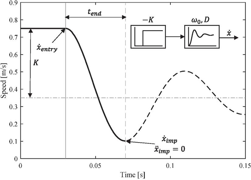
Figure 3 Linear model for the cylinder speed in a properly adjusted end-cushion.
The step response of a second-order system is a highly relevant subject in control theory and has been extensively studied mathematically. An analytical solution for the transient behavior of such a system in the time domain exists [26]. Based on this solution, the following equation for the cylinder speed in the end-cushion can be derived, where represents the damping ratio and denotes the damped frequency.
| (1) |
The damped frequency can be calculated based on the natural frequency and the damping ratio as follows:
| (2) |
Furthermore, the peak time , used to characterize the first over/undershoot in control theory [26] can be used to determine the travel time of the cylinder in the end-cushion :
| (3) |
By evaluating the speed at the end of the motion corresponding to the first undershoot, the relationship between the impact speed , the entry speed and can be derived.
| (4) |
For the cylinder to land on the end stop with zero acceleration, the travel distance from entry into the end-cushion to the first local speed minimum must match with the length of the end-cushion . This condition can be implemented by integrating the expression for the speed in Equation (1) over the travel time . Equation (5) shows the solution for such integral.
| (5) |
By incorporating Equation (4) in Equation (5) and rearranging the following algebraic formula relating the impact speed with the entry speed in the end-cushion results, where is a factor only depending on the damping ratio. It should be noted that, in this step, was eliminated, which corresponds to the magnitude of the change in the speed setting for the step response.
| (6) | |
| (7) |
For the model to be completed, it is necessary to parametrize the linear second order system with expressions for the natural frequency and the damping ratio . This will be achieved by linearizing a simplified model of the end-cushion dynamics. It should be noted that the dynamics in the end-cushion are in reality highly non-linear. The eigenfrequency specially is dependent on the strongly changing pressure and chamber volume. The hope is however to find a practical simple term for the eigenfrequency, which helps to approximate the real dynamics under different conditions when the air cushion is near its maximal loading capacity and properly adjusted.
The mechanical modelling results from Newton’s second law, which describes the forces acting on the mass . The friction force was split in a constant sliding friction and a viscous term proportional to . Equation (2.2) corresponds to the equation of motion in the end-cushion for the extending stroke. A similar equation for the retraction can be derived analogously. The simplified model assumes that only the pressure dynamics in the damping volume are significantly impacting the deceleration process, thus all the other pressure dynamics in the cylinder chambers are neglected. Furthermore, a polytropic model with reduced order commonly used in the literature was chosen [27, 28], with being the temperature of air at standard conditions and being the polytropic exponent. The resulting differential equations are summarized as follows:
| (8) | ||
| (9) |
By linearizing at steady state through a first-order Taylor expansion and assuming that the cylinder is in the middle of the end-cushion , a second order linear system can be derived. The full derivation can be found in the annex and the transfer function describes the dynamic response of the cylinder speed to changes in downstream conductivity. The resulting natural frequency is giving in Equation (10) and is equivalent to the natural frequency of a pneumatic cylinders found in literature [24]:
| (10) |
For the damping ratio the following expression can be derived, being the coefficient of viscous friction. The resulting damping ratio showed in Equation (11) is very low. Therefore, an undamped system will be assumed.
| (11) |
By inserting the previously derived parameters in Equation (6) the following linear relationship between entry and impact speed results:
| (12) |
All that remains is to define an expression for the operating pressure in the end-cushion. To do this, the back pressure in the counteracting cylinder chamber before entering the end-cushion is used and calculated with Equation (2.2) at steady state. Right before entering the end-cushion and are equal, since both chambers are short-circuited. For the sake of simpler calculation, the pressure in the acting chamber will be assumed to be equal to the supply pressure , thus pressure losses are neglected. The area ratio of the cylinder is assumed to be constant ( and friction forces are neglected. By assuming steady-state conditions at the point of entry and linearizing at the midpoint of the end cushion (Equation (10)), an approximate average value of the eigenfrequency is used for the linear approximation, in contrast to the continuously varying eigenfrequency of the nonlinear real dynamics. The following equations for the while the cylinder is extending or retracting result:
| (13) | |
| (14) |
The left diagram in Figure 4 shows simulation results using the validated non-linear model of a downstream throttled pneumatic drive in Simulink with an optimally adjusted end-cushion at various entry speeds. The following behaviour can be observed: the higher the entry speed , the lower the resulting impact speed . However, the travel time in the end-cushion decreases with higher entry speeds, which is a deviation from the linear approximation (see Equation (3)).
Nonetheless, to analyse whether the analytical expression can still help to approximate the system dynamics, the impact speed is plotted against the entry speed in the right diagram, which depicts nonlinear simulation results for two different moving masses compared with predictions of the previously derived analytical formula. Each data point represents a different speed setting of the downstream throttle with a correspondingly different setting of the end cushion to achieve . It becomes evident that a linear relationship exists, in agreement with Equation (12), despite changes in travel time due to the nonlinear system dynamics. An important conclusion drawn from the results is that the impact speed can be utilized to assess the oversizing of a cylinder for the intended task, whereby optimal cylinder sizing corresponds to minimum mechanical wear on the cylinder (). This counterintuitive fact was previously described by O’Neil in [19], where it is advised to increase the cylinder speed if a satisfactory end-cushion setting cannot be found due to the cylinder being oversized. The results of the analytical solution also appear to overestimate the impact speed for lower moving masses. The effectiveness of the final design method, which contains further assumptions, will be experimentally evaluated in Section 4.
Ignoring the proposed definition of a properly adjusted end-cushion () with the aim of achieving even higher entry speeds might seem plausible. However, such adjustment attempts are not sensible. Although it is possible to reach the end-stop with speeds close to zero by allowing negative impact accelerations, the negative acceleration is a clear indicator of an incomplete braking process and a pressure force imbalance. The pressure force imbalance will unavoidably result in a rebound after reaching the end-stop, with such a phenomenon being more pronounced at higher absolute acceleration values. Therefore, reaching the end-stop with near-zero speed and negative impact acceleration is to be understood as the cylinder being undersized.
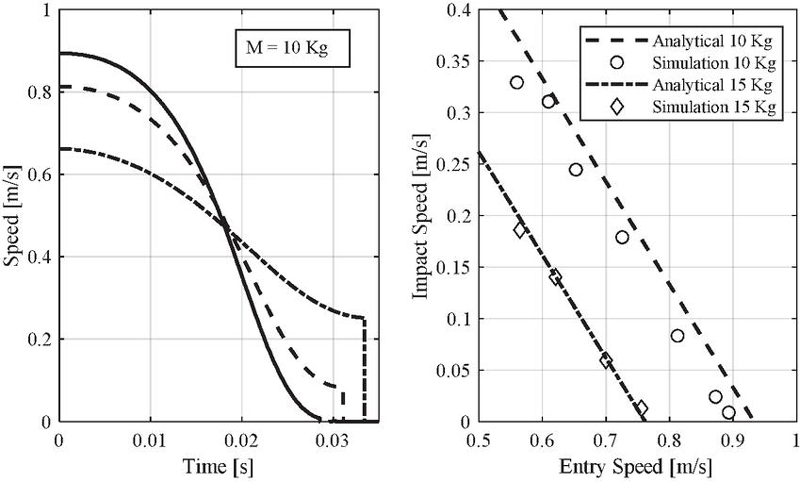
Figure 4 Comparison of analytical estimations with non-linear simulation results.
3 Novel Desing Method
The proposed design method is based upon selecting a cylinder that operates at its maximum loading capacity (given by the end-cushion) for the intended motion task. Using the analytical expression for impact speed, the maximal admissible entry speed in the end-cushion can be calculated with Equation (15). Additionally, to relate the limit of the loading capacity of the end-cushion to the actual motion task, the maximal admissible entry speed in the end-cushion is assumed to be the average speed of the cylinder movement. This assumption neglects the acceleration phase of the cylinder at the start of the movement. It should be noted that represents the moving time of the cylinder and does not include the delay time before the movement starts.
| (15) |
From the rearranged equation in Equation (16) becomes evident, that maximal kinetic energy on the left side, which can be absorbed via the end-cushion is proportional to the damping volume and the pressure, when the end-cushion is reached. Hence, the loading capacity of the end-cushion is proportional to the installed power of the actuation system, since there exists a correlation between cylinder size and damping volume size.
| (16) |
The specific geometric dimensions which depend on cylinder size and design, are then placed on the left side of the equation. The resulting metric for the novel sizing method is the damping volume of the end-cushion. This value should be provided by the manufacturers of pneumatic cylinders to assess the moving time and choose the optimal cylinder size. To date some manufacturers provide the length of the end-cushion [29] and some manufacturers provide the damping value in their datasheets [30]. In the appendix, a table can be found, which summarizes the damping volume found in cylinders of different manufacturers.
| (17) |
3.1 Downstream Resistance and Delay Time
Based on the maximal steady state cylinder speed, given by Equation (15), the necessary sonic conductance can be calculated using the following formula proposed by Reinertz [31]. The formula considers the exhaust air flow being choked flow and isothermal. The value of the sonic conductance can be used to choose a throttle check valve accordantly.
| (18) |
The novel approach only approximates the transfer time. To calculate the total time needed to accomplish the motion task, the delay time before the cylinder starts moving also needs to be considered. The total delay time is a result of the time for pressure adaptation before the cylinder movement and the inherent valve switching time , with the latter usually provided in the datasheet.
| (19) |
Reinertz provides an expression for the time delay due to pressure adaptation [31], which for pure motion tasks is only valid in the retraction stroke (Equation (3.1)), due to the definition used for the operating pressure. Nevertheless, the accuracy of this expression will be investigated in Section 4.
| (20) |
3.2 Summary of Final Formulas for the Design Method
The final proposed algebraic equations for cylinder sizing result from integrating Equations (13) and (14) into Equation (17) respectively. For the given motion task and the desired total transfer time, the optimal size of the damping volume can be found and thereby the optimal size of the pneumatic cylinder. All that is needed is to calculate the required damping volume for the given motion task using Equations (21)–(22) and choose a cylinder using the diagram in the appendix.
Extension:
| (21) |
Retraction:
| (22) |
Once the cylinder size is determined the necessary downstream resistances can be calculated using Equations (23) and (24). It should be noted that this is the total downstream resistance of the entire return path, which includes the tubes, throttle check valve and main switching valve. Formulas for the static downstream resistance of pneumatic tubes can be found in ISO 6358-3 as well as additional rules for multiple components connected in series. This way the sizing of the downstream paths can be achieved.
3.3 Comparison with the Eigenfrequency Dimensioning Method
The eigenfrequency dimensioning method proposed by Doll is widely used and was validated using a comprehensive simulative study. Since this method can be considered as the state of the art, the key differences and similarities of both methods will be highlighted in this section.
Doll provides the following formula to determine the cylinder size, whereby represents the dead volume of the pneumatic drive system including the tubing expressed as cylinder length [11]. Furthermore, is a dimensionless sizing number referred to as “pneumatic frequency ratio”, which relates the dynamics of the motion task to the actor dynamics. It should be noted that in the eigenfrequency method the total time, does not include the time delay of the valve,
Extension:
| (23) |
Retraction:
| (24) |
| (25) |
To allow for a comparison between the novel and Doll’s approach, the same parameters and the assumption of immediate valve switching need to be used with the novel scheme. Hence, for comparison, the time delays of the valve in Equations (21) and (22) are neglected and the resulting damping volumes are described by means of their lengths , piston areas , and area ratios of the end-cushion to the piston . This leads to the simplified Equations (26) and (27) of the novel approach for extension and retraction:
| (26) | ||
| (27) |
There exists a similar structure between the formulas of the novel and Doll’s approach, which is quite surprising considering that they were derived from completely different ideas. Doll arrived at his sizing formula by considering similarity transformations, a useful tool of dimensional analysis. While the novel proposed approach follows an approximation of the maximal loading capacity of the end-cushion, thus considering the end-cushion as the limiting factor for pneumatic sizing. The key differences can be summarized as follows:
• While Doll considers a rodless cylinder, the novel approach makes a differentiation between extension and retraction on how the operating pressure is considered, due to the cylinder area ratio and its impact on the delay time. However, in the extended form of the eigenfrequency method, the cylinder area ratio could be included by means of an external force [16].
• The novel approach neglects the impact of dead volumes on the estimation of the moving time, provided that the tubing is properly dimensioned to allow the proper functioning of downstream throttling (downstream throttle should be the dominating resistance on the exhaust process).
• There is an additional term in the new formula that relates the cylinder length to the geometry of the end-cushion. As Doll correctly pointed out, the length of the end-cushion does not scale with the cylinder length. This observation was used to explain the higher values for longer cylinders in his original paper, since the similarity transformations do not account for this different scaling [11].
Figure 5 shows the total transfer time over the cylinder length for two different dead volumes resulting from using both methods. Due to the operating pressure being differently calculated for retraction or extension, higher achievable transfer times for retraction can be observed. The diagram illustrates the key challenge, when using the frequency method, being that only a range of values is suggested (for a well dimensioned cylinder, lays between 1.1 and 1.7 [11]). This results in a high uncertainty when guessing the exact value of , which is only exacerbated by the dependency of on the cylinder length.
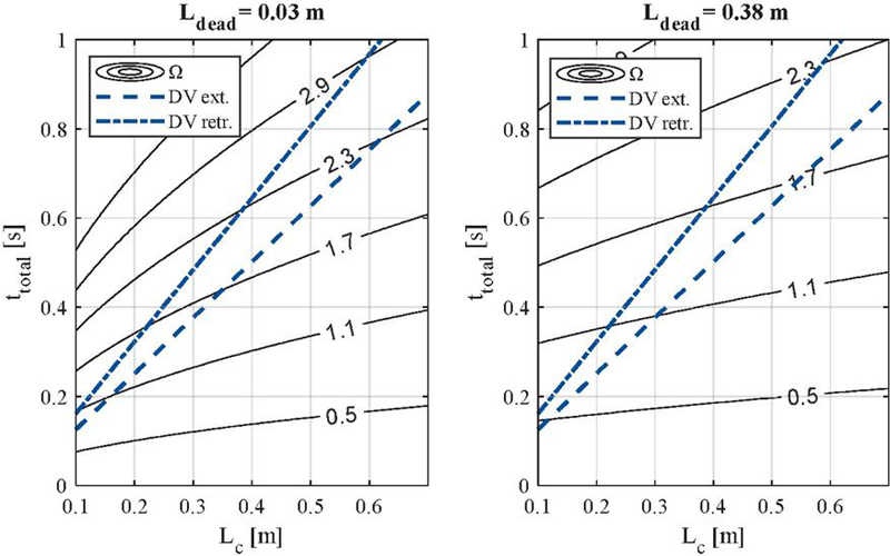
Figure 5 Comparison of damping volume sizing method (DV) with the eigenfrequency method using different -values: Cylinder size ø 32 mm, moving mass 10 kg.
By equating the coefficients, the following expressions for can be found. For a given actuation system (consisting of cylinder, pneumatic lines and valve), the omega value should remain constant, independent of changes in pressure, moving mass, or total transfer time. The interactions of these parameters are the same for both design methods. Equations (28) and (29) will be later used in Section 4 to assess the accuracy of the novel design method by comparing the expected omega values to the measured ones.
| (28) | ||
| (29) |
3.4 Further Considerations Regarding External Loads
It is close at hand, that with a simple change in the definition of the operating pressure, the consideration of external forces in the design process can be achieved. For loads acting against the movement, the resulting equations for the operating pressures are defined as follows:
| (30) | ||
| (31) |
With higher forces acting against the movement the operating pressure entering the end-cushion is reduced. Which reduces the load capacity of the end-cushion. The resulting design formula does not have a closed form, but it can be easily solved iteratively with very low computing effort.
| (32) | ||
| (33) |
Provided that the design formula retains its accuracy, this would increase the applicability of the design method. A thorough validation under different external force conditions is beyond the scope of this paper and should be regarded as future work. The relevance of the gap between existing design guidelines for pure force and pure motion application is highlighted by the efforts to extend the eigenfrequency method to external forces recently proposed by Doll [16].
4 Validation
The validation of the novel design method and proposed equations was conducted experimentally. A total of 16 cases were investigated, comprising combinations of different cylinder sizes, lengths, moving masses, and tube lengths, as summarized in Table 1. The tested cylinders were provided by two different manufacturers, and the supply pressure was constant for all cases at 7 bar. The table also includes the measured transfer times and delay times. The end-cushion was adjusted following the definition of optimal adjustment () presented in Section 2.1. Furthermore, in all cases, the cylinder speed was increased as far as possible, ensuring that the end-cushion operated at its maximum loading capacity to reach zero impact acceleration and near zero impact speed. None of the tests revealed any limitation regarding downstream resistance. The test rig used for this work has been presented in previous work [32, 33] and will therefore not be discussed in this paper.
Table 1 Summary of the investigated load cases
| Tube | Tube | |||||||
| cyl. Ø | Length | Size | ||||||
| [mm] | [mm] | [kg] | [m] | [mm] | [ms] | [ms] | [ms] | [ms] |
| 25 | 250 | 5 | 1 | 6 | 258 | 288 | 45 | 80 |
| 5 | 4 | 6 | 292 | 343 | 69 | 90 | ||
| 5 | 6 | 6 | 295 | 354 | 88 | 111 | ||
| 10 | 1 | 6 | 345 | 403 | 40 | 93 | ||
| 32 | 200 | 10 | 1 | 6 | 265 | 278 | 47 | 73 |
| 10 | 4 | 8 | 262 | 298 | 82 | 100 | ||
| 10 | 6 | 8 | 270 | 309 | 105 | 125 | ||
| 15 | 1 | 6 | 305 | 337 | 42 | 84 | ||
| 320 | 10 | 1 | 6 | 401 | 473 | 53 | 96 | |
| 10 | 4 | 8 | 370 | 449 | 87 | 123 | ||
| 10 | 6 | 8 | 375 | 442 | 107 | 138 | ||
| 15 | 1 | 6 | 493 | 550 | 47 | 113 | ||
| 40 | 200 | 10 | 1 | 8 | 210 | 240 | 35 | 58 |
| 20 | 1 | 8 | 259 | 289 | 39 | 64 | ||
| 500 | 15 | 1 | 8 | 560 | 667 | 53 | 133 | |
| 20 | 1 | 8 | 660 | 738 | 53 | 150 |
In Figure 7 a summary of different speed curves for the extension stroke of measured cases are presented. It can clearly be seen that impact speed near zero without a rebound for all shown cases is achieved.
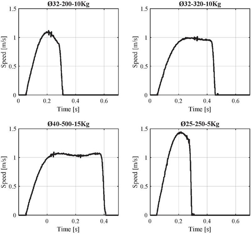
Figure 6 Measured speed curves in the extension stroke for different load cases.
The authors would like to note that a shorter cylinder with a diameter of 25 mm and a length of 150 mm was also tested. However, the results of this test are not included in this paper because optimal adjustment of the end-cushion, as defined previously, could not be achieved. Despite fully opening the damping-throttle, the cylinder still exhibited overdamped behavior, indicating insufficient sonic conductance of the damping-throttle. A worsening of damping performance beyond a certain cylinder length limit is mentioned in [19], but no further information on the cause is provided. Since the main mechanism behind this phenomenon was not investigated in this paper, the authors refrain from stating a fixed lower limit for cylinder length below which the presented design method is no longer applicable. Nonetheless, the sizing of very short cylinders should be separately investigated in future work.
To visualize the accuracy of the novel design method, the experimentally measured values for the moving time are compared to the analytically calculated values. A polytropic exponent of 1 was used for all cases. Figure 6 shows the experimental results in remarkable agreement with the analytically calculated values across all cases. In fact, all experimental cases lie within an absolute error for the estimated transfer time of 40 ms, which corresponds to a maximal relative error of 12%. The method also correctly predicts longer moving times in the retraction stroke. The high accuracy of the method may result from errors in the linear model (as shown in Figure 4) being partially counteracted by the assumption made in Equation (15). However, this statement was not thoroughly proven.
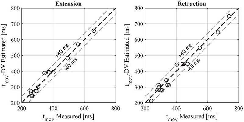
Figure 7 Experimental results for the moving time and analytical estimations using the damping volume method.
Figure 7 depicts the estimated and measured total delay time. On the extension stroke, only the valve delay is utilized for estimation, as Equation (3.1) is not valid. Conversely, for the retraction stroke, the total delay time comprises the valve delay and pressure adaptation delay.
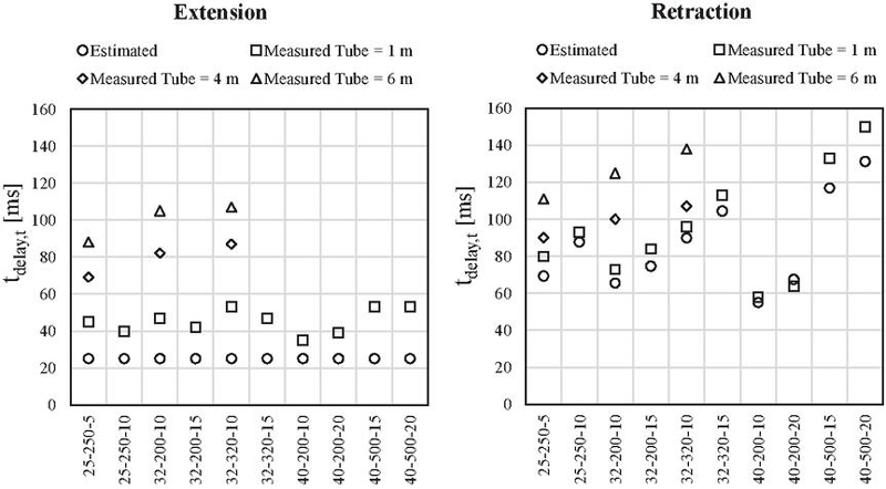
Figure 8 Comparison of analytical estimations of the delay time with experimental results.
It is noticeable that on the extension stroke, pressure build-up impacts the total delay time, leading to underestimation of the measured delay time for all cases, with the measured delay time increasing with longer tubes. For the retraction stroke, the estimated delay time matches well the measurements for short pneumatic tubes. However, for longer tubes, the delay time increases, while Equation (22) (based on Equation (3.1)) do not account for tube length in the calculation. In summary, the proposed formula for time delay provides a good approximation for short tube lengths but underestimates the time delay for longer tubes due to transient effects of long pneumatic lines in pressure build-up and depressurization. Thus, more accurate modelling of the lines is needed to correctly approximate the time delay in motion tasks.
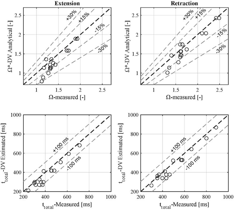
Figure 9 Experimental results for the total transfer time and analytical estimations using the damping volume method.
Finally, the estimated total transfer time and omega values can be evaluated against the measured ones in Figure 9. Due to the delay time being underestimated specially for longer tubes, the maximal estimation error of the total transfer time is increased to 100 ms, which result in a maximal relative error of 28%. The diagram also illustrates that Doll’s statement of a well-dimensioned cylinder having omega values between 1.1 and 1.7 is mostly valid, as most investigated cases lie within this range. However, the longest cylinder exhibit omega values of 1.9 for extension and up to 2.5 for retraction.
5 Summary and Conclusions
This paper shows a novel method for sizing downstream throttled pneumatic cylinders for motion tasks. The method is derived from the maximal loading capacity of the end-cushion and has as sizing metric the damping volume in the end-cushion. The sizing approach is experimentally validated for different load cases and shows great accuracy regarding the estimated transfer time of the cylinder. The main conclusions from the sizing method and experimental study can be summarized as follows:
• Optimal sizing of a pneumatic cylinder is achieved at the minimal achievable cycle time and surprisingly corresponds to the minimal mechanical impact wear on the cylinder ().
• The minimal achievable cycle time is determined by the loading capacity of the end-cushion, which is dependent on the moving mass, the operating pressure and the size of the damping volume.
• The relative sizing relationships for a defined pneumatic actuation system correspond to those outlined in Doll’s eigenfrequency method.
• The motion time of the cylinder is only very weakly depended on tube length or dead volumes of the actuation system, provided that the tubing is properly dimensioned to allow the proper functioning of downstream throttling (downstream throttle should be the dominating resistance on the exhaust process).
• On the other hand, the delay time is greatly increased with tube length.
Furthermore, there are some challenges that need to be addressed in future work:
• The presented formula to estimate the delay time drastically underestimates the delay time for long pneumatic lines, due to them not being considered by the used assumptions. Therefore, a better approximation of the time delay is needed, which considers the transient effects of long pneumatic lines.
• During the experimental investigation of a short cylinder a highly overdamped behaviour was observed. Thus, the sizing of very short pneumatic cylinders needs to be investigated in detail.
• The integration of external forces in the sizing method should be experimentally investigated since this would greatly increase the applicability of the method.
Acknowledgement
The research and development project S-LEAP – Quick-Exhaust for increasing the performance and efficiency of exhaust throttled pneumatic drives – was funded by the European Union and the state of North Rhine-Westphalia. The authors would like to express their sincere thanks to all project partners, the European Regional Development Fund and the state of NRW.
Annex
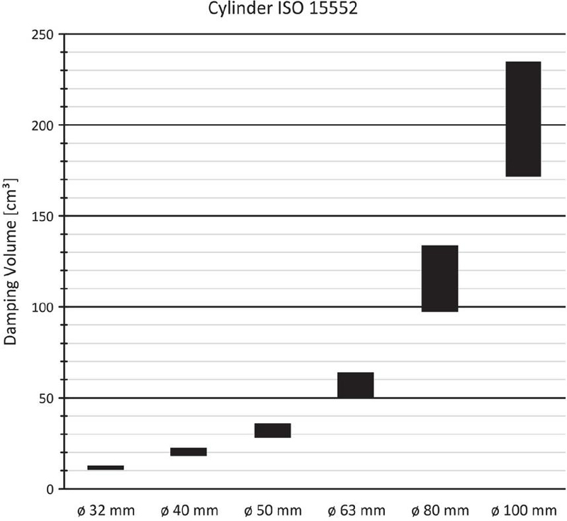
Figure 10 Damping volumes of ISO 15552 series cylinders from different manufacturers.
Derivation of the Simplified Second Order Model of the End-cushion
Starting differential equations:
| (34) | ||
| (35) |
Mass flow under chocked-flow assumption:
| (36) |
By substituting (36) in (35), (35) can be expresses as:
| (37) |
Linearization with Taylor around the nominal steady state point ():
| (38) | |
| (39) |
However, at steady state applies that:
| (40) |
It can be assumed that
| (41) |
By substituting (41) in (39) the final linearized differential equations are:
| (42) | |
| (43) |
Applying Laplace transformation:
| (44) | |
| (45) |
Combining both equations:
| (46) |
The resulting transfer function describes the dynamic response of the cylinder speed to changes in downstream conductivity and has the form of second order linear system:
| (47) |
References
[1] Bimba Corporation, ‘Pneumatic Application and Reference Handbook’, Monee, USA, 2014.
[2] Festo Corporation, “Pneumatic Sizing”, accessed December 5, 2023, https://www.festo.com/eap/en-us\_us/PneumaticSizing/.
[3] Emerson Corporation, “Numasing”, accessed December 5, 2023, https://www.asco.com/en-us/Pages/calculators-numasizing.aspx.
[4] A. Raisch, O. Sawodny, ‘Analysis and optimal sizing of pneumatic drive systems for handling tasks’, Mechatronics, 59: 168–177, 2019.
[5] P. Harris, S. Nolan, G. E. O’Donnell, ‘Energy optimisation of pneumatic actuator systems in manufacturing’. Journal of Cleaner Production, 72:35–45, 2014.
[6] D. Müller, et al., ‘Energy Efficient Pneumatics: Aspects of Control and Systems Theory’, International Journal of Fluid Power, 23(3): 299–342, 2022.
[7] V. Vigolo, V.J. De Negri, ‘Sizing Optimization of Pneumatic Actuation Systems Through Operating Point Analysis’, Journal of Dynamic Systems, Measurement and Control, 143(5): 051006, 2021.
[8] V. Vigolo, V. Boyko, J. Weber, V.J. De Negri, ‘Online Monitoring of Pneumatic Actuation Systems for Energy Efficiency and Dynamic Performance’, Symposium on Fluid Power and Motion Control (FPMC), Sarasota, USA, October 16–18, 2023.
[9] E. Rakova, J. Weber, ‘Exonomy Analysis for the Selection of the most Cost-Effective Pneumatic Drive Solution’, Proceedings of the 9th FPNI Ph.D Symposium on Fluid Power, Florianópolis, Brazil, October 26–28, 2016.
[10] V. Boyko, S. Hülsmann, J. Weber, ‘Comparative Analysis of Actuator Dimensioning Methods in Pneumatics’, Symposium on Fluid Power and Motion Control (FPMC), Virtual, Online, October 19–21, 2021.
[11] M. Doll, R. Neumann, O. Sawodny, ‘Dimensioning of pneumatic cylinders for motion tasks’, International Journal of Fluid Power, 16(1): 11–24, 2015.
[12] M. Doll, ‘Optimierungsbasierte Strategien zur Steigerung der Energieeffizienz pneumatischer Antriebe’, Dissertation University of Stuttgart, 2016.
[13] F. Nazarov, J. Weber, ‘Sensitivity Analysis and Robust Optimization of an Integrated Pneumatic End-Position Cushioning’, 13th International Fluid Power Conference (IFK), Aachen, Germany, pp. 974–988, June 13–15, 2022.
[14] V. Boyko, J. Weber, ‘Energy Efficiency of Pneumatic Actuating Systems with Pressure-Based Air Supply Cut-Off’, Actuators, 13(1): 44, 2024.
[15] O. Reinertz, C. Reese, K. Schmitz, ‘Downstream Throttled Pneumatic Drives with Time-Controlled Pneumatic-Mechanical Quick-Exhaust Valve’, GFPS Phd Symposium, Hudiksvall, Schweden, June 17–20, 2024.
[16] M. Doll, R. Neumann, W. Gauchel, ‘Sizing of Pneumatic Drives under Energy Efficiency Aspects’, Proceedings of the 14th International Fluid Power Conference (IFK), Dresden, Germany, March 19–25, 2024.
[17] M. Guelker, ‘White Paper – Innovative air cushion solution improves productivity and machine reliability and saves money’, Festo Corporation, 2011.
[18] Emerson Corporation (Aventics), Video: “Adjustable cushioning - Advantages”, accessed März 01, 2024, https://www.youtube.com/watch?v=dp\_X6EaR4fw.
[19] P. O’Neil, ‘All About Cylinder Cushioning’, Power and Motion, 2006.
[20] Emerson Corporation, ‘Catalog Aventics Series CAT - Measuring instrument for adjusting the pneumatic cushioning’, 2020.
[21] O. Ohligschläger, ‘Pneumatische Zylinderantriebe – thermodynamische Grundladen und digitale Simulation’, Dissertation, RWTH Aachen, 1990.
[22] F. Nazarov, J. Weber, ‘Heat Transfer Model of Pneumatic End-Position Cylinder Cushioning’, International Journal of Fluid Power, 23(1), 1–18, 2021.
[23] F. Nazarov, J. Weber, ‘Modelling, Simulation and Validation of the Pneumatic End-Position Cylinder Cushioning’, Proceedings of the 17th Scandinavian International Conference on Fluid Power SICFP, Linköping, Sweden, June 1–2, 2021.
[24] P. Beater, ‘Pneumatic drives: System Design, Modelling and Control’, Springer Verlag, Berlin, 2007.
[25] A. Raisch, O. Sawodny, ‘Modeling and Analysis of Pneumatic Cushioning Systems Under Energy-Saving Measures’, IEEE Transactions on Automation Science and Engineering, 17(3): 1388–1398, 2020.
[26] K. Ogata, ‘Modern Control Engineering – Third Edition’, Prentice-Hall, University of Minnesota, 1997.
[27] J. Falcao Carneiro, F. Gomes de Almeida, ‘Reduced-order thermodynamic models for servo-pneumatic actuator chambers’, Proceedings of the Institution of Mechanical Engineers Part I Journal of Systems and Control Engineering, 220(4): 301–314, 2006.
[28] M. Göttert, ‘Bahnregelung servopneumatischer Antriebe’, Dissertation, Universität Siegen, 2004.
[29] Festo Corporation, ‘Catalog: Standards-based cylinders DSBC, ISO 15552’, 2023.
[30] IMI Norgren Corporation, ‘Catalog ISOLine: Standards-based cylinders ISO 15552’, 2024.
[31] O. Reinertz, K. Schmitz, ‘Optimized Pneumatic Drives through Combined Downstream and Adaptive Upstream Throttling’, Symposium on Fluid Power and Motion Control (FPMC), Bath, United Kingdom, September 9–11, 2020.
[32] C. Reese, O. Reinertz, K. Schmitz, ‘A Comprehensive Study of Energy-Saving Strategies through Combined Throttling’, International Journal of Fluid Power, 25(1), 1–26, 2024.
[33] C. Reese, O. Reinertz, K. Schmitz, ‘Feasibility Study and Experimental Validation of a Novel Combined Throttling Approach’, 14th International Fluid Power Conference (IFK), Dresden, Germany, March 19–21, 2024.
Biographies

Christian Reese Jimenez received the bachelor’s degree in mechanical engineering in 2017 and the master’s degree in general mechanical engineering from RWTH Aachen University in 2019. Since 2019, he is working as a Research Associate at the Institute for Fluid Power Drives and Systems (ifas), RWTH Aachen University. His research areas include simulation and optimization of fluid power systems and components focusing on enhancing energy efficiency and performance.

Olivier Reinertz received his diploma and his doctoral degree in mechanical engineering from RWTH Aachen University, Germany. He is currently Scientific Director at the Institute for Fluid Power Drives and Systems (ifas) at RWTH Aachen University. His research focuses on the model-based analysis of fluid power components and systems and the derivation and validation of innovative strategies for efficiency and performance optimization with an emphasis on compressed air and gas-powered systems.

Katharina Schmitz received a graduate’s degree in mechanical engineering from RWTH Aachen University in 2010 and an engineering doctorate from RWTH Aachen University in 2015. She is currently the director of the Institute for Fluid Power Drives and Systems (ifas), RWTH Aachen University.
International Journal of Fluid Power, Vol. 26_3, 381–410.
doi: 10.13052/ijfp1439-9776.2632
© 2025 River Publishers