Assessment of Fuel Saving Potential in a Hybridized Off-Road Vehicle: A Study Combining Virtual Simulation and Experimental Validation
Weijin Qiu1,*, Shubham Ashta1, Gregory M. Shaver1, Scott C. Johnson2 and Bryan C. Frushour3
1Ray W. Herrick Laboratories, Purdue University, West Lafayette, Indiana, USA
2John Deere Intelligent Solutions Group, John Deere, Fargo, North Dakota, USA
3John Deere Electric Powertrain, John Deere, Waterloo, Iowa, USA
E-mail: qiuweijin@alumni.purdue.edu
*Corresponding Author
Received 26 November 2024; Accepted 27 February 2025
Stricter emissions regulations have imposed significant pressure on off-road OEM companies to decrease fuel consumption in their products. This situation has led to the adoption of powertrain hybridization as a viable solution, making the timely assessment of fuel-saving potential for hybridized vehicles essential. In this study, a real-time hardware-in-the-loop (HIL) simulation platform was developed to incorporate a vehicle power management strategy for efficient power distribution, component-level controllers for overseeing actuator functions, and physics-based models of powertrain components to accurately replicate vehicle performance. Results from simulations conducted on the HIL platform indicate that the hybridized off-road heavy-duty wheel loader under investigation can achieve fuel savings of over 10%. Furthermore, additional field testing confirmed these findings by comparing the fuel consumption of a prototype vehicle equipped with the hybridized powertrain to that of its baseline counterpart.
Keywords: Off-road vehicle, hybrid electric vehicle, energy management, hardware-in-the-loop simulation.
Hybridizing off-road vehicles through electrification is essential for addressing the significant environmental and operational challenges faced by the agricultural and industrial sectors [1]. Transitioning to electrified powertrains enables off-road heavy-duty vehicles to substantially reduce harmful emissions, thus improving air quality and minimizing environmental impact [2]. In addition, electrification enhances operational efficiency, lowers operating costs, and reduces reliance on fossil fuels, promoting sustainability and resource conservation [3]. This shift towards electrification aligns with evolving regulatory standards and societal expectations regarding carbon emissions and environmental responsibility. Furthermore, electrified powertrains offer enhanced torque characteristics, precise power delivery, and quieter operation, contributing to improved performance and operator comfort [4]. Accordingly, embracing electrification in off-road vehicles is a pivotal step towards creating a cleaner, more sustainable future for industrial and agricultural machinery, ensuring a healthier environment and more efficient operations for years to come.
Researches in this domain have addressed various critical topics, including hybrid powertrain architecture design, component sizing and integration, energy management strategies, and battery management systems. Studies such as those presented by [5, 6, 7, 8] provide extensive reviews of different powertrain architectures, discussing their respective advantages and disadvantages. Furthermore, researches by [9, 10, 11, 12] propose various methodologies for the optimal sizing of electric motors, batteries, and internal combustion engines (ICE) to balance performance, efficiency, and cost effectively. Despite these advancements, challenges persist in developing energy management strategies that synergize with battery management systems to reduce energy consumption while extending battery life. To tackle these obstacles, researches by [13, 14, 15] develop multi-dimensional innovative energy management strategies to enhance efficiency or prolong battery life in hybrid vehicles. Continued research and development in these areas are essential to overcome existing challenges and fully harness the potential of electrification in off-road vehicles.
As one of the largest OEM corporations in the United States, John Deere launched its first production electric wheel loader, the 644K, in 2012. This model marked a transition from a traditional transaxle with a hydraulic torque converter to a series electric powertrain without an energy storage system. This initial evolution reduced the engine size from 9.0 L to 6.8 L and achieved a 30% improvement in fuel efficiency. The current work is part of a research initiative aimed at developing a battery-hybrid wheel loader for John Deere, building on the foundation of the 644K series electric wheel loader by further downsizing the engine, incorporating an electric energy storage system. To validate the feasibility of this design and assess its fuel saving potential, a comprehensive and integrated simulation framework capable of achieving the same is required.
Hardware-in-the-Loop (HIL) simulation is a testing methodology used primarily in the development of complex real-time embedded systems, particularly in automotive and aerospace applications. It involves integrating physical hardware components with simulation models to create a testing environment that closely mirrors real-world conditions. HIL simulation is distinguished from other simulation methods by its real-time characteristics. It enables immediate feedback through real-time processing, ensuring that hardware responses are generated without significant delays, thereby allowing for dynamic behavior representation. HIL simulations utilize high-fidelity models to mirror the actual performance of systems under various conditions, while managing low latency through optimized communication protocols. This approach allows for scalable test scenarios and effective integration with control algorithms, facilitating rapid iteration and optimization. Additionally, HIL provides a safe testing environment, enabling the validation of real-world performance without the risks associated with physical testing [16]. Overall, the real-time nature of HIL simulation enhances the reliability and efficiency of system development and assessment.
Considering the characteristics of HIL simulation, it is ideally suited for validating the feasibility of the newly proposed off-road wheel loader introduced in this study and evaluating its fuel-saving potential.
This study is structured as follows: The second chapter delves into the system modeling and control development of the newly proposed off-road wheel loader, providing a general overview of the design process. In the third chapter, we present the vehicle power management (VPM) algorithm, which is specifically crafted to regulate the power flows between various energy sources and the power-consuming components of the vehicle. The fourth chapter introduces the HIL testing platform, detailing its setup and presenting the results obtained from HIL simulations, which validate the control strategies and system performance, and assesses the fuel saving potential of the proposed vehicle. The fifth chapter showcases field testing results derived from the operation of a demo vehicle featuring newly proposed design against a baseline vehicle, offering insights into its real-world performance and efficiency. Finally, the concluding section summarizes the key findings of the study and outlines potential avenues for future work.
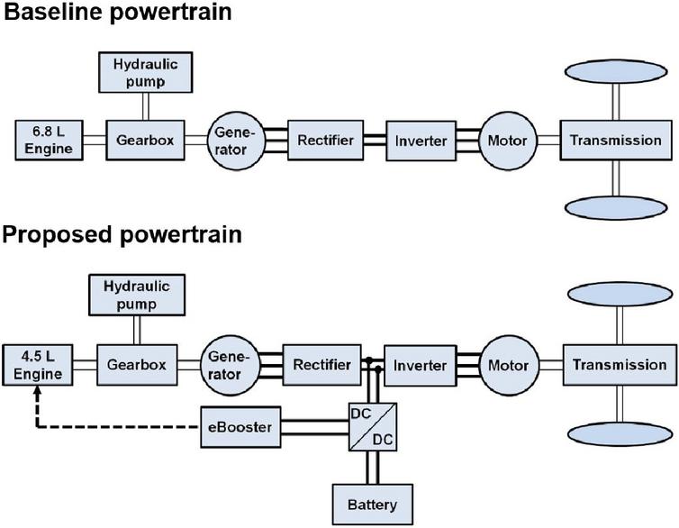
The top plot of Figure 1 illustrates the configuration of the baseline wheel loader analyzed in this research. It features a 6.8 L diesel engine connected to a generator motor and a hydraulic pump for bucket operations, all through a planetary gearbox. The generator motor produces AC power, which is converted to DC power by a rectifier. For clarity, the DC-link between the rectifier and inverter is not shown. When the generator motor supplies electricity, the inverter can draw direct current from the DC-link and convert it back into alternating current to power the electric motor for vehicle propulsion.
Figure 1 Powertrain architectures.
The powertrain of the proposed wheel loader depicted in the bottom plot of Figure 1 undergoes a transformation from the baseline configuration by reducing the engine size from 6.8 L to 4.5 L and integrating a battery pack to compensate for the diminished torque and power capability resulting from the engine reduction. Additionally, an electrically-driven pressure charging device, known as an “eBooster”, is introduced to enhance boost pressure and transient engine performance [17].
The 4.5 L turbocharged diesel engine, utilized as one of the two primary power sources for the proposed wheel loader, is illustrated in Figure 2. To model the engine’s performance and fuel consumption, a control-oriented nonlinear mathematical engine model can be developed based on fundamental principles [18]. It is important to acknowledge that, for the sake of simplicity in the model, the dynamics of the eBooster were omitted, although the engine’s torque and power properties have accounted for the influence of the eBooster.
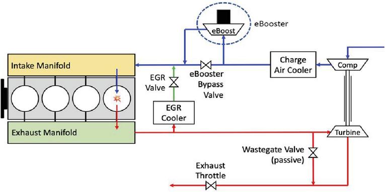
Figure 2 Engine schematic.
Determining the actual engine speed involves conducting a torque balance analysis on the crankshaft of the engine under investigation [19], resulting in:
| (1) |
In the equation above, represents the moment of inertia of the engine crankshaft. , , and denote the indicated torque, the load torque exerted by the hydraulic system, and the load torque applied by the generator motor, respectively. The indicated torque is an output from a production engine speed controller developed by John Deere, which operates in a proportional-integral (PI) control format.
Furthermore, fuel consumption of the 4.5 L engine can be calculated per [20], as expressed below:
| (2) |
In the above expression, stands for gas lower heating value of diesel fuel, which is treated as a constant. denotes brake thermal efficiency and can be modeled as a function of actual engine speed and air-fuel ratio (AFR) [21]. Note that AFR value is interpolated from a manufacturer-provided calibration map based off actual engine speed and indicated torque. Figure 3 demonstrates an illustrative diagram of the engine model and control strategy deployed in this study.
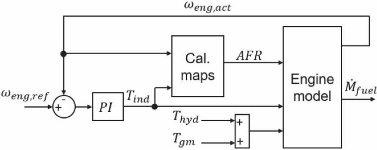
Figure 3 Engine model & control diagram.
The battery model employed in this study is relatively straightforward, aiming primarily to forecast the state-of-charge (SOC) of the battery at any given moment and the system voltage of the battery. This study utilizes the Coulomb counting method to compute the battery SOC, which necessitates the input of battery current and initial battery SOC to proceed. Here, represents the battery capacity, and denotes the battery current.
| (3) |
The system voltage of the battery can be acquired by referencing a specification data sheet supplied by the battery manufacturer, which establishes a correlation between battery SOC and system voltage. Additionally, the specification data sheet from the battery manufacturer includes current restrictions for charging and discharging based on battery SOC, represented as and , respectively. Figure 4 depicts an illustrative diagram for the battery model.
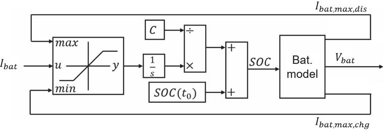
Figure 4 Battery model diagram.
Table 1 presents essential specifications of the acquired battery pack utilized to establish the battery model. It is worth noting that the maximum discharge C-rate of the battery is 5 C, equating to a maximum discharge power of 177.5 kW. The battery is not designed for operation at this power level for more than 10 seconds; hence, this maximum discharge C-rate is labelled as “pulse”. Conversely, the maximum continuous discharge C-rate of the battery is 3 C, corresponding to a discharge power of 106.5 kW. Temperature represents another crucial factor influencing battery properties. For the purposes of this study, it is assumed that the battery and thermal management systems can maintain the battery temperature at approximately 300 K.
Table 1 Specifications of sourced battery
| Specification | Value |
| Nominal voltage | 355 V |
| Min/Max voltage | 288 V/403 V |
| Rated capacity | 100 Ah |
| Rated energy | 35.5 kWh |
| Max discharge C-rate (pulse) | 5 C |
| Max discharge C-rate (continuous) | 3 C |
| Max charge C-rate | 2 C |
The power electronics components examined in this study encompass a generator motor and its associated controlling rectifier, a traction motor and its corresponding controlling inverter, and a DC/DC converter for battery management. To replicate their behaviors during operation within the vehicle under investigation, an electrical circuit for this power electronics system is formulated using the eHS solver, which is a real-time power electronics simulation solver that facilitates simulation of an electric circuit on a FPGA, without needing to write mathematical equations. Figure 5 displays a visual representation of the created electrical circuit.
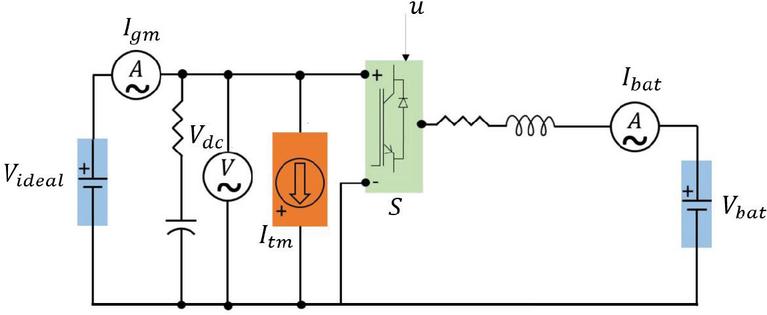
Figure 5 Illustrative layout of designed electrical circuit.
Within the circuit, an ideal voltage source is utilized to simulate the generator and its corresponding bidirectional rectifier, as the rectifier is configured to operate in voltage control mode for the proposed hybrid vehicle design. During the operation of the proposed hybrid vehicle, any activity involving the traction motor or the battery, whether it entails power consumption or power supply, leads to fluctuations in the DC-link voltage, reflecting a power imbalance. By configuring the rectifier in voltage control mode, the generator is prompted to provide or absorb an appropriate amount of electrical power to or from the DC-link, thereby compensating for the power imbalance. The ideal voltage source is adjusted to supply a constant 700 V voltage. Typically, the generator supplies electrical power to the DC-link, resulting in the imposition of an electromagnetic load torque on the engine, denoted by the term in Equation 1. To model this electromagnetic load torque, the current supplied by the generator and the DC-link voltage are measured with a current sensor and a voltage sensor, as denoted in the circuit with the same naming. This load torque can then be formulated as demonstrated in Equation 4, where represents the generator motor efficiency, and signifies the gear ratio between the engine and the generator, and is utilized for further simulation purposes.
| (4) |
To model the traction motor and its associated bidirectional inverter, an ideal current source labelled as is utilized within the circuit. This approach is adopted to simulate two specific scenarios: vehicle propulsion, during which the traction motor draws current from the DC-link, and vehicle braking, where the traction motor injects current into the DC-link. The magnitude of the current passing through this ideal current source is contingent upon the power required by the operator for propulsion or braking , and the efficiency of the traction motor , as outlined below.
| (5) |
The accuracy of the DC/DC converter model for battery control in this study, denoted as in the circuit, surpasses that of the other power electronics models, as it is intended to validate an actual controller governing battery current in simulation. Figure 6 presents a more intricate layout of the converter model.
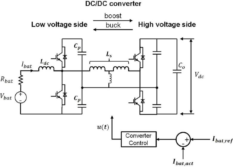
Figure 6 Illustrative layout of converter model.
The proposed hybrid vehicle necessitates a high-power bidirectional DC/DC converter to interface with the vehicle’s battery, given the substantial voltage differential between the 700 V DC-link (high voltage side, HVS) and the battery, which has a nominal voltage of 350 V (low voltage side, LVS). When power transfers from the battery to the DC-link, the DC/DC converter operates as a boost converter. Conversely, when the power flow direction is reversed, the DC/DC converter functions as a buck converter. The magnitude and direction of power flow between the battery and DC-link are regulated by a converter controller, which operates as a PI controller in current control mode. The input to the converter controller constitutes the error between the reference battery current and the actual battery current, compelling the converter controller to respond and generate appropriate gating signals to achieve an instantaneous desired phase angle shift between LVS and HVS voltages. This is accomplished by a specific gating pattern, assuming a constant drive profile and switching frequency. Ultimately, this phase angle shift , as depicted in the equation below, aligns the actual battery current with the reference battery current, where denotes the converter’s switching frequency.
| (6) |
To verify the DC/DC converter’s ability to effectively regulate battery current, a current sensor measuring battery current is integrated into the circuit. Additionally, another ideal voltage source measuring battery voltage is introduced to simulate the battery voltage and complete the circuit, with the voltage value being derived from the previously described battery model.
For certain component-level controllers to operate effectively, a supervisory-level vehicle power management (VPM) strategy must provide the necessary reference signals. At the system level, this VPM strategy governs the regulation of power flows within the vehicle by generating directives for the component-level controllers to execute [22]. The control architecture of the proposed hybrid vehicle is depicted in Figure 7. Notably, the control variables derived from the power management strategy chosen for this hybrid vehicle consist of the commanded engine speed for the engine controller, the commanded battery current for the converter controller, and the available torque limit for the inverter controller.
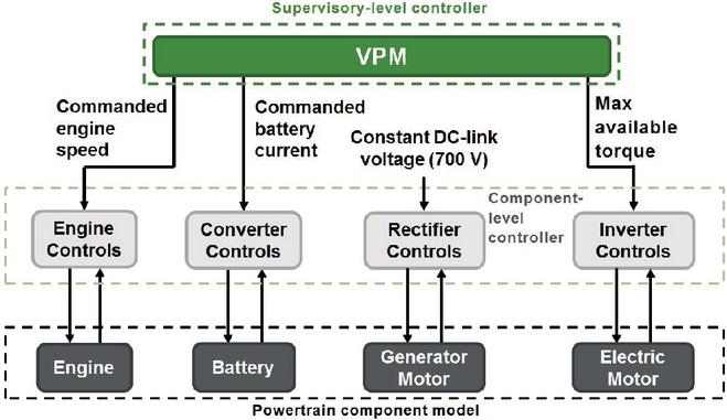
Figure 7 Control architecture of the proposed hybrid vehicle.
Fundamentally, the developed VPM strategy for this research should have the ability to distribute the power demanded by the operator from multiple power sources to various power consuming units of the proposed vehicle (within physical constraints), optimize engine operation for maximum efficiency, and manage battery operation to maintain battery state of charge (SOC). Figure 8 illustrates the heuristic-based algorithm of the designed VPM strategy for calculating the commanded engine power and the commanded battery current . In the algorithm, , , and , represent the hydraulic power requested by the operator, the traction power requested by the operator, and the auxiliary load power estimated by the vehicle’s transmission control unit (TCU), respectively. It is noteworthy that these requested power terms are predominantly positive, although may be negative during energy regeneration. Additionally, , , , and are defined as follows:
| (7) |
In the above equation, is defined as a tunable control limit of the battery in the format of a PI controller, with the differential value between target SOC and actual SOC being the controller input, and battery power control limit being the controller output.
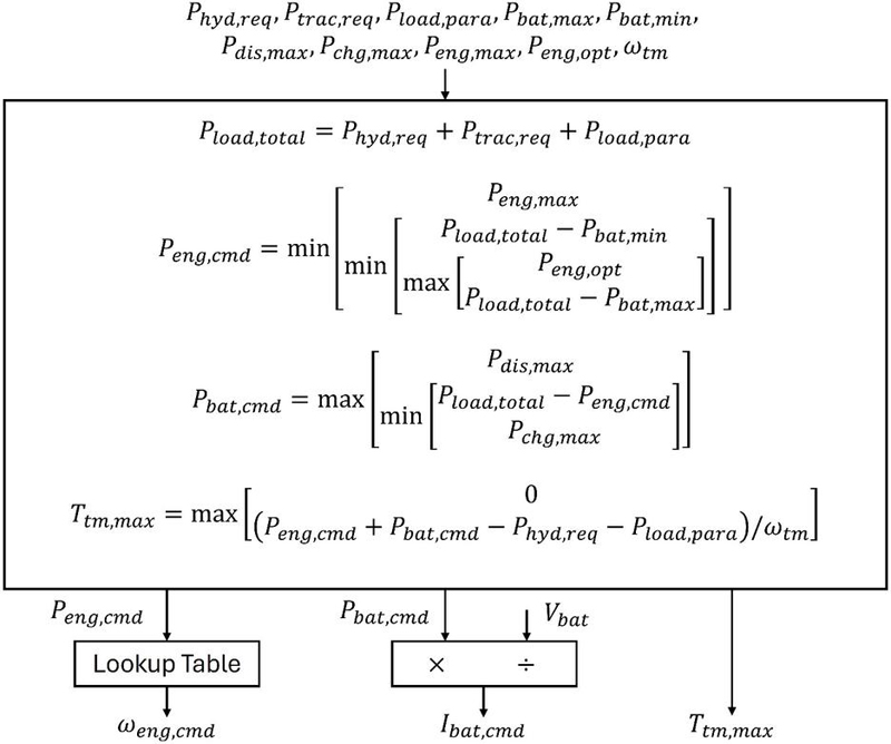
Figure 8 Vehicle power management strategy.
Additional terms requiring clarification in the algorithm include the maximum engine power at the current engine speed, the optimal engine power indicating the power level at which the engine achieves the lowest brake specific fuel consumption (BSFC) value, and the traction motor speed .
After determining the commanded engine power , the VPM strategy will choose a commanded engine speed based on the engine efficiency map. This selected engine speed aims to achieve the best fuel economy while operating at the specified power level. Nevertheless, the chosen engine speed may be constrained by various factors, such as the operational speed limit of the hydraulic pump, leading to a suboptimal engine speed as the ultimate result.
Through the generation of commanded engine power and commanded battery current , the VPM strategy can compute the available power limit for the electric motor with the aid of the TCU. This calculated value is then transformed into a maximum torque value that the electric motor can deliver for vehicle propulsion, serving as the third output. Further detailed explanation about this algorithm can be found in [23].
In this research, a novel HIL simulation platform has been established, and Figure 9 displays an actual image of the deployed HIL simulator. This simulator comprises four main components: a physical control board (which refers to the “in-the-loop” hardware of this system), is housing the designed VPM strategy and a converter controller for the battery (which serves as the control algorithm/software to be validated in this study); an FPGA module utilized for executing the eHS solver to simulate the power electronics employed in this study; a CPU module responsible for simulating the plant model; and a host PC used as a console and monitor.
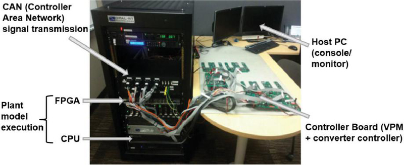
Figure 9 Image of the real HIL test rig.
To provide a clearer depiction of its structure and the interactions between each element, Figure 10 illustrates a layout of the platform.
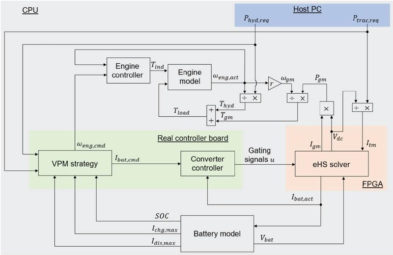
Figure 10 Configuration of HIL simulator setup.
For the HIL simulation, two typical production drive profiles of the baseline wheel loader, noted as “Hopper” and “Transport”, are replicated in the HIL simulation platform for the proposed wheel loader. Figure 11 depicts the concept of replicating a real production drive profile performed by a baseline vehicle on the HIL simulation platform for the proposed vehicle. Note that the requested hydraulic power and traction power in simulation are modeled to match exactly the hydraulic power and traction power of the baseline vehicle during field tests. In other words, the proposed vehicle is required to generate the same amount of hydraulic power and traction power in HIL simulation as those produced by the baseline vehicle in real-life conditions.
The first drive profile noted as “Hopper” features a classic “V-pattern” mode of operation where a wheel loader moves toward a pile of materials to scoop them into its bucket, reverses and approaches a loading truck, unloads the materials, and then returns to its initial position to repeat the process. This drive profile is also illustrated in Figure 11.
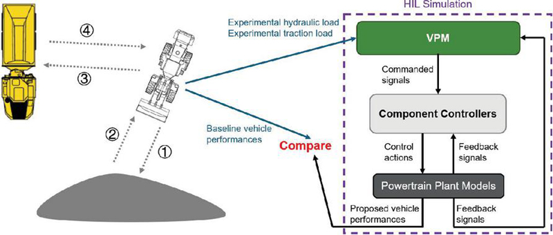
Figure 11 Illustration of reproducing a “Hopper” drive profile.
The second drive profile referred to as “Transport” involves a straight-line acceleration test in which the wheel loader accelerates to its maximum speed and maintains that speed until the next acceleration event. The illustration of this drive profile is omitted due to its simple profile pattern.
Figure 12 and Figure 13 present the comparison between the experimental results of the baseline wheel loader and the simulated results of the proposed wheel loader under the “Hopper” drive profile. Note that all the legends marked as “Battery vehicle” equivalently refer to the proposed vehicle.
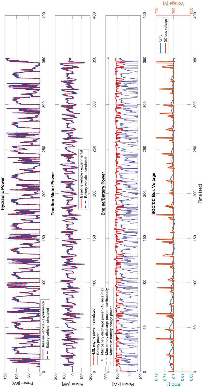
Figure 12 HIL simulation result – Hopper – Plot # 1.
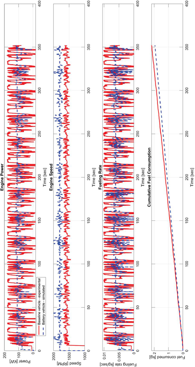
Figure 13 HIL simulation result – Hopper – Plot # 2.
This is a drive profile where both the hydraulic pump and electric motor are employed heavily, as reflected in the first two plots of Figure 12, which illustrate the power consumption of the hydraulic pump and the electric motor throughout the run respectively. The red solid line denotes the baseline wheel loader from the experimental data, while the blue dashed line represents the proposed wheel loader as simulated. Remarkably, the two lines overlap almost perfectly, revealing negligible differences between the vehicles in these key performance metrics. This observation underscores that, despite its downsized engine, the proposed wheel loader can achieve performance on par with that of the baseline wheel loader, thanks to the effective support of the battery.
The third plot in Figure 12 analyzes the engine and battery performance of the proposed vehicle during simulation. The results indicate that the downsized engine operates at a highly efficient power level throughout the entire run, while the battery primarily engages during more demanding operations. A positive battery power value indicates discharging, whereas a negative value signifies charging. The upper black solid line represents the maximum discharge power limit for pulse operation, while the lower black dashed line indicates the maximum discharge power limit for continuous operation. According to the user manual, the battery power should not exceed these limits for more than 10 seconds. The red line denotes the maximum charging power limit for the battery. Overall, this plot demonstrates that the battery, managed by the supervisory-level VPM controller, is being charged and discharged effectively within its normal physical limits.
The last plot in Figure 12 reviews battery SOC and DC-link voltage for this run. It can be observed that the battery SOC at the end of the drive profile (70%) is recovered back to its initial value thanks to the regulation by the supervisory-level VPM controller, indicating the sustainability of the proposed vehicle to work on this drive profile continuously. Furthermore, the DC-link voltage has been well maintained at around 700 V, suggesting that there is no power shortage nor power excess within the powertrain of the proposed vehicle. Thus it can be concluded that the supervisory-level VPM controller is functioning properly in simulation in terms of delivering requested vehicle performances, operating the engine efficiently, regulating battery SOC, and achieving power balance within the vehicle.
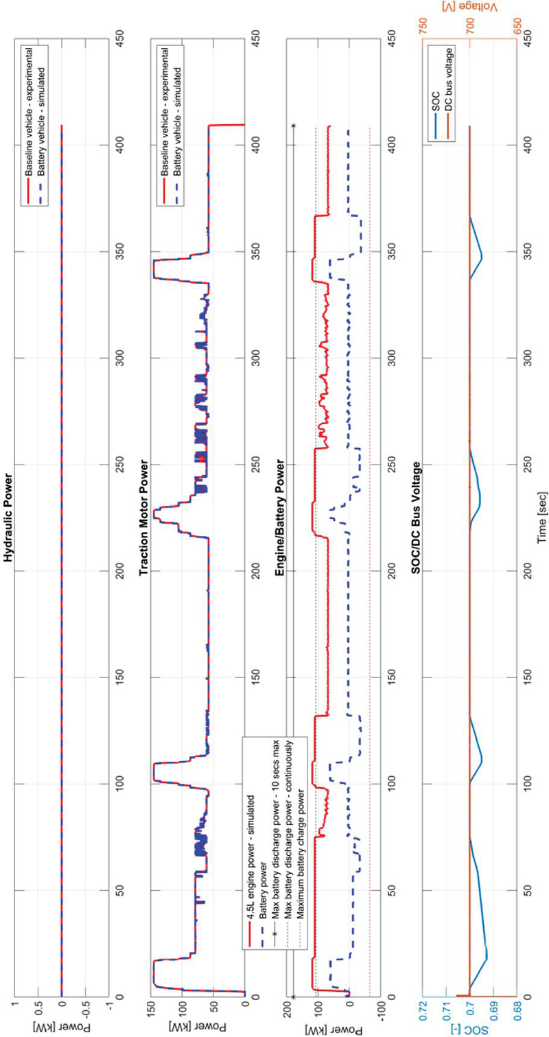
Figure 14 HIL simulation result – Transport – Plot # 1.
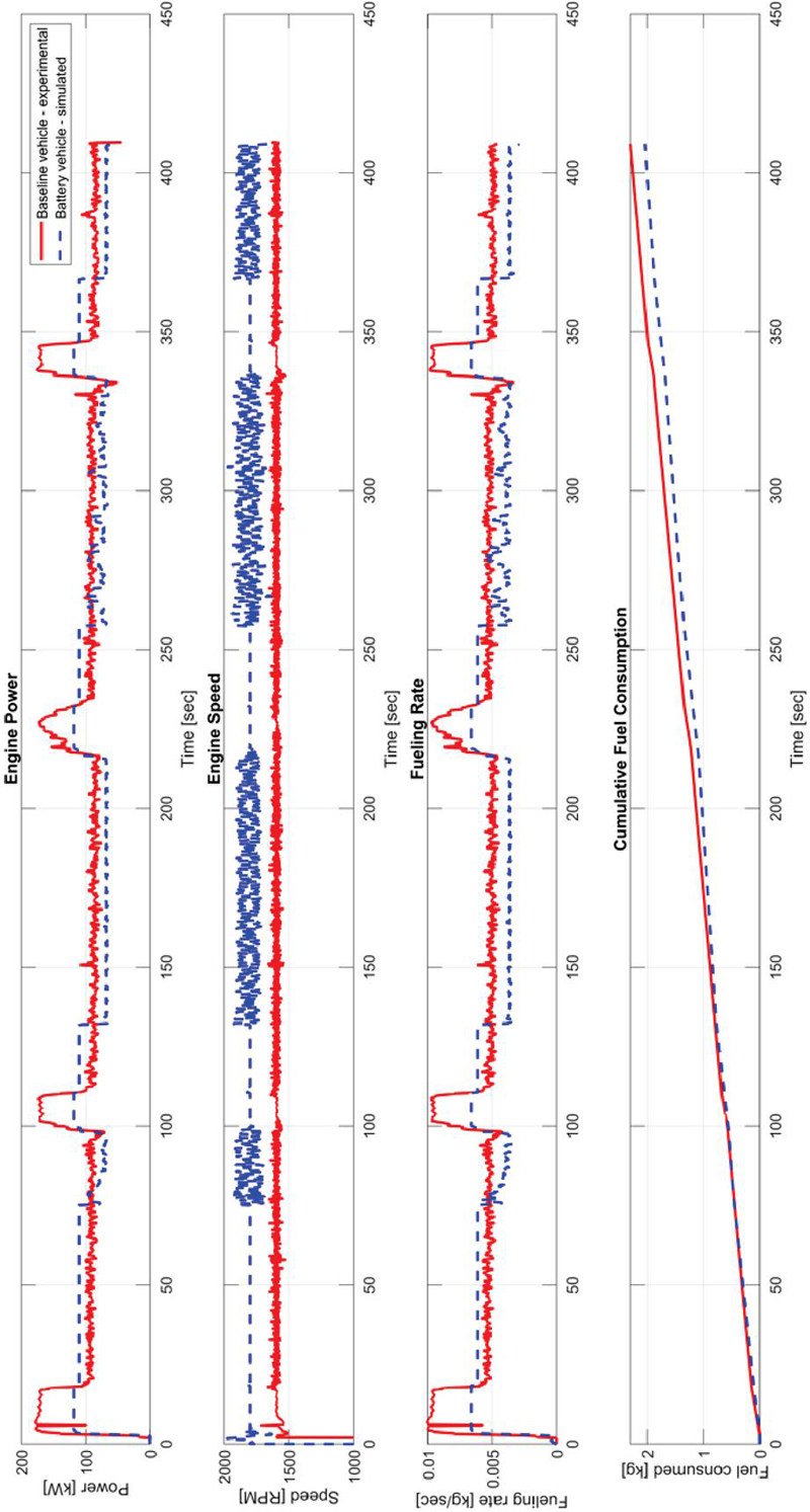
Figure 15 HIL simulation result – Transport – Plot # 2.
Figure 13 specifically compares engine performances of the two vehicles. The first plot displays the engine power for both vehicles, clearly indicating that engine power peak shaving has been achieved for the proposed vehicle, as evidenced by a significant reduction in power variation, attributable to the battery’s support. Engine power peak shaving allows the downsized engine to remain in its efficient operating range for extended periods, which is highly advantageous for fuel savings.
The second plot in Figure 13 illustrates the engine speeds of both vehicles. It is evident that the engine speeds for both vehicles are predominantly held at a constant level. Because there is no mechanical power transfer from the engine to the traction transaxle, the engine speed becomes decoupled from the vehicle speed. This results in reduced engine speed variation, making the vehicle easier to operate and minimizing noise production.
The third and fourth plots in Figure 13 present the fueling rate and cumulative engine fuel consumption for both engines throughout the drive profile. The engine fueling rate is calculated using experimental and simulated engine speed and torque, based on brake specific fuel consumption (BSFC) static maps provided by Deere. The cumulative engine fuel consumption represents the integration of the fueling rate over time. According to these calculations, the baseline vehicle consumes 2.18 kg of fuel by the end of the drive profile, whereas the proposed vehicle uses only 1.95 kg, resulting in a fuel savings of 10.5% with the proposed vehicle.
Figure 14 and Figure 15 compare the simulated results of the battery wheel loader with the experimental results of the baseline wheel loader, both under the “Transport” drive profile. The key takeaways from the HIL simulation results with respect to the “Transport” drive profile are not significantly different from those of the “Hopper” drive profile. The only notable distinction lies in fuel consumption. According to the last subplot of Figure 13, the baseline vehicle consumes 2.29 kg of fuel by the end of the drive profile, while the proposed vehicle uses only 2.04 kg, leading to a fuel savings of 11.0% for the proposed vehicle.
To further validate the fuel-saving potential assessed through the SIL and HIL simulation, John Deere constructed a real demonstration vehicle equipped with the proposed battery hybrid powertrain for conducting in-field experimental validation.
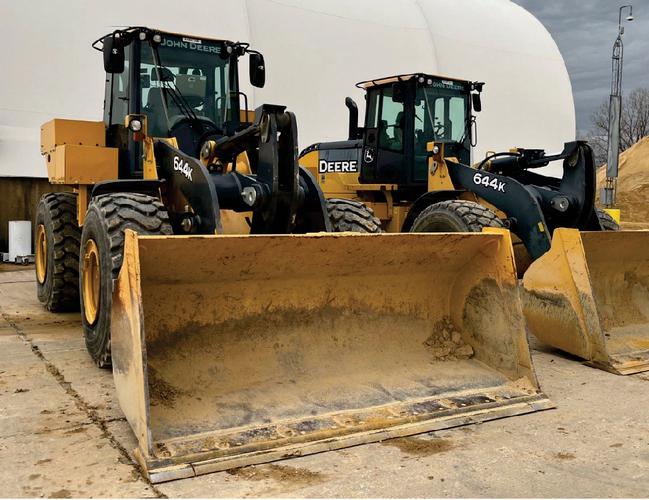
Figure 16 Actual view of tested vehicles – left: proposed vehicle; right: baseline vehicle.
After completing the necessary controller programming, setting up CAN bus communication, and conducting thorough interface validation and functional checks, the proposed battery hybrid wheel loader (equipped with a 4.5 L engine) was fully operational. It is important to note that the same controller board and communication bus protocols used for the VPM and converter controller code were implemented on the actual demonstration vehicle. Additionally, a series electric baseline loader (featuring a 6.8 L engine) was deployed for back-to-back testing, allowing for direct comparative results between the two vehicles. Figure 16 illustrates the two wheel loaders deployed for in-field testing.
The first in-field experimental validation was carried out following the “Hopper” drive profile as illustrated in Figure 11, with the exception that for the “Hopper” drive profile, the truck was substituted with a hopper-conveyor machine. This change enabled the measurement of the weight of materials being moved during each run. Utilizing the hopper-conveyor allows the research team to calculate fuel consumption and fuel efficiency based on the weight of materials, providing a more relevant metric from the perspective of a construction machine. Additionally, fuel gauges were deployed to measure the fuel level in the fuel can before and after the “Hopper” drive profile, allowing for accurate assessment of fuel consumption for further analysis.
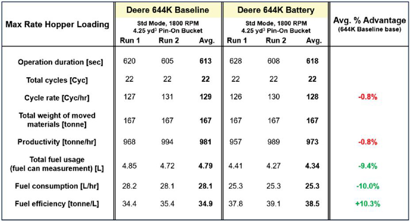
Figure 17 Tabulated in-field experimental results – Hopper.
With the setup described above, a comprehensive summary based on the measurements from the in-field experimental testing has been tabulated by Deere engineers as shown in Figure 17 for “Hopper” drive profile. The same driver operated both wheel loaders respectively to complete the same drive profile, which was performed twice for each loader. The first five rows of the table indicate that the driver operated both vehicles in a nearly identical fashion, resulting in negligible variation between the two vehicles in terms of cycle rate [Cyc/hr] and productivity [tonne/hr], suggesting that the proposed vehicle is capable of matching the performances of the baseline vehicle which aligns with the conclusion drawn from HIL simulation. Apart from that, the total fuel usage result suggests a 9.4% fuel saving, but considering normalization by taking into account fuel consumption (in the format of L/hr) and fuel efficiency (in the format of tonne/L), it can be stated that the proposed vehicle has demonstrated over 10% fuel saving advantage compared to the baseline vehicle. Notably, it has been confirmed that battery SOC at the end of the operation was recovered back to its initial state, hence all the fuel-related numbers in the table are final and justified.
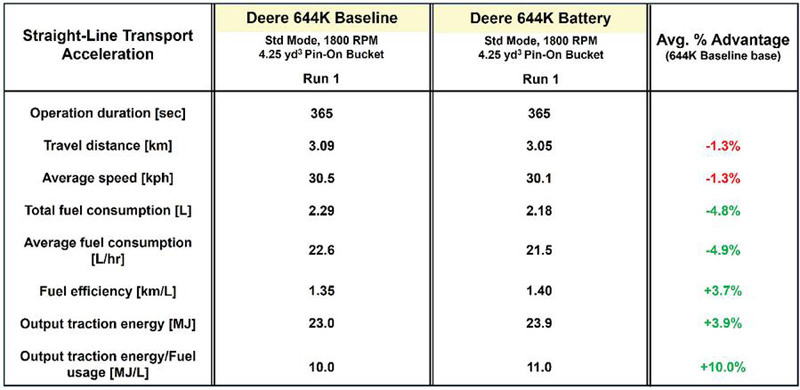
Figure 18 Tabulated in-field experimental results – Transport.
Similarly, detailed statistical analyses for the “Transport” drive profile are tabulated in Figure 18. Note that this drive profile exclusively utilizes traction motor. It can be concluded that the proposed vehicle shows improvements in total fuel usage, average fuel consumption, and fuel efficiency for the “Transport” drive profile. However, these improvements do not match the simulated fuel savings potential of approximately 10%. This discrepancy arises from variations in the output traction energy of the two vehicles. Notably, the proposed vehicle’s output traction energy is 3.9% higher than that of the baseline vehicle, potentially due to differences in tire conditions, vehicle aerodynamics, etc. Considering this factor, fuel consumption can be normalized by dividing the output traction energy by total fuel usage, which reflects the productivity of the vehicles during this drive profile in MJ/L. According to the normalization results, the proposed vehicle is expected to consume 10% less fuel while delivering the same vehicle performance as the baseline vehicle, assuming no variations in uncontrolled factors between the two vehicles.
The growing demand for hybrid powertrains in the off-road vehicle industry over the past decade has been driven by concerns about global warming, rising fuel prices, and stricter government regulations. This increased demand highlights the need for advanced testing methodologies to aid in the design of next-generation hybrid wheel loaders and evaluate their fuel-saving potential. In this research, a state-of-the-art hardware-in-the-loop (HIL) simulation platform has been developed for a battery-hybrid wheel loader currently under investigation at John Deere. This HIL simulator features a supervisory-level vehicle power management (VPM) strategy, component-level controllers, and vehicle powertrain plant models, allowing for the safe and efficient real-time validation of an actual controller board that integrates the VPM strategy and a DC/DC converter controller. It also facilitates the assessment of potential fuel savings of the battery-hybrid wheel loader compared to its baseline counterpart.
The HIL simulation results indicate that the VPM strategy effectively delivers the power required by operators to power-consuming units, ensures efficient engine operation, and maintains a balanced battery state of charge (SOC). Additionally, the DC/DC converter controller’s ability to promptly and accurately regulate battery current to the target value has been confirmed. Due to engine downsizing and powertrain hybridization, the proposed battery-hybrid electric wheel loader is expected to achieve fuel savings of over 10% compared to the baseline wheel loader, a potential that is further validated through in-field experimental testing.
In future endeavors, the authors aim to explore another exciting technology for engine fuel saving purpose, which is the development of a robust coordinated control over gas exchange process involving the eBooster. In recent years there have been successful application with robust coordinated control [24], and discovering how much fuel saving can be realized on the basis of this work when the robust coordinated controller is actually implemented on the demo vehicle would be an appealing research problem to tackle.
[1] W. Qiu, S. Ashta, G. M. Shaver, S. Johnson, and B. C. Frushour, “Facilitating the development of a novel heavy-duty offroad vehicle exploiting hardware-in-the-loop technique,” in 2024 International Maha Fluid Power Conference, River Publishers, 2024.
[2] X. Sun, F. Xin, and K. Gao, “Energy efficiency research of propulsion system for series-parallel hybridization of amphibious vehicles,” Heliyon, vol. 10, no. 15, 2024.
[3] S. Qu, F. Zappaterra, A. Vacca, and E. Busquets, “An electrified boom actuation system with energy regeneration capability driven by a novel electro-hydraulic unit,” Energy Conversion and Management, vol. 293, p. 117443, 2023.
[4] S. Qu, D. Fassbender, A. Vacca, and E. Busquets, “A high-efficient solution for electro-hydraulic actuators with energy regeneration capability,” Energy, vol. 216, p. 119291, 2021.
[5] K. V. Singh, H. O. Bansal, and D. Singh, “A comprehensive review on hybrid electric vehicles: architectures and components,” Journal of Modern Transportation, vol. 27, no. 2, pp. 77–107, 2019.
[6] W. Zhuang, S. Li, X. Zhang, D. Kum, Z. Song, G. Yin, and F. Ju, “A survey of powertrain configuration studies on hybrid electric vehicles,” Applied Energy, vol. 262, p. 114553, 2020.
[7] M. Sabri, K. A. Danapalasingam, and M. F. Rahmat, “A review on hybrid electric vehicles architecture and energy management strategies,” Renewable and Sustainable Energy Reviews, vol. 53, pp. 1433–1442, 2016.
[8] M. A. Masrur, “Hybrid and electric vehicle (hev/ev) technologies for off-road applications,” Proceedings of the IEEE, vol. 109, no. 6, pp. 1077–1093, 2020.
[9] S. Kokjohn, J. Mazenec, D. Rothamer, J. Ghandhi, N. Vang, G. Shaver, W. Qiu, S. Ashta, and B. Frushour, “Improving efficiency of off-road vehicles by novel integration of electric machines and advanced combustion engines,” tech. rep., Univ. of Wisconsin, Madison, WI (United States), 10 2024.
[10] Y. Huang, H. Wang, A. Khajepour, B. Li, J. Ji, K. Zhao, and C. Hu, “A review of power management strategies and component sizing methods for hybrid vehicles,” Renewable and Sustainable Energy Reviews, vol. 96, pp. 132–144, 2018.
[11] M. Li, L. Wang, Y. Wang, and Z. Chen, “Sizing optimization and energy management strategy for hybrid energy storage system using multiobjective optimization and random forests,” IEEE Transactions on Power Electronics, vol. 36, no. 10, pp. 11421–11430, 2021.
[12] T. Zhu, R. G. Wills, R. Lot, X. Kong, and X. Yan, “Optimal sizing and sensitivity analysis of a battery-supercapacitor energy storage system for electric vehicles,” Energy, vol. 221, p. 119851, 2021.
[13] H. Zhang, F. Wang, J. Wu, B. Xu, and M. Geimer, “A cycle-adaptive control strategy to minimize electricity and battery aging costs of electric-hydraulic hybrid wheel loaders,” Energy, p. 134655, 2025.
[14] I. Shafikhani et al., “Energy management of hybrid electric vehicles with battery aging considerations: Wheel loader case study,” Control Engineering Practice, vol. 110, p. 104759, 2021.
[15] Q. Zhang, F. Wang, B. Xu, and Z. Sun, “Online optimization of pontryagin’s minimum principle for a series hydraulic hybrid wheel loader,” Proceedings of the Institution of Mechanical Engineers, Part D: Journal of Automobile Engineering, vol. 236, no. 7, pp. 1487–1499, 2022.
[16] W. Qiu, S. Ashta, G. M. Shaver, S. C. Johnson, B. C. Frushour, and K. Rudolph, “Expediting hybrid electric wheel loader prototyping: Real-time dynamic modeling and power management through advanced hardware-in-the-loop simulation,” IEEE Transactions on Vehicular Technology, 2024.
[17] S. Ashta, N. Vang, W. Qiu, C. Emegoakor, S. H. Rayasam, T. Swedes, J. Mazanec, G. Luis, B. Frushour, G. Shaver, et al., “Empowering off-road diesel powertrains: Advanced multivariate air handling control for electrified performance,” in 2024 International Maha Fluid Power Conference, River Publishers, 2024.
[18] S. Harsha Rayasam, W. Qiu, T. Rimstidt, G. M. Shaver, D. G. Van Alstine, and M. Graziano, “Control-oriented modeling, validation, and interaction analysis of turbocharged lean-burn natural gas variable speed engine,” International Journal of Engine Research, vol. 24, no. 2, pp. 738–754, 2023.
[19] W. Qiu, S. H. Rayasam, G. M. Shaver, T. Rimstidt, D. G. Van Alstine, and M. Graziano, “Modeling and robust coordinated control of turbocharged natural gas engine with genset application,” IFAC-PapersOnLine, vol. 55, no. 24, pp. 39–44, 2022.
[20] W. Qiu, S. H. Rayasam, G. M. Shaver, T. G. Rimstidt, and D. G. Van Alstine, “Control design-oriented modeling and -synthesis-based robust multivariate control of a turbocharged natural gas genset engine,” International Journal of Engine Research, vol. 24, no. 9, pp. 3905–3921, 2023.
[21] S. H. Rayasam, W. Qiu, G. M. Shaver, T. Rimstidt, and D. G. Van Alstine, “Robust switching mimo control of turbocharged lean-burn natural gas engines,” IFAC-PapersOnLine, vol. 55, no. 24, pp. 7–12, 2022.
[22] W. Qiu, An integrated framework for modeling, robust coordinated control, and power management of advanced powertrains featuring turbocharged engines. PhD thesis, Purdue University Graduate School, 2023.
[23] W. Qiu, S. Ashta, G. M. Shaver, J. Mazanec, S. Kokjohn, S. C. Johnson, K. Rudolph, and B. C. Frushour, “System configuration, control development, and in-field validation of a hybrid electric wheel loader featuring electrically-boosted engine,” Control Engineering Practice, vol. 150, p. 105989, 2024.
[24] S. H. Rayasam, W. Qiu, T. Rimstidt, G. M. Shaver, and D. G. Van Alstine, “Robust model-based switching mimo air handling control of turbocharged lean-burn si natural gas variable speed engines,” International Journal of Engine Research, vol. 24, no. 6, pp. 2783–2804, 2023.

Weijin Qiu received the B.S. degree in Agricultural Engineering from China Agricultural University, in 2018, and the Ph.D. degree in Mechanical Engineering from Purdue University, in 2023. He is currently a senior power electronics control engineer with John Deere. His research interests include systems, measurements, and controls, primarily focusing on hybrid vehicles, internal combustion engine, and power electronics.

Shubham Ashta received the B.S. degree in Mechanical Engineering from Indian Institute of Technology, Madras, in 2018, and the Ph.D. degree in Mechanical Engineering from Purdue University, in 2024. He is currently a high-voltage product design engineer with Daimler Truck North America.

Gregory M. Shaver is an American mechanical engineer and an academic. He is the director of Ray W. Herrick Laboratories and a professor at Purdue University. He earned his B.S. in Mechanical Engineering from Purdue University in 2000, followed by an M.S. in Mechanical Engineering from Stanford University in 2004. He later obtained a PhD in Mechanical Engineering from Stanford in 2005. His research interests include thermodynamics, systems, measurements and controls, primarily focusing on combustion, transportation, sustainable energy and human-machine interaction.

Scott C. Johnson received the M.S. and Ph.D. degrees in Electrical Engineering with Purdue University studying observer design for switched systems. He is currently an engineering manager in power electronics with John Deere. He develops new algorithms for precision agriculture, hybrid vehicles, and vehicle power management. He is also a Leader with John Deere in power electronics hardware in the loop simulations. He is passionate about the latest control methods, including reinforcement learning, model predictive control, adaptive control, and more.

Bryan C. Frushour received the B.S. in Electrical Engineering with Indiana University Indianapolis in 2006. He is currently a staff engineer with John Deere focusing on the design of electric powertrains.
International Journal of Fluid Power, Vol. 26_2, 99–128.
doi: 10.13052/ijfp1439-9776.2621
© 2025 River Publishers