Centralized Pressure Control and Displacement Quantization with Digital Displacement Pumps
Jordan Pascale1,*, Chris Williamson1, Jim Hennen2 and Paul Rindahl2
1Danfoss Power Solutions, Iowa, USA
2MTS Systems, Eden Prairie, Minnesota, United States
E-mail: jpascale@danfoss.com; cwilliamson@danfoss.com; jim.hennen@mts.com; paul.rindahl@mts.com
*Corresponding Author
Received 04 December 2024; Accepted 11 March 2025
Danfoss Power Solutions has developed a centralized pressure control solution for multi-pump hydraulic power units (HPU) in the industrial market. This system architecture has been developed around the use of the Digital Displacement Pump (DDP) which is highly efficient over a wide range of operating conditions and has typically shown a 30% decrease in electrical input energy over similar systems using axial piston pumps.
MTS Systems, a leading global supplier of test and simulation systems, expanded this centralized control to work in a harmonized fashion with other pumping technologies housed within unique motor-pump modules; some containing DDP and others containing conventional axial piston pumps. This arrangement provided several benefits and empirically demonstrated the DDP module efficiency over the axial piston pump module in supplying fluid power to dynamic downstream force and motion systems that replicate real-world automotive drive files and test track profiles.
Special consideration was required when implementing DDP in a system with multiple pumps’ (maximum of 6) outlet flow combined in parallel. Allowing each individual pump controller to operate in pressure control mode caused compounding complexity in tuning, and noisy, unstable flow pulsations. As a solution, a centralized pressure control scheme was implemented in which a system level microcontroller evaluated user inputs, pressure signals from a transducer, executed logic, and output displacement commands to each pump controller as required to meet the system demand. What makes this control scheme unique is that in a multi-pump system, one pump has a continuously variable displacement fraction with any value from 0 to 100%. The other pump displacements were controlled in a quantized manner with stepped values of displacement (for example: 0%, 25%, 75%, 100%). Hose resonant frequencies were also avoided in this manner.
Testing and implementation of this control scheme has proven to be effective in reducing system tuning complexity and undesirable flow pulsations in the system. Measured results indicate that the average pressure ripple power was reduced by 28% to 94% and the average pressure ripple band power by 61% to 98% (pump module dependent).
Successful implementation of the centralized control allowed MTS to demonstrate through an energy efficiency study that HPUs equipped with DDP consume up to 37.5% less energy than those with swashplate pumps for a given test cycle.
Keywords: Digital displacement, hydraulic power units, centralized pressure control.
Energy conservation to reduce CO emissions becomes increasingly prominent for industrial equipment. Last year, the EU adopted European Sustainability Reporting Standards, which require publicly traded EU companies to disclose CO emissions in their annual reports, beginning in fiscal year 2024.
The economic benefits of energy efficiency are also compelling, particularly in European countries where the price of electrical power has increased dramatically in recent years. The United States government finds that pumps represent 27% of the electricity used by industrial systems [1]. Energy is the largest cost of ownership of an industrial pump system, representing 50% to 90% of total life cycle costs, depending on the technology.
Digital Displacement Pump (DDP) technology was invented at the University of Edinburgh [2]. The basic DD principle is activating cylinders individually with an electronic controller, varying the pump displacement volume by on/off control rather than by reducing the piston stroke. This method enables high energy efficiency and fast, precise flow control. Innovation in Scotland led to numerous successful demonstrations of digital fluid power for renewable energy, industrial machinery, on-highway and off-highway vehicles, and more. Danfoss Power Solutions acquired Artemis Intelligent Power and its DDP portfolio in 2021. Danfoss brought DDP to market with the DDP096 pump [3], and Danfoss continues to introduce new DD components and systems. Digital pumps and motors also have been a research topic at multiple universities over the last 20 years, and new contributions to the field are published continuously. A full bibliography of the state of the art would be too large for this paper. The interested reader can find extensive references in [4] and a few interesting examples of more recent works in [5] through [8].
Hydraulic Power Units (HPU) are a mainstay of many industrial installations. HPUs convert electrical power to fluid power with one or more hydraulic pumps driven by electric motors. HPUs include associated components such as a reservoir, filters, control valves, accumulators, sensors, controllers, and so on. A typical HPU has AC induction motors driving variable displacement, pressure-compensated piston pumps. Large installations with multiple pumps in parallel may have trouble with pressure control stability if each pump is individually pressure-compensated. Consequently, a multi-pump HPU may synchronize pump commands with a single hydro-mechanical pressure control and a common pilot line connected to all pumps.
If an HPU has periods of low power demand, motors with variable frequency drives (VFD) are an alternative method to improve efficiency by adjusting motor speed to reduce standby power loss. However, VFD efficiency decreases with decreasing motor load [9]. A VFD paired with an axial piston pump has an efficiency curve that initially increases with speed, peeks at mid-range and then declines as the speed continues to rise. Thus, the highest efficiency is not achieved at the lowest or highest speeds, but somewhere in between. The variable speed application uses about 4% more energy than the fixed speed module at its corner power even though the horsepower required is the same which is not what one would expect from a power saving application. VFD harmonic distortions need also be considered.
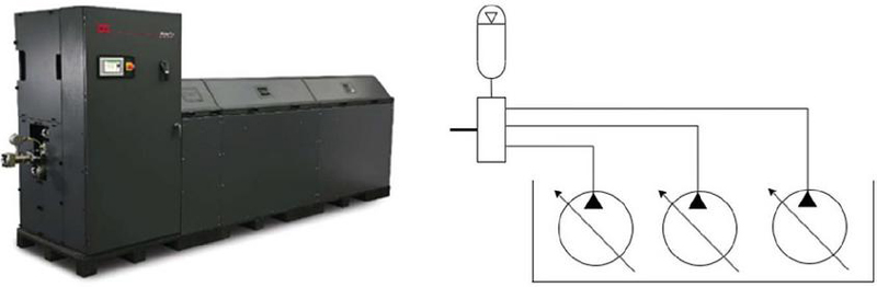
MTS Systems is a leading global supplier of test and simulation systems. This testing relates to applying precision forces and motions to help understand the physical properties of structures, components, materials, and the accuracy of model-based designs. The HPU is the backroom fluid power producer that feeds fluid power through a network of pipes and valves to the front room test operations. The actuator system in the front room imparts forces and motions into the test article, such as a vehicle or structure. MTS SilentFlo HPU are designed to be used with servocontrolled, electro-hydraulic systems. MTS HPU are scalable with multiple pump/motor modules arranged in single, 3-module and 6-module arrays. The pump/motor modules are submerged in the hydraulic reservoir to save space and reduce noise.
Figure 1 MTS SilentFlo HPU.
Total energy efficiency of a test system can be rather low if unmanaged. Efficiencies at each stage of power transmission from electrical to fluid to mechanical actuation domains are multiplied together to realize the efficiency of the physical test system. For example, if each power conversion step is 90% efficient, then the overall efficiency 90% 90% 90% 73%. Efficiencies based on conventional technologies in these three phases of transmission need to consider the full operating range from idling to full power consumption. Total system efficiency in the range of 30% to 60% is typical with conventional unmanaged swash-plate piston pumps in the HPU. Typical losses in an axial piston pump include volumetric losses from leakage, mechanical losses caused by friction in bearings and seals, and churning losses due to fluid agitation within the pump housing. These losses increase with higher pressures and speeds. A managed modular approach to power generation addresses both the electrical to fluid domains. It is most efficient to operate the fewest motor-pump-modules to meet the required flow demand of the system. For this reason, MTS implement the scaled scheduling of 114 LPM (30 GPM) modules in a Run-On-Demand (ROD) approach with the intent of operating with a flow buffer that defaults to operating the minimum number of modules in advance of the flow demand. An example of a 6 swashplate-pump HPU is represented in Figure 2 below. Each pump has a maximum flow rate of 114 liters per minute. Turning off some pumps, when possible based on flow demand, improves energy efficiency. “No scheduling 684” means that all 6 pumps run constantly with a maximum flow rate of 684 LPM. The other legend categories in Figure 2 indicate maximum total flow rates with some modules switched off. The ROD scheme allows pump modules to operate closer to their corner power and away from the idling region of lowest efficiencies. Although the ROD scheme is a significant improvement over no scheduling, power losses are always a summation of all running modules.
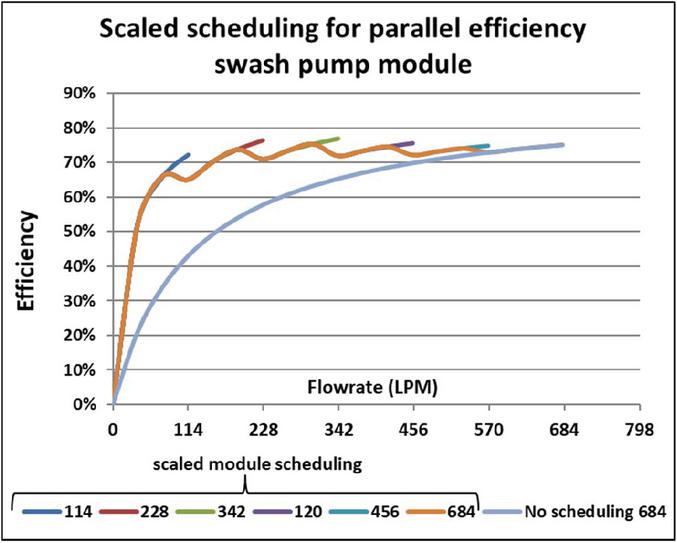
Figure 2 Run-on-demand scheduling of 114 LPM (30 GPM) modules with efficiencies.
With the goal of gaining substantial efficiency improvements, and to differentiate themselves in the market, MTS began investigating the use of Danfoss DDP technology for their newest models of HPU. The industry-leading efficiency and control was a key driver for MTS in pursuing the technology. An MTS HPU utilizing DDP technology could reasonably expect a 3 to 5 year payback time based on lower operating cost but would vary depending on the cost of energy and other factors.
The system must be able to deliver the peak flow, but, from an economic point of view, it is also important to know at what flow rates the system is going to operate most of the time. To find the total cost of operating the HPU, the running cost at each operating condition must be calculated and summated. A duration diagram helps estimate HPU energy costs via a histogram distribution of how many hours during an annual period required a given flow rate.
As the project developed, significant challenges became apparent. Because of its digital flow control principle, DDP produces larger flow and pressure ripple output than conventional piston pumps. Flow pulsations can cause control instability and undesirable noise and vibration. A system architecture combining up to 6 DDP modules in parallel, each operating separately in pressure control mode, amplified the pressure oscillations. Quiet, smooth operation was a major goal of the project and a requirement for bringing DDP to production in MTS HPU.
The present paper describes two sets of experiments with the same DDP HPU. The pressure ripple test (see Section 4.1) compares the first prototype control system with distributed pressure control to a more sophisticated, centralized pressure control system. The energy test (see Section 4.2) compares the energy efficiency of the DDP HPU with centralized pressure control to a traditional HPU with swash-plate type pumps.
As previously mentioned, the hydraulic power units built by MTS presented a unique challenge in combining outlet flow in parallel while coordinating the pressure control of up to 6 DDP units in a single HPU. Initially, a “Distributed Control” (represented in Figure 3 below) was attempted by relying on an embedded pressure transducer at each pump’s outlet in conjunction with its DPC12 pump microcontroller. However, there were difficulties in matching pressure setpoint levels between pumps due to variations in transducer tolerances. DDP pressure ripple and interactions between pumps produced substantial noise and hose vibration.
Through testing and analysis, an alternative solution was established through incorporating a stand-alone Danfoss Plus+1 system controller. A unique software architecture was successfully developed around the system controller and implemented in coordination with the DPC12 (pump controllers). The system controller received user setpoint information from the HPU user interface display (pressure setpoint, and maximum flowrate) along with a pressure transducer measurement taken at a single location at the HPU’s outlet. The software in the system controller then calculated appropriate displacement values for each DDP in the system and sent the necessary commands to the pump controllers, thus establishing a “Centralized Control” (represented in Figure 3 below). Details of the centralized control system software architecture are shown in Figure 4, whereas the physical layout of controller hardware is shown in Figure 5. Please note that HPU outlet pressure is measured by two sensors for redundancy.
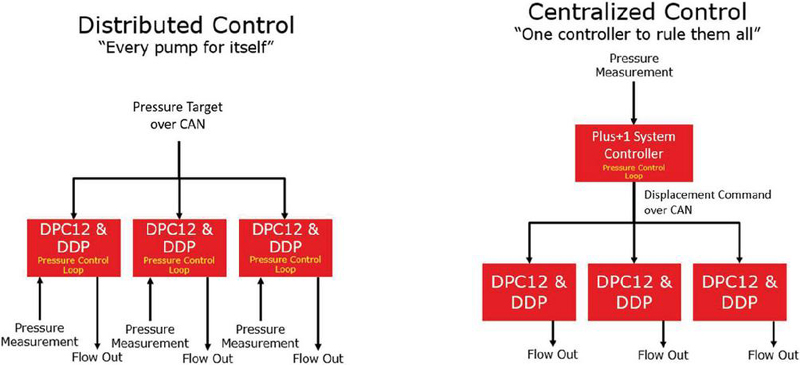
Figure 3 Distributed pressure control vs centralized pressure control.
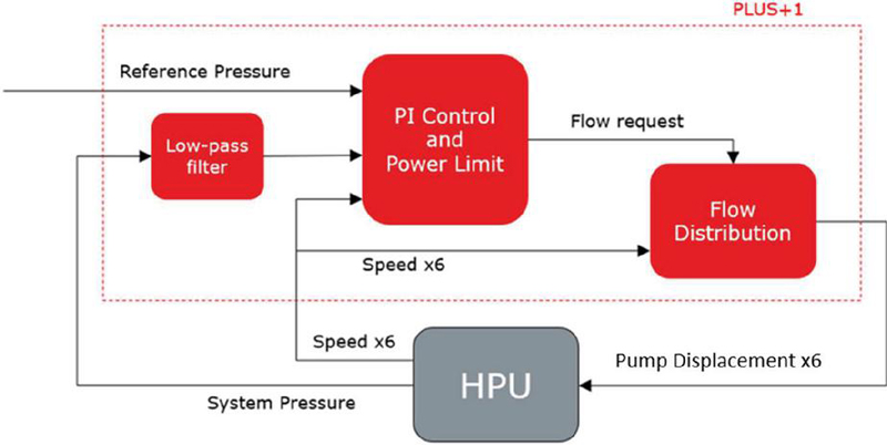
Figure 4 Centralized control software flowchart.
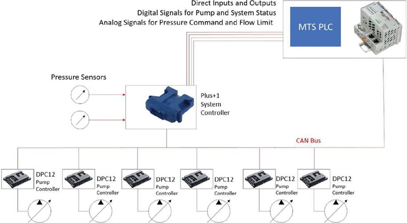
Figure 5 HPU physical control system network diagram with centralized control.
DDP’s flow output inherently produces low-frequency pressure ripple [10]. The pressure ripple frequency spectrum depends on operating condition, specifically the shaft speed and fractional displacement. Pump pressure ripple caused several problems in the distributed multi-pump system. Pump pressure ripple output due to the digital flow algorithm was amplified by the pressure control loop, so-called “self-excitation”. There were undesirable interactions between the pressure control loops with each DPC12 controller responding to pressure changes from other pumps in the circuit. Furthermore, pressure pulsation at certain resonant frequencies caused standing waves in the hydraulic hoses, particularly for the longest hoses in the circuit. Altogether, the distributed control system suffered from significant noise and vibration.
To avoid exciting the hydraulic hoses with pump-induced pressure ripples, Danfoss turned to line resonance theory. By understanding and calculating the fundamental theoretical frequency of the outlet hose at each module using the “open on one end” boundary condition. From test results, the quarter wave, “one end open” boundary condition was selected as the ideal case approximation for the pump outlet hoses on the HPU. The hydraulic circuit downstream of the HPU junction manifold has very low hydraulic stiffness; it includes high-pressure filters, accumulators, and long 2-inch diameter distribution pipes. Pressure waves generated at the pumps reflect back from the junction manifold, almost like a pipe with one end open. The 4x factor in the fundamental frequency equation from Table 1 below gives insight as to how the hose fundamental frequencies were calculated and why the HPU is so sensitive to line length. Table 2 below shows the resulting calculated fundamental frequency values of the module’s hoses.
Table 1 Line resonance with ideal boundary conditions. The “open on one end” case is a good approximation of the DDP outlet hoses on the HPU
| Boundary | Fundamental | Graph | |
| Conditions | Wavelength | Frequency | (Wave Displacement) |
| Open on both ends | |||
| Closed on both ends | |||
| Open on one end | |||
| c speed of sound (m/s) | |||
| L Hose Length (m) |
Table 2 Calculated fundamental frequency of pump modules based on line resonance theory
| Module 1 | Module 3 | Module 4 | Module 6 | |
| Fundamental frequency from theory (Hz) | 54 | 69 | 79 | 112 |
| assume c 1000 (m/s) | ||||
Table 3 Summary of improvements with centralized pressure control
| Problem | Solution |
| Extensive tuning due to part-to-part variation between pressure transducers | Centralized control measures pressure at a single point in the circuit |
| Interaction between pumps increases pressure oscillation | Centralized control has one pressure feedback loop with the measurement point at the junction manifold rather than at a pump outlet port |
| “Self-excitation”: pressure feedback loop amplifies pressure ripple | Low-pass signal filter on measured pressure |
| Pump pressure ripple excites line resonance | Quantization scheme: pumps with longer lines run at constant displacement levels to avoid resonant frequencies. |
With the knowledge of each line’s calculated fundamental frequency, a displacement quantization algorithm was developed and applied to the Centralized Pressure Control that avoids exciting resonant frequencies [11]. Operating pumps at any displacement fraction between 0 and 100% results in a range of fundamental frequencies between 0 and 12 times speed (360 Hz at 1800 rpm). These include enabling frequencies (1) which are pulsations generated by cylinders as they are activated and used. Also present, are disabling frequencies (2) which are generated by the pump as cylinders are deactivated and unused.
The quantization scheme allows one pump to continuously vary its displacement until the system flow demand required to maintain the pressure setpoint exceeds its capacity. All other pumps operate in discrete quantized displacement steps (in this case, 0%, 25%, 75%, and 100%) and are activated subsequently while the variable pump makes up any required flow to maintain pressure. Figure 14 shows this in practice during a flow ramp test. The quantization scheme also considers the relative proximity of each pump to the junction manifold; the pump closest to the junction is continuously variable. Quantizing displacement commands at selected fractions produced smooth flow and low-pressure ripple compared to less favorable displacement fractions. The pressure and flow requirements of the hydraulic system are still maintained by activating and phasing in pump modules as they are needed.
| (1) | |
| (2) | |
Below, Figure 6 shows the enabling and disabling frequency outputs while operating in quantized steps. As can be seen, the quantized steps avoided outputting low frequency content below 90 Hz which is in the resonant frequency range of the hoses.
Table 4 Enabling and disabling frequencies based on pump quantization value
| Displacement (%) | n (rev/min) | (Hz) | (Hz) | ||
| 0 | 0 | 1800 | 12 | 0 | 360 |
| 25 | 0.25 | 1800 | 12 | 90 | 270 |
| 50 | 0.5 | 1800 | 12 | 180 | 180 |
| 75 | 0.75 | 1800 | 12 | 270 | 90 |
| 100 | 1 | 1800 | 12 | 360 | 0 |
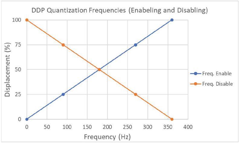
Figure 6 Quantized DDP enabling and disabling frequency outputs.
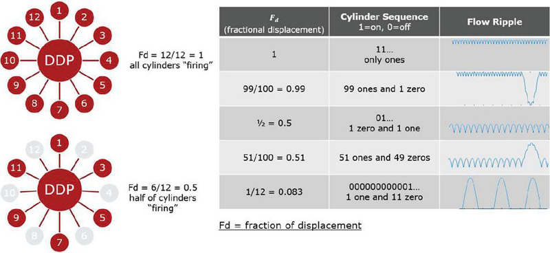
Figure 7 Digital flow control as a delta sigma modulator.
Figure 7 below is used to further explain the concept of enabling and disabling frequencies and their effect on flow ripple. As seen, it is helpful to represent the DDP’s flow algorithm as an analog to digital converter that maps a continuously variable Fd (fractional displacement) to a sequence of digital bits. In this example, when a specific Fd is commanded, the cylinder sequence is represented as a binary output in which “1” indicates a valve firing and “0” represents a valve off (or idling). When observing the associated flow ripple, it is clearly shown to what effect the actively firing and idling valves on its characteristics.
In addition to the Ames HPU, Danfoss had periodic access to a 6-bay HPU at MTS’ facility in Eden Prairie, Minnesota. This HPU dubbed “HPU62” was used for development purposes as well as to provide downstream hydraulic flow for internal test stands at MTS and can be seen below in Figure 8 and a representative hydraulic schematic can be observed in Figure 9. As this was the only accessible 6-bay, all DDP HPU, it was essential in tuning and validating the production intent version of the centralized pressure control software architecture.
A series of controlled displacement sweep tests at 3,000 psi (207 bar) were performed utilizing a servo-controlled load valve downstream of the HPU (not pictured in Figure 8 or 9) Results of these tests are given in Section 3.2.
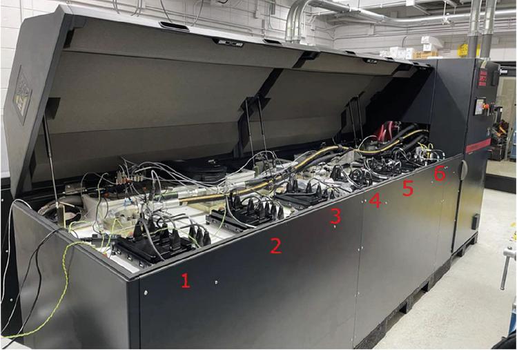
Figure 8 MTS HPU62 (6 bay DDP).
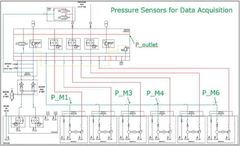
Figure 9 Hydraulic schematic, MTS HPU62.
Frequency spectrum results are shown in Figure 10 below to relay the effectiveness of the centralized pressure control and how quantization changes the frequency profile of the pressure pulsations. The results presented represent data collected on MTS’ HPU62. As previously show in Figure 8, module 1 is the furthest from the control cabinet and consequently has the longest hose length. Due to its length, resonance frequencies generated in this hose were the greatest source of noise and vibration when using the distributed pressure control. Much of the focus and marks of success in applying the Centralized Pressure Control revolved around improving or eliminating resonant frequencies in this module.
Power spectral density of the pressure signals is presented to show the power of the periodic signals in the frequency domain. Also shown are the post-processed average power and average band power of module pressures in the 0 to 100 Hz domain show in Figures 11 and 12 respectively. Using this method allows for a visual and quantifiable representation of the improvements made by the Centralized Pressure Control.
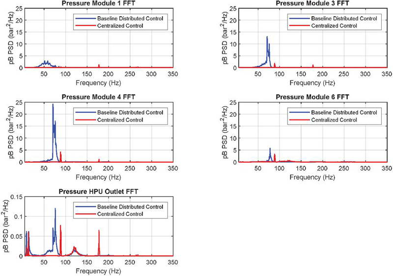
Figure 10 Pressure spectral density FFT results, MTS HPU62.
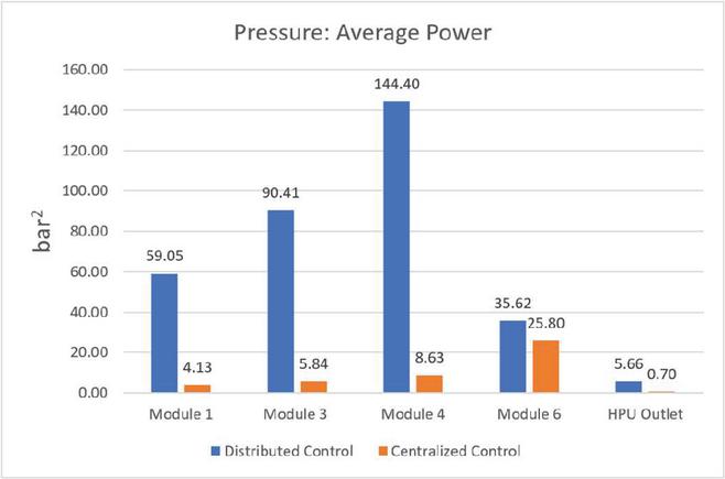
Figure 11 Average signal power (pressure ripple) per module.
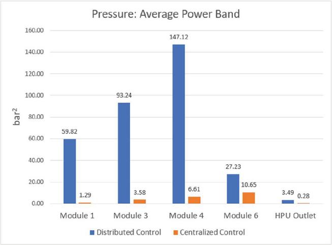
Figure 12 Average band power 100 Hz (pressure ripple) per module.
Table 5 Resulting percent improvement by centralized control
| Location | Pressure: Average Power (bar) | Pressure: Average Band Power (bar) |
| Module 1 | 93% | 98% |
| Module 3 | 94% | 96% |
| Module 4 | 94% | 96% |
| Module 6 | 28% | 61% |
| HPU Outlet | 88% | 92% |
Figures 13 and 14 below show comparative displacement sweep tests from HPU 62. With the distributed control, the peak-to-peak displacement of the pumps was large as each pump controller (DPC12) tried to maintain a pressure setpoint of the DDP it controlled. The result was a high level of pressure ripple. With the centralized control utilizing quantization, a much smoother displacement characteristic could be achieved in addition to decreasing pressure ripple. Table 5 above summarizes the percent improvements achieved by the centralized control. It is not surprising to the see that “Module 6” has a noticeably less improved average power and average band power when compared to the other modules. As mentioned earlier, pump displacement of modules 1 through 5 is discretely variable (quantized) while module 6 has continuously variable displacement.
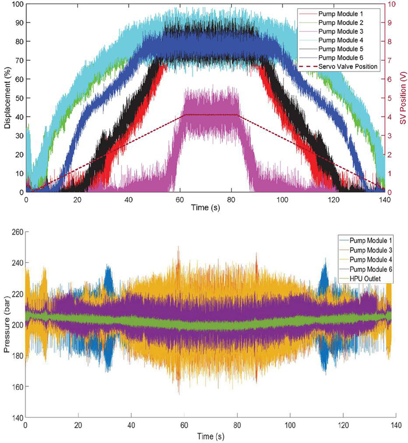
Figure 13 MTS HPU62 (6 DDP) Displacement Sweep with Distributed Control (All modules operate in continuously variable mode).
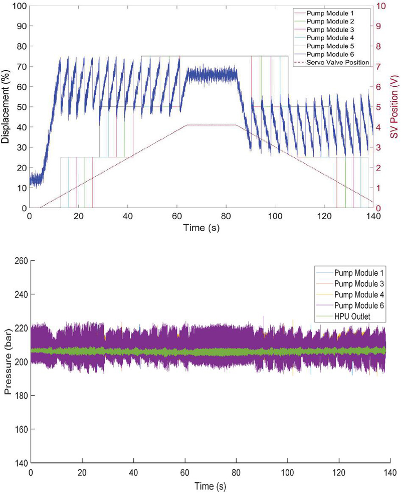
Figure 14 MTS HPU62 (6 DDP) displacement sweep with centralized pressure control (module 6 operates in continuously variable mode while all other modules are quantized).
An energy efficiency study was performed using MTS 329 Test Rig (Figure 15) running a specific repeating drive file. The rig was first powered by HPU61 which is a 6-bay HPU utilizing only swashplate pumps. The output flow, pressure, and total electrical power was recorded over the test duration (10 minutes) and then the test was repeated powered only by HPU62 which as mentioned previously, is a 6-bay HPU utilizing only DDP. HPU62 required 37.5% less electrical energy to produce the same flow.
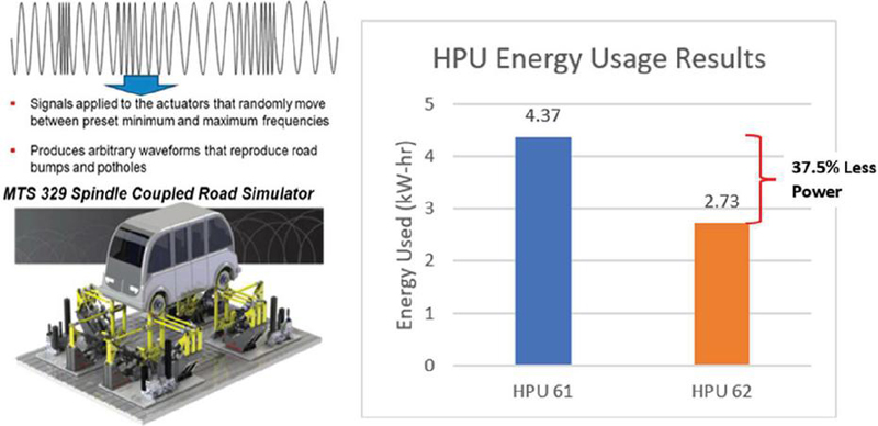
Figure 15 MTS energy audit results.
Over a calendar year of plant operations, HPU 61 and 62 were used to supply the fluid power to the MTS hydraulic distribution system (HDS). By capturing the total kW-hrs of electrical energy the HPUs consumed per day, the hours in operation per day, the total fluid output (in liters) per day, and a consistent pressure setpoint of 3,000 psi (207 bar), the overall energy efficiency of each HPU could be calculated. Figure 16 shows the recorded fluid flow and the related HPU efficiency based on consumed electrical power analysed over the year.
HPU efficiency is the ratio of fluid energy output to electrical energy input. The observed data shows that HPU62 (All DDP) is increasingly more efficient than HPU61 (all swash) as the flow output increases.
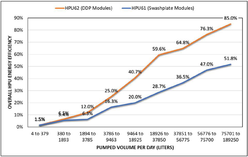
Figure 16 HPU efficiency based on flow output.
As can be seen in the testing results, low frequency pressure pulsations in the 30–80 Hz range were noticeably reduced. As the primary resonance frequencies for the pump modules lie within this range, there was a significant improvement in the control stability of the HPU. There is evidence that the magnitude of some higher frequencies were slightly increased by moving to the centralized pressure control with quantization. However, their influence on the noise and vibration of the HPU was not nearly as noticeable. With quantization, pressure wave energy still exists, but what is there shifts outside of the resonant frequency range of the hoses. This explains the reduction of lower frequency content in Figure 8, in exchange for some increases at higher frequencies.
Noticeable efficiency improvements of HPU 62 (DDP) over HPU 61 (Swashplate) were seen in both a controlled test scenario and in accumulated data over a calendar year. With a lower power consumption compared to swashplate pumps across the displacement range (0 to 100%), the HPUs equipped with DDP benefit from a compounding effect that increases with the number of DDP pumps used. This explains the larger difference between the two HPU’s energy efficiencies as flow increases and the number of active DDP modules increases. As a result, HPUs with DDP can produce more fluid flow per kW-hr of energy consumed.
Due to the operating environment, it was not possible to measure audible noise emitted by the HPUs in the present work. Subjectively, noise level with HPU 62 (DDP) seemed lower than with HPU 61 (swashplate). The authors anticipate an experimental evaluation of this observation in a future measurement.
Speaking of future work, one might inquire about the applicability of Digital Displacement technology to other industrial applications. The subject of the present paper, multi-pump HPU at constant pressure, is a good example of a system where the higher installation cost of DDP is justified by lower operating costs. Economic considerations can be optimized with a hybrid design approach of DDP and swashplate pumps in the same HPU. Other applications where energy use, runtime, and lifetime are high may be good candidates for DDP.
In conclusion, it has been shown through a multitude of tests, and analysis that the centralized pressure control with quantization was able to solve a large potential issue associated with pressure pulsations of DDP in the MTS HPU system. Analysis proves that the control strategy measurably reduced the magnitude of average pressure ripple power by 28% to 94% and the average pressure ripple band power by 61% to 98% depending on the analysed pump module. These pressure pulsations in the resonant frequency range of the hydraulic lines were reduced while still meeting the flow and pressure demands required of the system.
In application, the DDP equipped HPUs showed a 37.5% reduction in energy consumption when compared to a swashplate only HPU in a controlled test scenario. Based on output flow, pressure setpoint, and known energy usage captured over a calendar year of plant operations, efficiency improvements of up to 33% were observed on HPUs with DDP compared to those with swashplate only pumps.
In addition to the authors of this paper, it is important to mention the following individuals for their contributions to the successful implementation of DDP with centralized pressure control at MTS. From Danfoss: Connor Szczepaniak and Andrew Hansen for creating the groundwork of system level control software. Jeremy Edmondson and Jeremie Lagarde for their contributions to quantization implementation. Ruoshui Zhang and Wyatt Brenneman for their development, testing, and implementation of production level software. Luke Wadsley for leading commercial discussions and establishing production agreements. William Funk for his assistance in lab testing and setup. Danfoss Scotland for their support, particularly in assembling DDP hardware and various improvements to DPC12 software. From MTS: Scott Johnson for managing the launch of HPUs equipped with DDP. Ian Kugel for portfolio and production launch efforts. Kurt Kvistberg and Kevin Thurmes for their help in electrical and software integration. Jim Sweet for on-site testing setup and assistance.
[1] U.S. Department of Energy (13 November 2024). Improving Pumping System Performance: A Sourcebook for Industry, 2nd Ed. Publication date May 2006. https://www.energy.gov/sites/prod/files/2014/05/f16/pump.pdf.
[2] Rampen, William. 1992. The Digital Displacement Hydraulic Piston Pump. PhD Thesis. University of Edinburgh. Edinburgh, UK.
[3] Danfoss Power Solutions (13 November 2024). Digital Displacement Data Sheet, DDP096 pump and DPC12 controller. https://assets.danfoss.com/documents/361313/AI332064420016en-000201.pdf.
[4] Williamson, C. and Manring, N. A more accurate definition of mechanical and volumetric efficiencies for Digital Displacement pumps. Proceedings of the ASME/Bath 2019 Symposium on Fluid Power and Motion Control, FPMC2019.
[5] Karnell, S. and Ericson, L. Analysis of a Digital Pump with Variable Speed Drive. Proceedings of the ASME/Bath 2022 Symposium on Fluid Power and Motion Control, FPMC2022.
[6] Huova, M. and Linjama, M. Control of Multi-Pressure Hydraulic Supply Line Using Digital Hydraulic Power Management System. Proceedings of the ASME/Bath 2022 Symposium on Fluid Power and Motion Control, FPMC2022.
[7] Jimenez, C.R., Reinertz, O. and Schmitz, K. A Novel Hydro-Mechanical Control Method for Digital Pumps. The 11th Workshop on Digital Fluid Power. Edinburgh, Scotland, 2022.
[8] Pate, K.; Marschand, J.R.; Breidi, F.; Salem, T.; Lumkes, J. Design and Sensitivity Analysis of Mechanically Actuated Digital Radial Piston Pumps. Processes 2024, 12, 504. https://doi.org/10.3390/pr12030504.
[9] U.S. Department of Energy (13 November 2024). Adjustable Speed DrivePart-Load Efficiency: Energy Tips, Motor System Sheet #11. Publication date November 2012. https://www.energy.gov/eere/amo/articles/adjustable-speed-drive-part-load-efficiency.
[10] Dumnov, D. and Caldwell, N. A cylinder enabling algorithm for reduction in low frequency pulsation from Digital Displacement pumps. Proceedings of the ASME/Bath 2022 Symposium on Fluid Power and Motion Control, FPMC2022.
[11] Szczepaniak, C. and Legarde, J. Hydraulic circuit arrangement and control system for ganged electronically-commutated pumps. PCT patent application WO2022/226026A1, 20 April 2022.
[12] Wiens, T.; Schmidt, M.; Williamson, C. Design of Digital Displacement Pump Systems with Multiple Pumps. Proceedings of the ASME/Bath 2024 Symposium on Fluid Power and Motion Control, FPMC2024.
[13] Pascale, J.; Williamson, C.; Hennen, J.; Rindahl, P. Centralized Pressure Control and Displacement Quantization with Digital Displacement Pumps. Proceedings of the 2024 International Maha Fluid Power Conference. West Lafayette, IN, USA.

Jordan Pascale is a Senior Systems and Applications Engineer at Danfoss Power Solutions in Ames, Iowa, USA. Jordan has 10 years of hydraulic experience related to mobile off-highway machinery and industrial systems. He has a B.S. in Mechanical Engineering from Iowa State University.

Chris Williamson has a Ph.D. degree and 15 years of experience in the fluid power industry. He works as a Senior Specialist Engineer for Danfoss Power Solutions in Ames, Iowa, USA.

Jim Hennen is the senior business development manager for MTS Systems, an ITW company, with responsibility of servohydraulic standard products of power, distribution, actuation, and modular test stands. Jim has 38 years of MTS experience in various senior roles from technical services, field engineering, field & factory service operations management, aftermarket business development, and product development. Jim holds multiple patents. Mr. Hennen is a member of IEEE, AFSMI, and ASTM and holds degrees in electrical engineering (B.S.E.E.) from Southwest University, and a masters in organizational leadership from Augsburg University.

Paul Rindahl is a Senior Engineer at MTS Systems, an ITW company, and is responsible for hydraulic power generation and distribution products. Paul has 18 years of experience in hydraulic power generation, and 7 years of experience as a technician in mobile hydraulic and Diesel repair. He has a B.S. in Mechanical Engineering from North Dakota State University and an A.A.S. in Advanced Caterpillar Technology from Alexandria Technical College.
International Journal of Fluid Power, Vol. 26_2, 163–186.
doi: 10.13052/ijfp1439-9776.2623
© 2025 River Publishers