
A Compensator-less Load Sensing System Designed for Electrified Compact Track Loader
Shaoyang Qu*, Zifan Liu, Rafael Cardoso and Enrique Busquets
Bosch Rexroth, 100 Southchase Blvd, Fountain Inn, SC 29644, USA
E-mail: Shaoyang.qu@bosch.com
*Corresponding Author
Received 17 December 2024; Accepted 27 February 2025
This study introduces an innovative design for the hydraulic implement system in electrified compact track loader applications. The presented architecture is based on a pre-compensated load sensing system, incorporating electronified components and removing one compensator for the boom function. The system employs an electronified open-center pump (eOC-P) and a load sensing pre-compensated valve sourced from Rexroth. The compensator for the boom function is re-designed to remain static, allowing a bidirectional path for regeneration during the boom lowering phase. The eOC-P offers pressure control, flow control, displacement control, and torque control modes, achieved by replacing the traditional mechanical load sensing feedback with sensor signals. A dedicated control strategy is proposed and verified for the compensator-less design to adapt its operational modes to suit both single and multiple user conditions. According to the simulation, the proposed system can achieve the same controllability compared to conventional LS system with energy regeneration capability. From the tests on the proving ground, the novel system performs the same functionality and reduces the power consumption of 37% compared to the baseline open-center system on a 68kW rated power 5-ton compact loader.
Keywords: Electrification, load-sensing system, compensator-less valve, efficiency.
Compact track loaders (CTL) stand as key players in the North American machinery market. In response to increased customer interest and more stringent regulations on exhaust emissions, a notable shift towards electrification has emerged within this sector. The electrification concept outlined in this paper includes the removal of the diesel engine and employing electric-hydraulic powertrain for the implement functions [1]. This shift to a purely electric power source addresses emission concern [2]. However, to unlock the full potential of the electrified powertrain, including energy regeneration, a redesign of the hydraulic system and control strategy is imperative.
In the context of compact loader applications, a predominant source of regenerative energy is derived during the boom lowering phase. In traditional hydraulic systems, when the boom moves downwards, potential energy is typically dissipated at the control valve to regulate its lowering speed. This inefficient operation raises a significant challenge for battery-powered machines, impacting their operational longevity [3]. Thus, it is significant to maximize the usage of the regenerative energy for electrified compact track loader (eCTL).
Decentralization is one popular approach to enable energy regeneration. By employing one prime mover for each actuator, the control system can leverage the electric motor – hydraulic pump speed with minimal throttling losses. Additionally, the implementation of a regeneration mode is facilitated through the combination of a hydraulic motor and an electric generator, assuming the hydraulic machine supports two-quadrant operation [4]. The decentralized architecture has demonstrated notable advantages, with reported energy savings of up to 65% [5], and hydraulic efficiency reaching as high as 84% [6] from the previous research by the author. However, it is essential to acknowledge that while decentralized systems offer efficiency gains, they also pose challenges in terms of increased system costs [7]. This is attributed to the necessity of multiple electric and hydraulic machines to cater to all implement functions of the CTLs. To employ one prime mover for multiple functions, the compensated load-sensing (LS) hydraulic system is usually adopted for mobile applications. A cost-effective approach involves employing a single electric machine to directly drive the LS system, providing an intuitive means to control overall expenses [4]. With an electric drive, it becomes feasible to regulate both the drive speed and pump displacement, optimizing energy performance. Research by Lin. T. et al highlights the benefits of an electric load-sensing (e-LS) system, showcasing a reduction of over 20% in energy consumption through an adaptive variable speed and displacement control strategy [8]. However, a limitation of the LS system lies in its prohibition of energy regeneration, as the compensator only permits flow in one direction – from the pump to the actuator – while backflow is essential for energy recovery. Lin. Z. et al investigated the e-LS system and compared energy consumption between centralized LS systems and decentralized e-LS systems, revealing around 12% fuel savings [9]. Despite these efficiency gains, achieving energy regeneration remained elusive in both configurations. A patented hydraulic system uses extra valves on LS systems to enable energy regeneration [10], but not integrated with the electrified powertrain and a dedicated control algorithm as the authors [11]. Both experimental and simulation methods have been used for electrified hydraulic applications as above regarding the energy performance and controllability, like the studies from Qiu. W. et al for electric heavy duty machines [12, 13].
From the state of the art, the electrification of CTLs presents inherent trade-offs for the hydraulic implement system:
• High costs associated with decentralized architecture, offering enhanced energy performance.
• Absence of energy regeneration and operational inefficiencies with the e-LS system to limit the costs.
This study proposes a novel compensator-less LS system that specifically targets the identified trade-offs. Two pivotal components, the electronified open-center pump (eOC-P) and the modified pre-compensated valve (RM-MPP) sourced from Rexroth, play a crucial role within the electrified compact track loader (eCTL) architecture. A key redesign involves the compensator for the boom function, strategically engineered to remain static, thereby creating a bidirectional path for regeneration during the boom lowering phase [14]. The eOC-P offers pressure control, flow control, displacement control, and torque control modes, accomplished by replacing conventional mechanical load sensing feedback with sensor signals [15].
This paper focuses on two technical challenges with both simulation and experimental methods:
• Design of a novel system architecture based on load sensing system to release the energy regeneration potential of electrified system.
• Simulation and experimental verification of a new control strategy for the compensator-less LS system, combining the concept of pressure control and flow control for multiple hydraulic functions.
The structure of this paper is organized as follows: In Section 2, the design and control strategy of the proposed system are detailed. Section 3 demonstrates the methods for this study, including the simulation model and baseline definition. Section 4 presents the simulation results and corresponding analysis. Finally, Section 5 concludes the study and offers insights into future perspectives.
The reference machine for this study is the Bobcat T770 compact track loader, with the rated power of 68kW, as shown in Figure 1.
Figure 1 Reference vehicle Bobcat T770 compact track loader.
Table 1 lists the key parameters of the reference machine. It is important to note that in the context of this electrification study, the diesel engine, along with all hydraulic and thermal components, has been eliminated from the reference machine This commercial CTL establishes the sizing requirements but also serves as the benchmark for achieving the performance targets outlined in the electrification proof of concept.
Table 1 Main specifications of the reference vehicle
| Specifications | Values |
| Engine Type | 3.4L Bobcat Diesel Engine, 4 cylinders |
| Max power | 92 hp [68 kW] |
| Max Standard flow | 23 gpm [87 L/min] |
| Machine Weight | 10,515 lb [4770 Kg] |
| Engine speed | 1100–2600 rpm |
This paper focuses on the control of two crucial implement functions of the vehicle, boom and bucket actuation. Figure 2 provides the parameters associated with these functions. The reference machine utilizes conventional pre-compensated LS system for its implement functions. Based on the actuation data, the electrified hydraulic system undergoes a redesign, with components sized to meet the demands of the original cycle requests.
Table 2 Parameters of the boom and bucket actuators
| Actuation Parameters | Value [unit] | |
| Boom cylinder and cycle time | Length of stroke | 662.7 [mm] |
| Diameter of piston | 82.6 [mm] | |
| Diameter of rod | 50.8 [mm] | |
| Raising arm time | 4.8 [s] | |
| Lowering arm time | 3.4 [s] | |
| Bucket cylinder and cycle time | Length of stroke | 349.0 [mm] |
| Diameter of piston | 76.2 [mm] | |
| Diameter of rod | 38.1 [mm] | |
| Bucket dump time | 2.34 [s] | |
| Bucket rollback time | 2.05 [s] | |
Figure 2 presents the hydraulic schematic of the implement system for the electrified tracked loader. For the sake of simplification and to maintain focus on the study’s scope, certain elements such as the auxiliary section and functions like parking brake control are excluded from the illustration. The proposed architecture incorporates key components, including the eLION inverter and electric motor as the prime mover, the A10VO eOC unit capable of 4-quadrant operation, and the RM pre-compensated LS valve. Notably, the boom control section is enhanced with a static compensator, a modification crucial for enabling energy regeneration. The modification on the compensator with an extra shim to keep it open statically, but this valve section is still capable with other RM sections without any change on the platform. The schematic emphasizes the inclusion of essential sensors, such as pressure sensors, displacement sensors at the actuators, and the angle sensor of the eOC-P. These sensors play a vital role in providing feedback necessary for effective control.
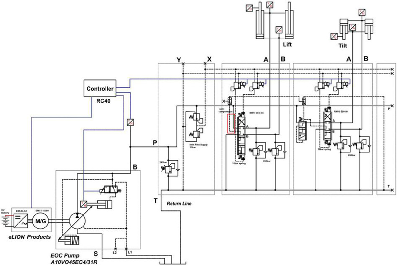
Figure 2 Hydraulic schematic of the proposed system.
Figure 3 provides a visual representation of the working principle behind boom control with energy regeneration. The modification of the compensator to a static, always wide-open configuration allows for the implementation of displacement control for the boom function with the eOC-P capable of 2-quadrant operation, which covers both positive and negative displacement. The velocity of the boom actuation is governed by the pump displacement , dictating the flow rate to the system in both directions. Simultaneously, this controls the power flow to the electric machine and inverter, assuming an unchanged shaft speed. Notably, the valve can be fully opened, a design feature that serves to minimize throttling losses.
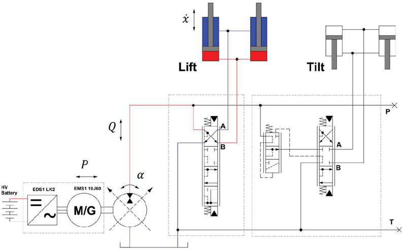
Figure 3 Regeneration capability from the boom function.
The flow rate delivered to the boom actuators is as Equation (1), where is the maximum displacement of the pump.
| (1) |
And the velocity of the boom cylinders follows Equation (2). Thus, the velocity can be controlled by adjusting the pump ratio as given in Equation (3). The ratio could be negative for regeneration mode when the boom cylinders retract with negative too.
| (2) | |
| (3) |
While the example above focuses on boom control in a single-user scenario, the introduced modifications in the LS architecture pose a control challenge when considering multiple-user conditions. Consequently, a novel control strategy is proposed to address this complexity.
Figure 4 illustrates one multiple user condition, wherein both the boom operation and bucket rollback occur at the same time. The compensator of the bucket section regulates he flow rate to the bucket cylinders , and the pump output flow can be controlled using Equation (1). As a result, the flow rate to the boom cylinders is derived as . If the user requires for the boom, the pump flow is controlled according to Equation (4). In contrast to the conventional LS system, the proposed system eliminates the need for a boom compensator, replacing its functionality by directly controlling the pump flow using the eOC-P. Other functions with compensators maintain the same control principles.
| (4) |
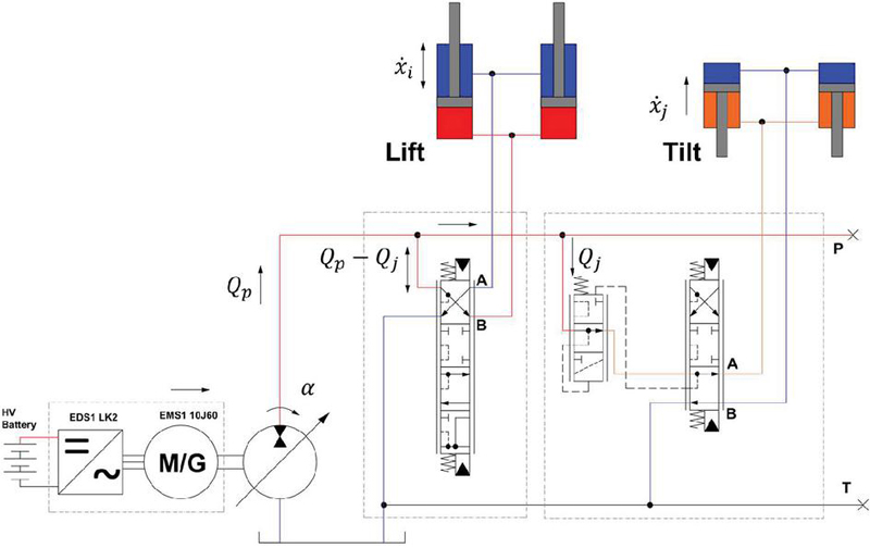
Figure 4 Control strategy for multiple users boom and bucket.
One fact about this tracked loader application is that the load pressure of the boom cylinder tends to be higher than that of the bucket cylinder . Under this scenario, the valve for boom control can be fully opened to optimize efficiency, given that the flow typically aligns with the requests of the compensated bucket function, which operates at a lower pressure. Energy regeneration is feasible when when lowering the boom, utilizing backflow from the boom to fulfill the bucket’s needs. The eOC-P would provide the rest of required flow. Conversely, if , metering control of the boom valve may be applied to meet flow requests during the boom-raising phase. In instances where energy regeneration is not possible during boom lowering, the boom valve section can switch to the PA position, as depicted in Figure 5. The control principle is the same with Figure 4, but this scenario excludes energy regeneration due to the necessity for high pressure during downward boom movements, like in some piling operation. The mode presented in Figure 5 is similar to the conventional LS control in terms of overrunning the boom down but not regenerating from this operation phase.
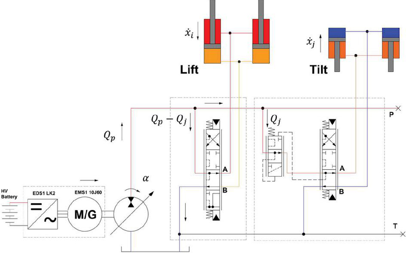
Figure 5 Control strategy for multiple users, lowering the boom without energy recovery.
An alternative method to control the boom lowering involves employing the float section of the valve, as presented in Figure 6. In this scenario, the flow control of the boom floating operates independently of the bucket control. This mode proves advantageous in situations where the load pressure of the boom is low, and energy regeneration is not attainable.
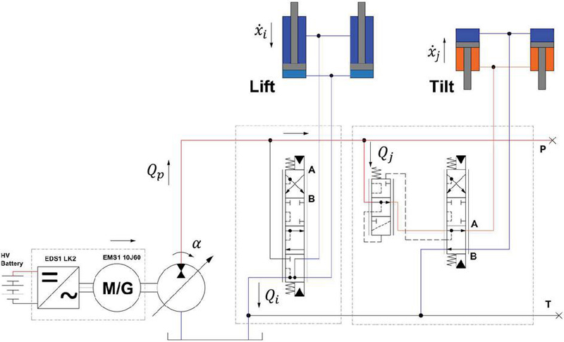
Figure 6 Floating mode of the boom control.
The control strategy is summarized in the flow chart presented in Figure 7. For single-user cases, employing displacement control for the boom is a straightforward approach, facilitating energy regeneration during boom operation. For multiple-user conditions, the compensator associated with the bucket regulates the flow rate along its path, while the pump delivers the required flow for all functions. Under different loading conditions with pressure feedback from the sensors, the controller would command the valve for metering control on boom and bucket actuation under different conditions, aiming to fulfil the functionality with optimal energy performance. For example, if both functions are required, and the bucket loading pressure is higher than that of the boom, the compensator-less valve will need more metering so proper amount of flow will goes to the boom cylinder. If the boom valve is fully opened, all flow would be delivered to the boom due to the compensator-less design and higher pressure at the bucket side. All loading situations are considered, and the proposed system can achieve the same functionality as the conventional LS system. Additionally, the boom section includes a float position designed for lowering the boom under specific conditions.
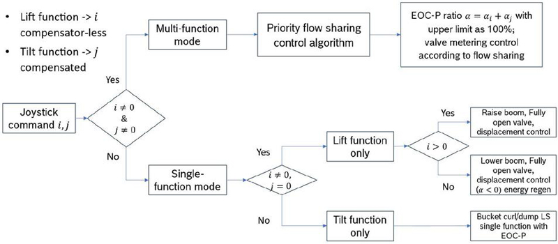
Figure 7 Flow chart of the control strategy for the proposed architecture.
This study adapts both experimental and simulation methods. Initially, the baseline was established through on-field measurements with the reference machine. From the baseline data, a sizing study was conducted to choose suitable components for the proposed system, including the electric machine, hydraulic machine and valves. Subsequently, a lumped-parameter model was developed within AMESIM environment, with specifications of the chosen components as parameters, and baseline data as the model inputs. The simulation model incorporates the efficiency map of the pump and dynamic behaviours of the valves, creating a realistic environment for simulating and fine-tuning the control strategy in preparation for the vehicle demonstration. After the simulation, the proposed system has been installed on the eCTL for the experimental verification on the test field. The tests focus on the actual duty cycle of compact loaders, like the Y-cycle, fast traveling, back dragging and so on, thus the experiments reflect the energy performance and provide and fair comparison to the baseline.
Figure 8 presents a picture of the ongoing experiments of the electrified compact track loader, undertaken at the test field at Bosch Rexroth in Fountain Inn, South Carolina. Various operating conditions were tested, including fast traveling, Y-cycle, gradeability, back dragging, etc. Specifically, the Y-cycle data obtained during these baseline measurements serves as both a reference and inputs for the simulation of the hydraulic implement system.
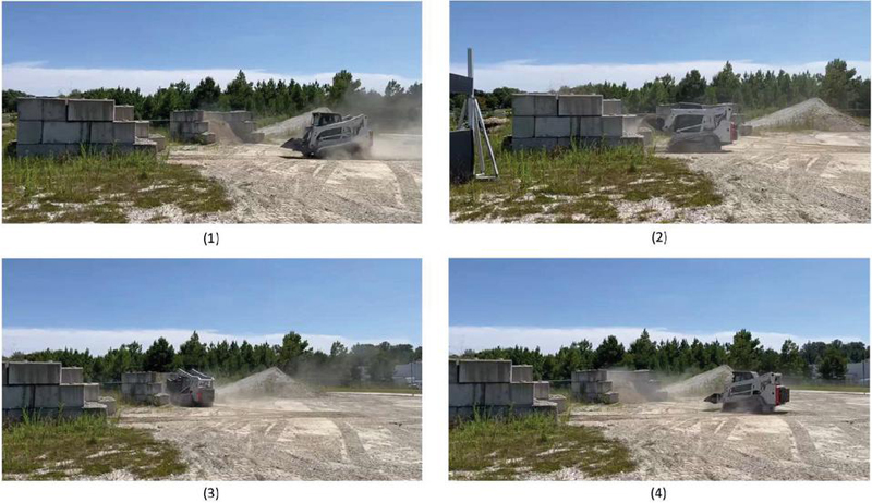
Figure 8 Y-cycle operation of the electrified compact track loader on the test field.
The selected components and product number of those are listed in Table 3, including the Rexroth eLION products, eOC-P and the RM-MMP valve platform.
Table 3 Selected components for the proposed electrified system
| Component | Product Number |
| Electric machine | EMS1-10J60LM7-RSCB-W1M7NNNNN |
| Inverter | EDS1-L0400 KNN-12 ECNM1RDNN-S03RSN9 |
| Hydraulic machine | A10VO0045 EC4 000PL3/60DL VB2 |
| Valve inlet plate | M4-12-2X / J 260 Y |
| Boom section | RM15 S1 S22ZZZ W040-090 H24H24 S00 |
| Bucket section | RM10 S1 S22ZZZ E090-090 H24H24 S00 |
| Auxiliary section | RM15 S1 S22ZZZ E110-110 H24H24 S00 |
| Valve end plate | M4-12-2X / LA |
| Pressure sensors | PR4 280 U7 D SE/10, PR4 050 U7 D SE/10 |
| Parking brake valve | SV08-30-6T-N-24ER |
| Oil filter | 50LE0150-H10XLA00-V2,2-M |
Figure 9 presents the configuration of all components inside the electrified compact track loader. Due to the limited space, it is challenging to integrate the system as presented, considering all sub-systems including propelling, working, cooling, and charging systems. The sizing of all components must be done properly and configured in a subtle way to use every left area inside the machine.
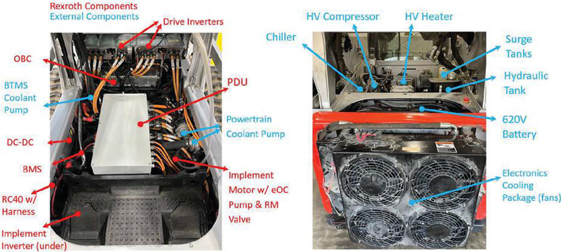
Figure 9 Integration of all components for the eCTL prototype.
A lumped-parameter model was developed in AMESIM environment as depicted in Figure 9, it is evident that the architecture of the model aligns with the schematic illustrated in Figure 2. The selected components have their parameters determined using measured data, ensuring the model reflects realistic performance to the maximum extent. These parameters include the efficiency map and simplified controller of the eOC-P, flow curves with pressure drops associated with the RM valve, and the lookup table of the load force derived from the Y-cycle baseline measurements. The LS-system built in the simulation environment does NOT present the baseline detailed in Section 3.1. The primary outputs of the simulation focus on the functionality of the compensator-less design, and its control algorithm.
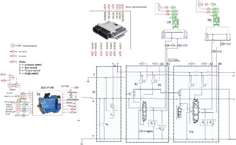
Figure 10 AMESIM simulation model of the electrified implement system.
Regarding the results, the simulation parts focus on the energy regeneration potential of the proposed system as well as the functionality of the proposed control strategy under ideal conditions. As for the experiments, because of the hardware limitation at present, the energy regeneration cannot be fully achieved. Thus, the experimental results emphasize the validation of the novel control algorithm for the compensator-less architecture without energy regeneration, especially for multiple user conditions such as boom and bucket in Y-cycle operations. The energy performance from the tests is presented as well, while the reference is the measured open center system on the baseline vehicle.
Simulation results from AMESIM environment are presented in this section. The plots with null unit are normalized results, like for the operator command and pump angle, from 1 to 1 representing the 100% to 100% of the maximum values. Figure 11 represents an example of the AMESIM simulation results, capturing a complete boom raising and lowering cycle, like the mode illustrated in Figure 3. The first plot showcases the boom command and displacement, while the second provides the eOC-P ratio and the load pressure at the boom cylinder piston side. The third plot displays the power and energy consumption of the hydraulic systems, calculated at the pump shaft.
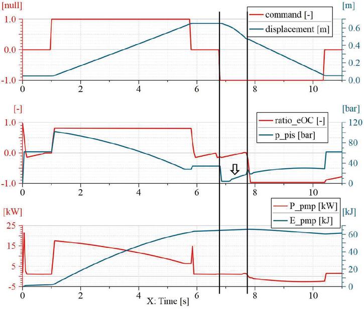
Figure 11 Simulation of one boom cycle with energy regeneration.
From the plots, the boom raising phase extends from 1 s to approximately 6 s, followed by the initiation of the lowering phase around 7 s, persisting for about 4 s. Notably, between the two black lines around 7 s to 8 s, the low load pressure disabled the energy regeneration, activating the float function to lower the boom instead, as indicated in Figure 6. The system requires a minimum of 18 bar for pilot control, meaning energy regeneration is only enabled if the load pressure exceeds this threshold. Beginning at 8 s, the ratio of the eOC unit becomes negative and works as a motor, energy regeneration starts and the power flow reverses direction as indicated in the third plot, until the cycle ends at about 11 s.
For comparison, Figure 12 demonstrates the power and energy consumption in the cycle represented in Figure 11, where the speed command and actual displacement are presented. The baseline is the LS system with standard RM valves with loading conditions from the measurements on the vehicle, so the results should indicate the benefits from the energy regeneration with the electrified powertrain and modified compensator. Comparing the power consumption, the proposed electrified system saves energy during the lowering phase by regeneration. Moreover, because of its compensator-less design, the proposed architecture minimizes the throttling losses and additional energy saving is achieved during the raising phase as well. At approximately 7 s, the baseline system experiences an extra power consumption spike due to insufficient load pressure at the piston side for assistive operation.
Regarding the energy consumption during one boom cycle, as depicted in the second plot, the baseline system records 90.4 kJ compared to the proposed system’s 61.4 kJ, translating to a remarkable 32% energy saving compared to the conventional load sensing system.
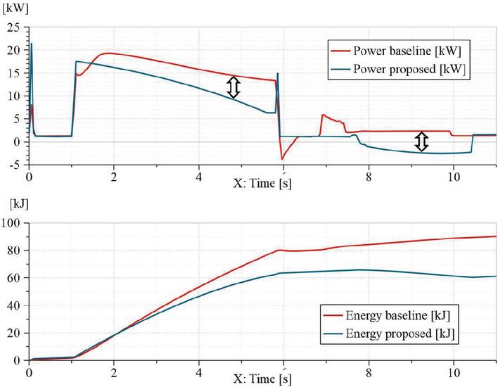
Figure 12 Power consumption comparison from the simulation.
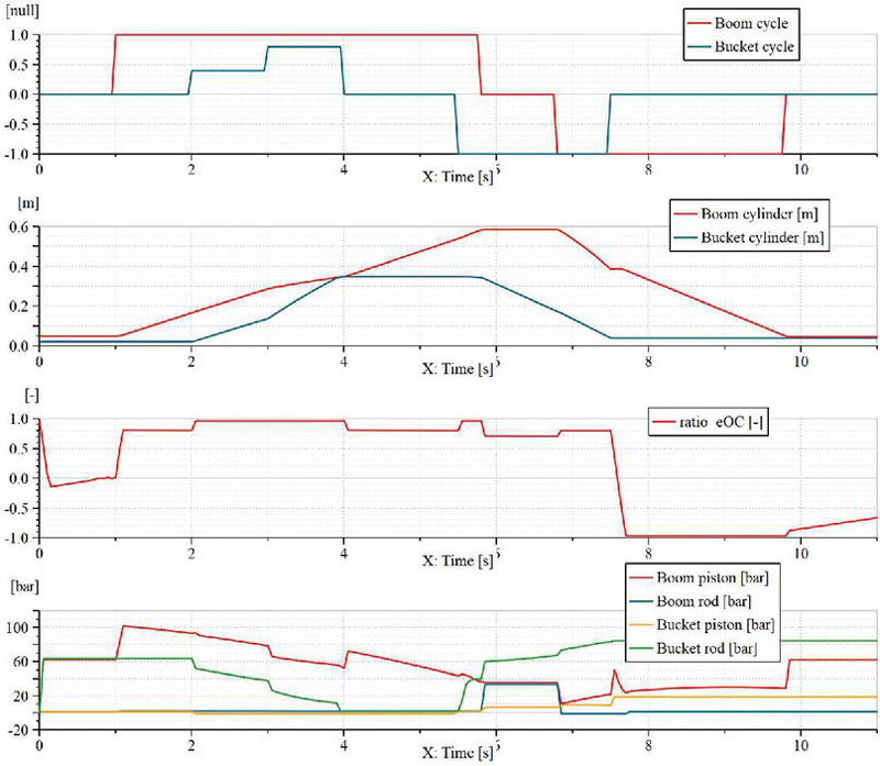
Figure 13 Simulation of the multiple user case, boom and bucket Y cycle operation.
For multiple user conditions, Figure 13 represents the results with boom and bucket Y cycle operation. The first plot provides an overview of the cycle commands, with both actuators being commanded during the time slots of 2 s–4 s and 6.5 s–7.5 s. The second plot illustrates the displacement of the actuators, while the third plot presents the ratio of the eOC-P, offering insights into the flow control dynamics of the system.
During the period from 2 s to 4 s, the system operates in the control mode depicted in Figure 4. The pump is tasked with supplying the required flow for both the boom and the bucket. If the pump ratio reaches 100%, a flow sharing condition occurs, as seen between 3 s to 4 s. In this instance, an increased command to the bucket results in a decrease in the boom velocity. While this paper does not delve into specific control algorithms addressing flow sharing conditions based on user priority, it remains an option for further refinement. From 7 s–7.5 s, the boom drops down and the bucket rolls back. Throughout this time slot, the ratio of the eOC-P remains positive, indicating no energy regeneration with the bucket load pressure higher than that of the boom cylinders. After 7.5 s, the system transitions into regeneration mode, specifically with boom lowering, causing the pump ratio to change to a negative value.
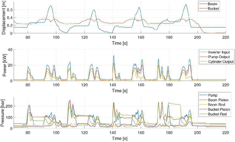
Figure 14 Y-cycle measurements of the eCTL for the implement functions.
From the Y-cycle measurements as shown in Figure 8, Figure 14 indicates the detailed results of the eCTL. The first plot presents the actuator displacement, the second gives the power consumption of the system, and the third summarizes the pressure of the hydraulic system. Figure 14 illustrates typical Y-cycle from a long-term measurement with mixed working cycles, and long run analysis of the eCTL prototype is covered by other work from the same authors.
From the first plot, both boom and bucket functions are under use all the time during the Y-cycle operation. Mostly the boom is moved up and down for the loading/unloading cycles, while the bucket is adjusted slightly to hold or dump the loaded bucket accordingly. This validates the functionality of the control strategy for the compensator-less system. The power plot represents the input power to the inverter, output power of the pump, and the actuation power calculated by velocity and loading force. From the power plot, the efficiency of the hydraulic circuit is about 70% during the operation. It also indicates a combined efficiency of about 80% for the eOC pump and the electric motor. As for the pressure plot, it presents the loading conditions, which is significant for the system control as it requires pressure feedback. From the measurements, the implement system can reach a peak power of about 30 kW and peak pressure of 260 bar.
Figure 15 represents the power consumption of the eCTL from the Y-cycle measurements and compared with the baseline vehicle. Overall, the energy performance of the driving is close, but the implement of the eCTL is more efficient compared to the baseline. The proposed implement system saves more than 37% of power (7.33 kW vs 11.75 kW) during the Y-cycle operation. The remarkable improvement comes from two aspects:
• The baseline machine utilizes the open center system. The pump delivers full flow to the circuit all the time, and the main valve distributes from to actuators or reservoirs. As a result, the energy efficiency of the open center system is low, not as good as conventional LS system.
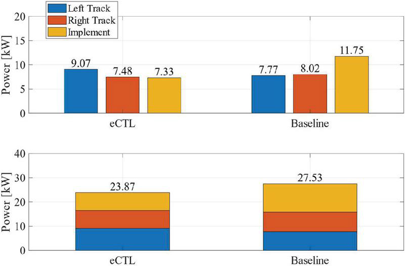
Figure 15 Power consumption of the eCTL and baseline machine from the Y-cycle measurements.
• The proposed system is more efficient than conventional LS system. As the valve has compensator-less design, less throttling losses are expected from the proposed system. The novel control algorithm enables the flow control for some conditions like the single-actuator movement, thus minimizing the losses compared to the LS system.
Regarding the tracking power consumption, it is close between baseline machine (7.77 8.02 15.79 kW) and electric machine (9.07 7.48 16.55 kW). The difference may come from the operator variability and the working conditions. Moreover, the traction system of the eCTL is fully electric and more powerful and responsive than the baseline machine, and it may cause some operation difference. As the traction system is out of scope for this paper, more details would not be given here.
As for the system performance, Figure 16 illustrates the energy flow of the eCTL during the Y-cycle operation. The flow chart gives the energy distribution from the battery to every single function of the eCTL, including the driving and implement as the most consumption, also the low voltage control system and thermal management consumption. From this figure, the overall efficiency and the performance of each sub-system are indicated clearly.
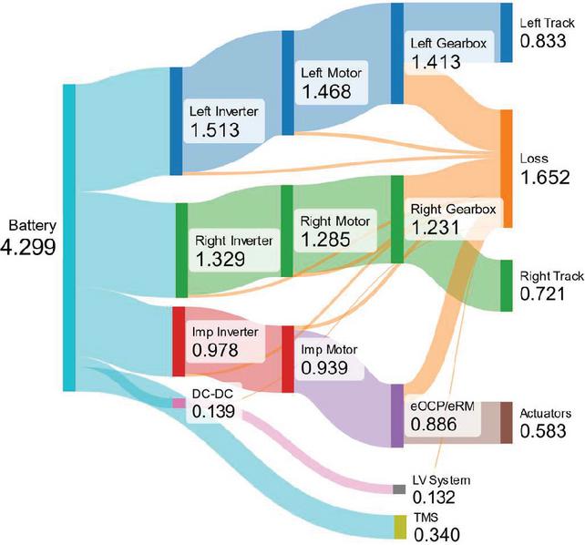
Figure 16 Energy flow distribution of the eCTL, Y-cycle operation.
To be noted, the experimental results presented in this paper only indicate the machine status when submitting the paper, but not the latest or the final results of the eCTL prototype. As the tests are still undergoing with different hardware and software configuration, these results regarding the energy and efficiency performance could be updated accordingly.
In this study, we introduced an innovative electrified hydraulic implement system based on conventional LS architecture. The modification of the boom function’s compensator to a static state facilitates energy regeneration, and a corresponding control strategy has been devised. This strategy employs the capability of the eOC unit, incorporating displacement control and motoring mode to effectively address the complexities associated with multiple user conditions.
To investigate the proposed system, baseline measurements have been conducted on the reference CTL, leading to the selection of suitable components through a comprehensive sizing study. Subsequently, a lumped parameter model was developed in AMESIM environment. Simulation results for multiple user conditions further explore various working modes as proposed, affirming the effectiveness of the control strategy. The boom cycle simulation validates the displacement control strategy, revealing remarkable energy regeneration capability compared to the traditional LS system.
Field tests of the demonstration vehicle has been done on the proving ground, with the common duty cycles such as Y-cycle. The experimental results verify the functionality of the proposed system architecture and the control strategy. An energy saving of 37% of the implement system is found with the Y-cycle operation compared to the baseline machine with the open center hydraulic system. Due to the hardware limitation, the energy regeneration has not been fully released in the tests, which indicates even more potential in terms of the energy saving and efficiency improvement.
[1] Lin, T., Lin, Y., Ren, H., Chen, H., Chen, Q., and Li, Z. (2020). Development and key technologies of pure electric construction machinery. Renewable and Sustainable Energy Reviews, 132, 110080.
[2] Qiu, W., Ashta, S., Shaver, G. M., Mazanec, J., Kokjohn, S., Johnson, S. C., … and Frushour, B. C. (2024). System configuration, control development, and in-field validation of a hybrid electric wheel loader featuring electrically-boosted engine. Control Engineering Practice, 150, 105989.
[3] Lin, T., Chen, Q., Ren, H., Huang, W., Chen, Q., and Fu, S. (2017). Review of boom potential energy regeneration technology for hydraulic construction machinery. Renewable and Sustainable Energy Reviews, 79, 358–371.
[4] Fassbender, D., Zakharov, V., and Minav, T. (2021). Utilization of electric prime movers in hydraulic heavy-duty-mobile-machine implement systems. Automation in Construction, 132, 103964.
[5] Qu, S., Zappaterra, F., Vacca, A., and Busquets, E. (2023). An electrified boom actuation system with energy regeneration capability driven by a novel electro-hydraulic unit. Energy Conversion and Management, 293, 117443.
[6] Qu, S., Fassbender, D., Vacca, A., and Busquets, E. (2021). A high-efficient solution for electro-hydraulic actuators with energy regeneration capability. Energy, 216, 119291.
[7] Qu, S., Fassbender, D., Vacca, A., and Busquets, E. (2021). A cost-effective electro-hydraulic actuator solution with open circuit architecture. International Journal of Fluid Power, 22(2).
[8] Lin, T., Lin, Y., Ren, H., Chen, H., Li, Z., and Chen, Q. (2021). A double variable control load sensing system for electric hydraulic excavator. Energy, 223, 119999.
[9] Lin, Z., Lin, Z., Wang, F., and Xu, B. (2024). A series electric hybrid wheel loader powertrain with independent electric load-sensing system. Energy, 286, 129497.
[10] WO24058689-A1, Hydraulic System, Lejonberg Robert, Maennistoe Ville, (2024). International patent
[11] US patent, E-Load sensing system with compensator-less design, Shaoyang Qu, Rafael Cardoso, Enrique Busquets, (2024), in prosess.
[12] Qiu, W., Ashta, S., Shaver, G. M., Johnson, S. C., Frushour, B. C., and Rudolph, K. (2024). Expediting Hybrid Electric Wheel Loader Prototyping: Real-Time Dynamic Modeling and Power Management Through Advanced Hardware-in-the-Loop Simulation. IEEE Transactions on Vehicular Technology.
[13] Qiu, W., Ashta, S., Shaver, G. M., Johnson, S., and Frushour, B. C. Facilitating the Development of a Novel Heavy-Duty Offroad Vehicle Exploiting Hardware-in-the-Loop Technique. (2024) International Maha Fluid Power Conference. https://doi.org/10.13052/rp-9788770047456.
[14] US2021025414 (AA) – Hydraulic Pressurizing Medium Supply Assembly, Method, And Mobile Work Machine EOC patent, Geiger Daniel, Muehlbauer Florian, Golde Marcel, Brand Michael, An Minha, Tetik Salih, Wang Ximing, (2021).
[15] Qu, S., Liu, Z., Cardoso, R., and Busquets, E. Electrification of a compact skid-steer loader–redesign of the hydraulic functions. (2024) International Maha Fluid Power Conference https://doi.org/10.13052/rp-9788770047456.012.

Shaoyang Qu has been an electrified systems engineer in Bosch Rexroth US since 2022. He is responsible for proposing novel systematic solutions for conventional mobile hydraulics and electrified systems with Rexroth eLION platform. He got the Ph.D. degree in the School of Mechanical Engineering at Purdue University, where he worked in Maha Fluid Power Research Center on electrification of mobile hydraulics since 2018. Before that, he studied in Tsinghua University in Beijing, China, where he received his B.E. in Mechanical Engineering and B.S. in Business administration in 2018. His work mainly focuses on the electrified solutions of the state-of-the-art hydraulic systems and the development of next generation electrification platforms.

Zifan Liu is a senior system engineer specializing in electronics and electrification at Bosch Rexroth. Zifan has been actively involved in the development of the Rexroth eLION electrification platform, contributing to both hardware and software. Zifan assists with customer vehicle commissioning, internal prototype integration and software development, with a focus on next-generation electric system for off-highway applications. Zifan holds a Ph.D. from the Automotive Engineering Department of Clemson University.

Rafael Cardoso brings over 15 years of industry experience as a software engineer, with a specialized focus on embedded programming for off-highway machinery. Throughout his career, he has played a pivotal role in developing and validating innovative efficiency solutions for mobile machinery systems.
He holds a Bachelor’s degree in Agricultural Engineering and a Master’s degree in Control Systems and Automation. Since joining Bosch Engineering in 2015, Rafael has contributed significantly to technological advancements within the company. He currently leads the Software, Systems, and Application Engineering departments at Bosch Rexroth in the United States.
In this leadership role, he leverages his deep technical expertise to drive innovation, enhance operational performance, and establish new benchmarks of excellence. His work continues to strengthen Bosch Rexroth’s position as a global leader in industrial and mobile applications.

Enrique Busquets Vice President Engineering, Service and Aftermarket, Bosch Rexroth North America. Dr. Enrique Busquets is currently responsible for the Bosch-Rexroth Mobile Solutions service, remanufacturing, and aftermarket business in North America. In addition to this current role, Enrique has been responsible for engineering with regional product and business development responsibility on hydraulic pumps, valves, electronics, software, telematics, and electrification in North America since April 2021. Additionally, since 2018, Enrique has been responsible for the testing, validation, and vehicle integration infrastructure in North America.
Previously, Enrique Busquets was the engineering manager responsible for systems and software development at Bosch Rexroth North America from 2018 to 2021. The technology focus was mobile applications with electronified hydraulics and electrified systems.
Enrique holds a bachelor’s degree from the University of Texas at El Paso and a master’s, and doctorate degree in mechanical engineering from Purdue University with emphasis on hydraulics and electronics controls.
In addition to his professional activities, Dr. Enrique Busquets is the Bosch Rexroth industry sponsor and part of the industry advisory board at the Maha research center.
International Journal of Fluid Power, Vol. 26_2, 187–210.
doi: 10.13052/ijfp1439-9776.2624
© 2025 River Publishers