Energy Efficient Excavator Implement by Electro-Hydraulic/Mechanical Drive Network
Lasse Schmidt1,*, Mikkel van Binsbergen-Galán1, Reiner Knöll2, Moritz Riedmann2, Bruno Schneider2 and Edwin Heemskerk2
1AAU Energy, Aalborg University, Aalborg, Denmark
2Bosch Rexroth AG, Lohr am Main, Germany
E-mail: lsc@energy.aau.dk
*Corresponding Author
Received 29 August 2024; Accepted 02 October 2024
Abstract
The focus on electrification of mobile working machines is increasing in industry as well as in the academic community, and ways to realize both technically and commercially feasible solutions are continuously being pursued. At this point, solutions presented by industry has mainly focused on avoiding internal combustion engines by installing cable or battery fed electric motors powering the main pump(s) which supplies the working hydraulics. However, rotary functions are sought powered directly by electro-mechanical drives, not including hydraulics. In this endeavor a main challenge is the operation of linear actuators that remain controlled by hydraulic control valves. The associated throttle losses necessitates large batteries to be compensated or alternatively results in low machine uptimes, potentially rendering electrified machines commercially infeasible. An obvious approach to avoid throttle losses may be the replacement of valve-controlled linear actuators by electro-mechanical solutions in low to medium force applications, whereas heavy duty working machines subject to large forces such as medium/large excavators may benefit from standalone electro-hydraulic primary controlled/variable-speed drives. Utilization of such solutions will substantially increase the energy efficiency due to absent or at least limited throttle losses, and the electric power sharing and electric energy recuperation capabilities offered by common DC-bus’ and batteries. However, such standalone solutions/drives must be able to meet both the required maximum force and maximum speed, and even thought these maximum quantities seldom are required concurrently, these requirements may render the associated motors and inverters somewhat large. Hence, applying such solutions may lower the battery requirements, but require substantial levels of motor and inverter power to be installed, which again may compromise the commercial feasibility. This paper presents a potentially feasible alternative to these solutions for an excavator implement, in the form of an electro-hydraulic/mechanical drive network. This is applied for actuation of three linear implement functions as well as the rotary swing function. The realization of the electro-hydraulic/mechanical drive network involves chamber short-circuiting and electro-hydraulic variable-speed displacement machines enabling electro-hydraulic power sharing. The proposed drive network is compared to a highly efficient standalone dual motor electro-hydraulic drive solution as well as a separate metering valve drive supplied by a battery fed electro-hydraulic pump. Results demonstrate that, compared to the standalone dual motor electro-hydraulic drive solution, the proposed drive network is realizable with similar energy efficiency and hydraulic displacement but less installed motor power and likely less integration effort, rendering this a more sustainable and cost-efficient solution. Finally, besides being realizable with less installed motor power and hydraulic displacement, the proposed drive network shows substantially improved energy efficiency compared to the separate metering valve drive solution.
Keywords: Electro-hydraulic drive networks, energy efficiency, electrification, excavator implement drives.
1 Introduction
The losses of traditional hydraulic working machines are mainly associated with the losses of internal combustion engines (ICE’s) and those of the hydraulic systems. Considering excavators, average ICE and hydraulic system efficiencies of 40% and 30%, respectively, have been reported for a 16t excavator [5], resulting in a total machine efficiency from fuel input til mechanical output of 12%. Hence, major machine level efficiency improvements may be achieved by replacement of ICE’s by battery or cable fed electric machines and associated inverters. Assuming a combined average efficiency of electric machines, inverters and batteries of 80%, the energy consumption is reduced by 50% compared to ICE powered machines emphasizing the importance and significance of electrifying hydraulic working machines.
Even though electrification of such machines is an ongoing trend, the hydraulic systems of such machines remain inefficient due to the continued utilization of throttle control valves.1 As a results, current electrified working machines are subject to either low machine uptimes or large battery capacities, which in either case may render such machines commercially infeasible and prevent the anticipated reduced energy consumption and associated emissions to become reality.
In order to overcome this unfortunate feature, hydraulic system efficiencies must be improved. Even though valve-based system architectures may provide for improved efficiencies compared to traditional valve-controlled systems [1, 2, 3, 4], obvious technologies to consider for energy efficiency improvements are electro-mechanical or electro-hydraulic drive solutions. The former has already been proposed for small and medium sized machines whereas the latter may be a feasible alternative in larger machines. Electro-hydraulic drive research and developments have historically been focused on standalone drives for actuation of hydraulic cylinders and a fairly large number of such drives have been presented in literature, e.g. [6, 7, 8, 9, 10]. Hydraulic working machines typically contain multiple linear and rotary functions realized via hydraulic cylinders and hydraulic motors. However, this far only limited attention has been given to dedicated multi-axis electro-hydraulic drive systems. Only recently this topic has been emerging, and ranges from system solutions combining displacement units in variable-speed and/or displacement-controlled cylinders with valve-controlled cylinders in a mix [11, 12] to more disruptive drive design approaches such as the so-called HHEA [13, 14] and electro-hydraulic (variable-speed) drive networks [15, 17]. The field of electro-hydraulic drive networks offers a tremendous amount of possible drive architectures, and the solution space increases exponentially with the number of hydraulic cylinders or motors to be actuated [15]. Furthermore, electro-hydraulic drive networks enable the possibility to completely avoid the use of throttle control valves, and hence to completely avoid the associated losses. These drive networks may be realized with short-circuited chambers and with the only active components being variable-speed displacement units in network configurations. The absence of control valves and the related conceptual losses, renders such drive networks highly efficient, and the networked drive systems and chamber short-circuits may provide for significantly reduced power installation requirements compared to other electro-hydraulic drive solutions as well as systems based on electro-mechanical actuators [16, 22], also in excavators [19]. The tight interconnections between the individual cylinders/motors of electro-hydraulic drive networks necessitates special consideration on the design foundation [18], and may seem difficult to control from a first glance. However, decoupling control design methods have been developed [17] and experimentally validated [20, 21], showing that such drive networks can indeed be controlled properly, also without the use of advanced nonlinear control methods [23, 24].
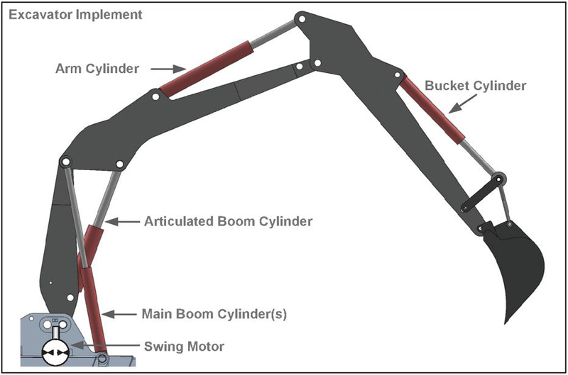
Figure 1 Illustration of excavator implement and the associated boom, arm, bucket cylinders and swing motor.
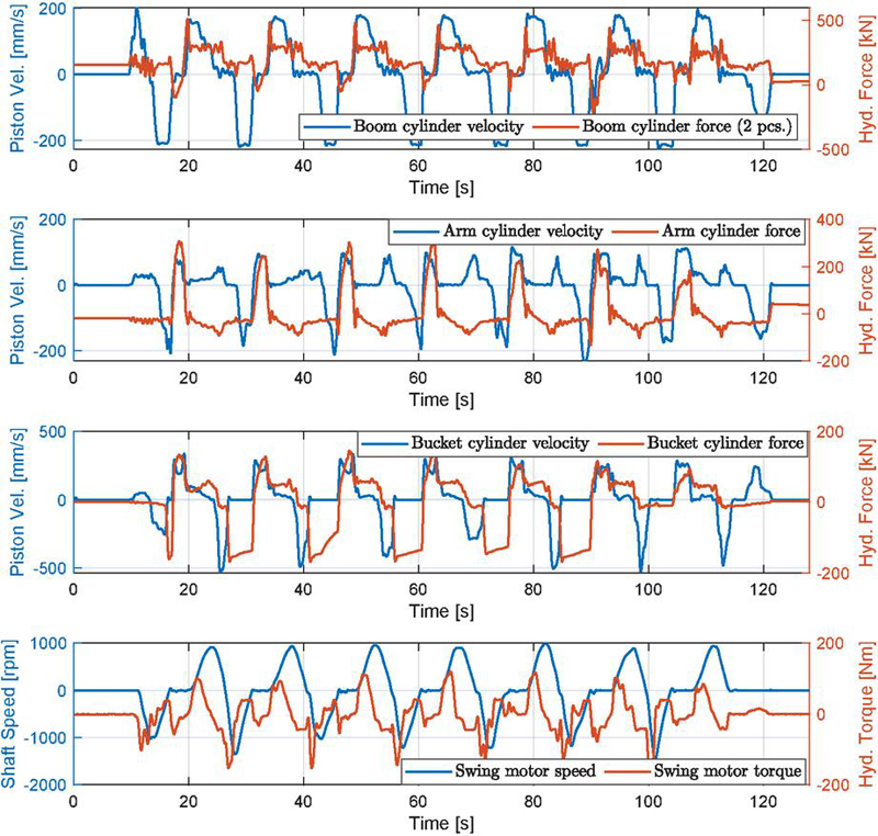
Figure 2 Load cycles for implement cylinder piston and swing motor velocities and hydraulic pressure forces/torque.
This paper presents a novel hybrid excavator implement drive system for actuation of the four axes being the main boom cylinders, the arm cylinder, the bucket cylinder and the swing function of a wheeled excavator depicted in Figure 1, and is an extension to the drive system considered in [19]. Here the articulated boom cylinder is not considered as the associated power transmission is limited compared to that of the main boom, arm and bucket cylinders as well as the swing function. The proposed drive system combines an electro-hydraulic drive network actuating the cylinders and an electro-mechanical swing drive, effectively realizing an electro-hydraulic/mechanical drive network (denoted EDN). The EDN is compared to a drive solution based on dual displacement unit electro-hydraulic standalone cylinder drives, also combined with an electro-mechanical swing drive (denoted DEH), and a drive solution based on individual metering valves supplied by an electro-hydraulic variable-speed pump (denoted SMV). The former (DEH) is based on dual displacement unit standalone electro-hydraulic drives with no conceptual losses and hence one of the most efficient standalone drive solutions realizable. The latter (SMV) may be the most efficient drive solution when applying throttle control valves. Due to the electric power interfaces, all three solutions considered are applicable in battery or cable fed machines. Considering the application, especially wheeled excavators are used for a variety of tasks and subject to idle phases which, for a commercial excavator drive design, should all be considered [3]. In some of these tasks, like leveling of soil, the controllability is of main relevance whereas for other tasks the energy efficiency is most important. The latter is true for digging which is a predominant excavator task. However, for simplicity, the drive designs considered in the following are based on the series of measured digging cycles illustrated in Figure 2 from a representative 17-19t wheeled excavator. From these, the main components are sized with offset in Bosch Rexroth A2 hydraulic displacement units and Bosch Rexroth eLION electric motors. Loss models based on experimental measurements are used to estimate the resulting power consumption and loss distribution, and results suggests the energy efficiency of the EDN to be substantially improved compared to the SMV and comparable to the DEH, but realizable with less installed electric motor power.
2 Electro-Hydraulic/Mechanical Drive Network
The proposed electro-hydraulic/mechanical drive network (EDN) considered for actuation of the excavator implement cylinders and swing function is depicted in Figure 3. The electro-hydraulic part of the drive network is a so-called minimal realizable electro-hydraulic drive network, i.e. it contains the minimal number of displacement machines necessary to enable control of cylinder motions and the system pressure level. The electro-mechanical part of the drive network includes an electric motor shaft connected directly to the gear ring of the excavator undercarriage/cab assembly. As a result, there are five electric motor inputs to control and five outputs in terms of the cylinder velocities, the swing speed and the lower pressure level in the hydraulic system. Furthermore, the proposed EDN is configured with three chambers short-circuited, namely the boom rod side, the arm piston side and the bucket piston side chambers. The consequences of these short-circuiting’s are nearly identical pressures in the short-circuited chambers, resulting from the fact that the fluid can flow nearly unrestricted between these chambers. Consequently, hydraulic power is transmitted nearly loss free between these chambers during simultaneous cylinder motions. The same feature is presented on the electrical side of the system, due to the common DC-bus/supply. Finally, the network configured variable-speed displacement units (VsD’s) allow to control the individual outputs, with this relying on a combined effort of all VsD’s. This topic is not further addressed here, but generally considered in [17, 21].
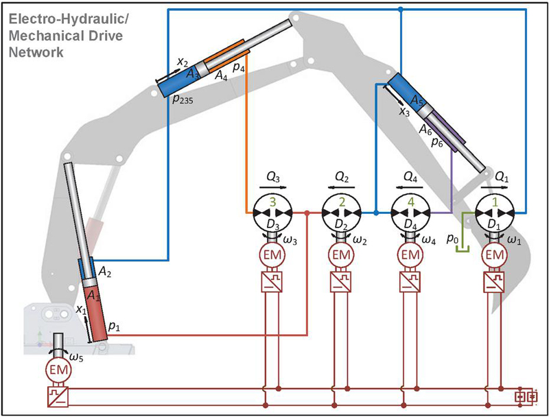
Figure 3 Proposed electro-hydraulic/mechanical drive network (EDN) for excavator implement.
2.1 Flow & Pressure Requirements
In order to size the displacement machines related to the hydraulic side of the EDN and subsequently the electric motors, the associated flows and pressure differences must be determined. This task is conducted assuming steady state conditions, and from a conservative system standpoint, i.e. assuming that no dissipative effects are present. Considering the schematic of Figure 3, the flow continuity equations may under these conditions be expressed as Equations (1)–(3), assuming identical and constant fluid bulk modulii . Assuming steady state conditions the displacement machine flows , , , may be obtained as Equations (4), (5).
| (1) | ||
| (2) | ||
| (3) | ||
| (4) | ||
| (5) |
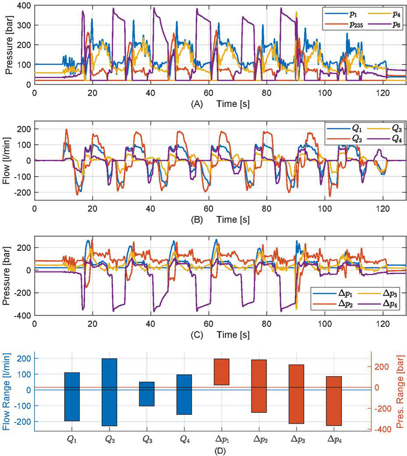
Figure 4 (A) EDN chamber pressures. (B) VsD flows for EDN. (C) VsD pressure differences for EDN. (D) Required ranges for VsD flows and pressure differences with the EDN.
From the constraints induced by the chamber short circuits, the pressure differences related to the displacement machines are given by Equations (6), (7).
| (6) | ||
| (7) |
Applying the load cycles of Figure 2 with Equations (4)–(7), the chamber pressures, displacement machine flows and pressure differences as well as the associated ranges appear as depicted in Figure 4 assuming a minimum pressure 20 [bar] is always present in any volume.
3 Benchmark Drive Systems
The two benchmark drive systems mentioned in the Introduction are chosen from their applicability in electrified machines, but also their ability to operate under similar conditions as the EDN in terms of controlling the piston motions and pressure levels. In addition, the benchmark systems may be considered some of the most efficient system topologies within their respective areas, i.e. standalone variable-speed electro-hydraulics and valve controlled hydraulics.
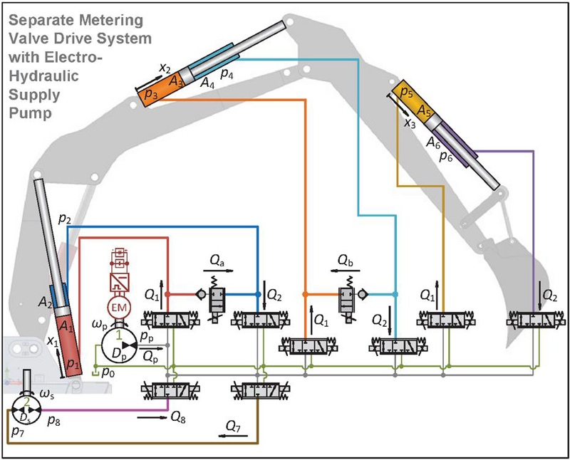
Figure 5 Separate metering valve drive system with electro-hydraulic supply (SMV).
3.1 Benchmark Drive System # 1 – Separate Metering Valve Control
The benchmark drive system based on separate metering valve control (SMV) is depicted in Figure 5. Besides the separate metering control functionality, the drive system also includes flow regenerative valves on the boom and arm functions, and is supplied by an electro-hydraulic variable-speed pump with electric load-sensing functionality.
The valve flows are obtained in a way similar to the displacement machine flows of the EDN, i.e. from the steady state flow continuity equations, and are given by Equations (8)–(11). Here [bar] and [mm/s].
| (8) | ||
| (9) | ||
| (10) | ||
| (11) |
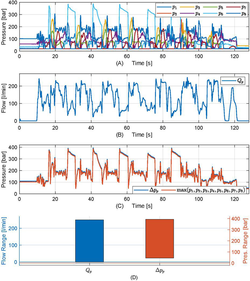
Figure 6 (A) SMV chamber pressures. (B) VsD flow for SMV. (C) VsD pressure difference for SMV. (D) Required ranges for VsD flow and pressure difference with the SMV.
The pump flow is given by Equation (12), i.e. given by the sum of flows entering the cylinders and the hydraulic swing motor.
| (12) | ||
| (13) | ||
| (14) | ||
| (15) | ||
| (16) |
The pump outlet pressure is assumed to be controlled via electric load sensing, and adjusted according to Equation (17). Here [bar] is the pressure overhead necessary to enable valve control under all possible loads.
| (17) |
From Equations (8)–(17) and the load cycles in Figure 2, the corresponding chamber pressures, pump flow and pressure difference and related ranges are depicted in Figure 6 using a minimum pressure of 20 [bar] in the cylinder chambers.
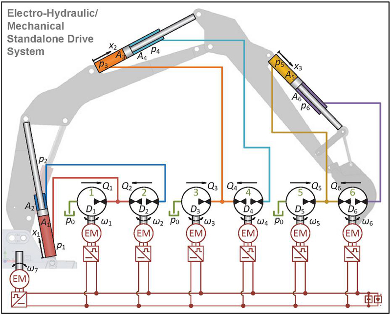
Figure 7 Drive system based on dual pump electro-hydraulic standalone drives (DEH’s).
3.2 Benchmark Drive System # 2 – Standalone Electro-Hydraulic Control
The benchmark drive system based on standalone electro-hydraulic control utilizes the dual displacement machine configuration with two electric motors per cylinder as depicted in Figure 7, while leaving the swing drive purely electro-mechanical as for the EDN. As discussed in the Introduction, this drive system (DEH) is not subject to conceptual losses at all, and may therefore be considered highly efficient compared to many other standalone-type electro-hydraulic drives introduced in literature. This drive system shares the electric supply across all the VsD’s and the swing drive similar to the proposed EDN. The flows and pressure differences of the displacement machines may be obtained as Equations (18)–(21) using the steady state flow continuity equations.
| (18) | ||
| (19) | ||
| (20) | ||
| (21) |
Combining Equations (18)–(21) with the load cycles of Figure 2, the chamber pressures, displacement machine flows, pressure differences and associated ranges appear as shown in Figure 8, again assuming a minimum pressure of 20 [bar].
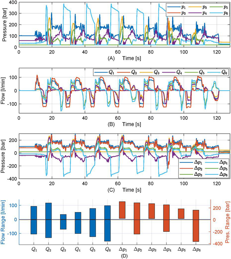
Figure 8 (A) DEH chamber pressures. (B) VsD flows for DEH. (C) VsD pressure differences for DEH. (D) Required ranges for VsD flows and pressure differences with the DEH.
4 Implement Drive Component Sizing
The sizing of VsD components is based on the ranges of flows and pressure differences presented in the previous sections. The swing drive requirements are based directly on the speed and torque specified in Figure 2, while assuming the friction torque of the hydraulic swing motor negligible compared to the friction of the rotary gear ring of the excavator undercarriage/cab assembly. Furthermore, the leakage of the hydraulic swing motor is assumed negligible in the following.
4.1 Sizing of VsD Displacement Machines
The sizing of the VsD displacement machines is based on the Bosch Rexroth A2 bent axis pump and motor series [25, 26], and are considered here due to their proven application history. For any of the considered displacement machines which are not connected to a vented fluid reservoir, the suction restrictions are not violated as a result of the assumption of a minimum pressure level of 20 [bar]. For this reason, displacement machines operating under these conditions may be used in all four quadrants, and therefore these are chosen as A2FM hydraulic motors. Displacement machines connected directly to a fluid reservoir are subject to suction restrictions, hence only operable in two quadrants, and therefore these machines are chosen as A2FO hydraulic pumps. In addition, when fluid is pumped from a vented reservoir into a pressurized control volume, cavitation may occur in the suction port. As a results of this the A2FO sizing’s are based on the maximum positive flow requirements. Finally, flow losses are not included in the sizing, and therefore this task is based on nominal shaft speeds but with an upper limit of 6000 [rpm].
The displacement machine sizes chosen for the three drive systems are shown in Figure 9 along with the total geometric displacements to be installed. Here, the EDN and DEH are subject to reduced installed displacements by nearly 9% and 10%, respectively, compared to the SMV, whereas the difference in total displacement among the EDN and DEH is owed to the available component range.
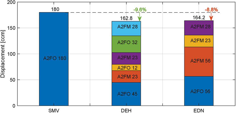
Figure 9 Summary of chosen (VsD) displacement units and total displacements for the three drive systems.

Figure 10 Required max. electric motor speeds and torques for the three drive systems.
4.2 Sizing of Electric Motors
Based on the displacement machine sizes presented in Figure 9 and the load of the swing function shown in Figure 2, the ideal shaft speed and torque requirements for the electric motors are established as shown in Figure 10.
The electric motors are sized using the S2 torques as the maximum design torques and the shaft speeds well below the maximum motor speeds, while not including the flow and torque losses related to the displacement machines. Considering the Bosch Rexroth eLION EMS1 motor portfolio and the electric motor requirements in Figure 10, the motor choices are presented in Figure 11 along with the resulting total rated motor power for each drive system.
The deviations in the total rated motor power results especially from either relatively high required torques or the use of a relatively large number of VsD’s. In case of a high maximum motor torque, the associated rated power tends to be correspondingly large as well, attributed the associated speed range of the electric motor. Similarly, the use of a relatively large number of VsD’s tends to result in a relatively large total installed torque overhead, with this increasing with the number of VsD’s applied. A reasonable level of installed torque and power is therefore achieved with few units and with a reasonable ratio between required speed and torque for each unit.
In summary, the total rated motor power for the EDN is 16.1% lower than the DEH and 29.7% lower than for the SMV. This is attributed less number of VsD’s applied compared to the DEH and, indirectly, to the substantially lower torque requirement compared to the SMV.
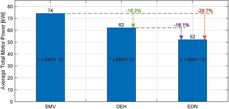
Figure 11 Choice of eLION motors EMS1 along with the resulting total rated (motor) power to be installed.
4.3 Tank Sizing Considerations
Besides the component sizes and the associated material usage, another important aspect from a sustainability standpoint is the amount of fluid required for the drive systems, which is related to sizes of the fluid reservoirs/tanks. Neither the EDN nor the DEH rely on throttle control, meaning that the fluid degasification and fluid cooling requirements are substantially reduced compared to the SMV. The only throttling present in the EDN and DEH drive systems are associated only with cross-port leakage and drain flows, whereas it is the pump flow that is throttled with the SMV.
A rule of thumb suggests that the tank volume should be three times the average (throttled) flow to allow for appropriate heat dissipation and fluid degasification.2 Based on this, the theoretical SMV tank size may be obtained as Equation (22), and applying the same rule for the EDN and the DEH while accounting for the cylinder piston volumes, the associated theoretical tank sizes are obtained from Equation (23).
| (22) | ||
| (23) | ||
Using the loss models described in Section 5, the resulting theoretical tank volumes appear as depicted in Figure 12. Evidently, the theoretical EDN and DEH tank volumes are dramatically reduced compared to the SMV, in both cases by more than 90%. Traditional tank designs used in mobile working machines are often optimized in various ways, and could be as low as half of the volume proposed for the SMV. In such a case, the theoretical reduction in EDN and DEH volumes still exceed 80% compared to the SMV.
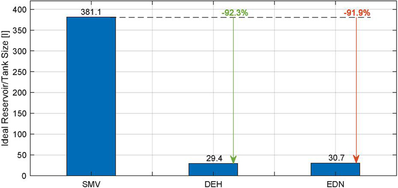
Figure 12 Ideal fluid reservoir/tank sizes and relative reduction compared to SMV.
5 Energy Efficiencies & Loss Distribution
Based on the chosen component sizes for the proposed EDN and the benchmark drive systems SMV and DEH, their energy efficiency and loss distributions are considered in the following along with the loss models applied for the analyses.
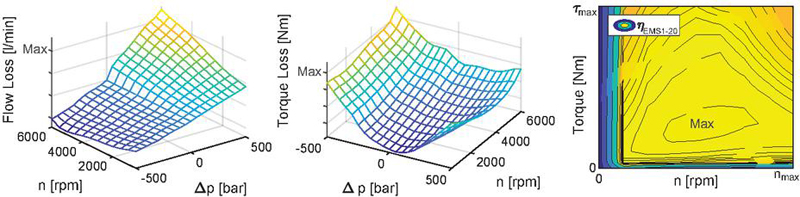
Figure 13 Approximate loss diagrams. Left plot: 2Q flow loss map for A2FMM 32. Center plot: 2Q torque loss map for A2FMM 32. Right plot: Power loss map for eLION EMS1-20 component series motor.
5.1 Loss Models Used in Case Studies
Regarding the loss model used for the displacement machines, this is based on a measured loss map for an A2FMM 32 hydraulic motor, with this assumed representative also for the A2FO units. To account for the different sizes of the displacement units, the measured losses A2FMM 32 are scaled according the scaling rules applied in [7, 15]. The loss model used for the eLION EMS1’s is based on measured losses of an EMS1-20 type motor. In all cases, the measured data has been smoothened to mitigate the impact of outlier measurement points, and the hydraulic losses extrapolated for pressure differences above 350 [bar]. Hence, the loss models applied represent the approximate losses of the components in consideration, and their maps are depicted in Figure 13. Regarding the loss model of the A2FM depicted in Figure 13, the measured flow losses account for both cross-port leakage and drain flows. The scaling of the EMS1 assumes that the efficiency map is invariant with respect to the motor size i.e., that all the EMS1 motors considered have the same efficiency map as the EMS1-20, with the axes scaled to the max. torque and speed of the EMS1 motor in consideration. Furthermore, for the EMS1 motors it is assumed that the efficiency map is valid for all four quadrants. The total inverter losses and DC-bus losses are estimated as Equations (24), (25). Here and are the electrical resistance and nominal current of the inverter, respectively, and , 700 [Vdc] are the electrical DC-bus resistance and the DC-bus voltage, respectively. Furthermore, is the nominal DC-bus current. Finally, the inverter, DC-bus and battery efficiencies are assumed to be 0.98 [-], 0.98 [-] and 0.90 [-], respectively.
| (24) | ||
| (25) |
5.2 Loss Distribution & Power Consumption
From the load cycles of Figure 2 and the loss models described above, the overall average loss distribution for the three drive systems appear as depicted in Figure 14. From these results it is evident that significant reductions in all losses are achieved with DEH and EDN drives compared to the SMV, except for the friction losses. The relatively higher friction losses of the DEH and EDN are attributed the use of more displacement machines compared to the SMV, as well as the associated specific loads.
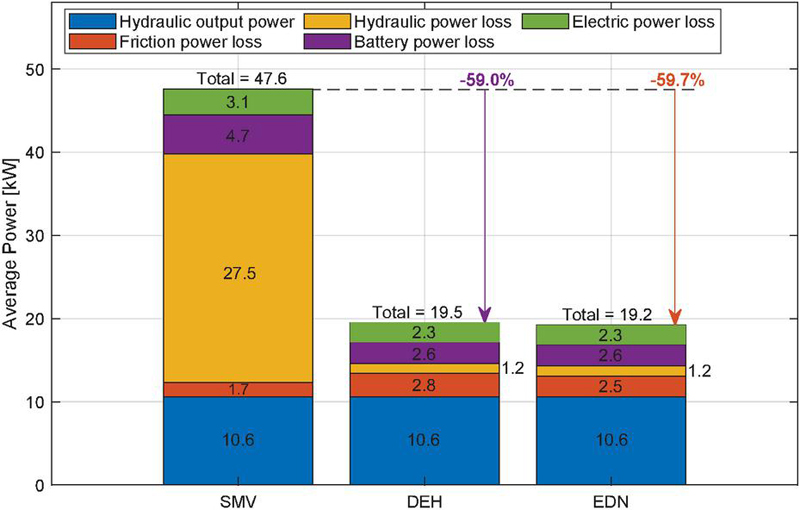
Figure 14 Average losses and average total power consumption.
Furthermore, it is notable from Figure 14 that the average energy consumption by the DEH and EDN drives is reduced by more than 59% compared to the SMV. Hence, assuming the considered load cycles generally representative for the excavator implement, then to conduct an 8 hour shift the required battery capacities would be approximately 381 [kWh], 156 [kWh] and 154 [kWh] for the SMV, DEH and EDN, respectively.
Finally, the drive energy efficiencies in terms of the ratio between the average battery power and the average hydraulic piston power, for the SMV, DEH and EDN are 22.3%, 54.4% and 55.2%, respectively. Hence, the DEH and EDN systems enable energy efficiencies more than 2.4 times higher than that of the SMV.
6 Conclusion
A novel hybrid electro-hydraulic/mechanical drive network for actuation of excavator implements is proposed, involving the linear boom, arm and bucket functions as well as the rotary swing function. The proposed drive network includes short circuiting of three cylinder chambers, namely the boom cylinder rod side chambers and the arm and bucket piston side chambers. As a result, the three cylinders effectively involve only four control volumes, as opposed to the conventional six volumes. The swing function is purely electro-mechanically actuated, and with four VsD’s related to actuation of the control volumes, the electro-hydraulic/mechanical drive network applies five variable-speed displacement units in order to control the individual actuator motions as well as the hydraulic system lower pressure.
The proposed electro-hydraulic/mechanical drive network is compared to two alternative drive systems applicable in electrified machinery, with these being a separate metering drive system supplied by a variable-speed fixed displacement pump and a dual pump electro-hydraulic standalone drive system. Here, the latter also involves an electro-mechanical swing function similar to the proposed drive network. The component requirements for the three drive systems are established, and components subsequently chosen from the Bosch Rexroth A2 hydraulic pump and motor series as well as the eLION electric motor series. Subsequently, steady state models utilizing measured component losses are used to predict the power consumption and loss distribution.
The results suggest that the proposed electro-hydraulic/mechanical drive network is similar to the dual pump electro-hydraulic standalone drive system in terms of energy efficiency and total displacement, whereas the electro-hydraulic/mechanical drive network is realizable with 16% less installed motor power by comparison. Compared to the separate metering drive system, the electro-hydraulic/mechanical drive network reduces power consumption by nearly 60%, increases the total efficiency from 22% to 55% and is realizable with 9% less installed displacement, 30% less installed motor power and a tank volume reduction of more than 80%. The results emphasize the potential significance of electro-hydraulic drive networks in the ongoing efficiency improvements of hydraulic working machines as well as their electrification.
Biographies
[1] J. Weber and B. Beck and E. Fischer and R. Ivantysyn and G. Kolks and M. Kunkis and H. Lohse and J. Lübbert and S. Michel and M. Schneider and L. Shabi and A. Sitte and J. Weber and J. Willkomm. Novel System Architectures by Individual Drives. Proceedings of the 10th International Fluid Power Conference (10. IFK 2016), 2016.
[2] M. Huova and J. Tammisto and M. Linjama and J. Tervonen. Fuel Efficiency Analysis of Selected Hydraulic Hybrids in a Wheel Loader Application. Proceedings of the BATH/ASME Symposium on Fluid Power and Motion Control, 2018. https://doi.org/10.1115/FPMC2018-8869.
[3] A. Sitte and J. Uhlmann and J. Weber and B. Meitinger and und Y. Weidner. Model Based Efficiency Analysis of Mobile Hydraulic Machinery - On The Example of Material Handling Machines. Proceedings of the 10th JFPS International Symposium on Fluid Power (JFPS), 2017.
[4] K. Heybroek. On Energy Efficient Mobile Hydraulic Systems With Focus on Linear Actuation. PhD Thesis, Linköping University, Fluid and Mechatronic Systems, Faculty of Science & Engineering, 2017. https://doi.org/10.3384/diss.diva-142326.
[5] Danfoss. Roadmap for Decarbonizing Cities. Danfoss Impact, Issue no. 3. https://cdn.sanity.io/files/5zabm86v/production/0397994639d425772172c5dec4f83180a9095ad4.pdf (assessed 14-08-2024).
[6] K.J. Jensen and M.K. Ebbesen, M.R. Hansen. Novel Concept for Electro-Hydrostatic Actuators for Motion Control of Hydraulic Manipulators. Energies, 14:6566, 2021. https://doi.org/10.3390/en14206566.
[7] D. Padovani and S. Ketelsen and D. Hagen and L. Schmidt. A Self-Contained Electro-Hydraulic Cylinder with Passive Load-Holding Capability. Energies, 12:292, 2019. https://doi.org/10.3390/en12020292.
[8] P. Casoli and F. Scolari and T. Minav and M. Rundo. Comparative Energy Analysis of a Load Sensing System and a Zonal Hydraulics for a 9-Tonne Excavator. Actuators, 9:39, 2020. https://doi.org/10.3390/act9020039.
[9] L. Schmidt and S. Ketelsen and D. Padovani and K.A. Mortensen. Improving the Efficiency and Dynamic Properties of a Flow Control Unit in a Self-Locking Compact Electro-Hydraulic Cylinder Drive. Proceedings of the ASME/BATH Symposium on Fluid Power and Motion Control, 2019. https://doi.org/10.1115/FPMC2019-1671.
[10] S. Ketelsen and S. Michel and T.O. Andersen and M.K. Ebbesen and J. Weber and L. Schmidt. Thermo-Hydraulic Modelling and Experimental Validation of an Electro-Hydraulic Compact Drive. Energies, 14:2375, 2021. https://doi.org/10.3390/en14092375.
[11] D. Fassbender and V. Zakharov and T. Minav. Utilization of electric prime movers in hydraulic heavy-duty-mobile-machine implement systems. Automation in Construction, 132, 2021. https://doi.org/10.1016/j.autcon.2021.103964.
[12] D. Fassbender and C. Brach and T. Minav. Experimental Investigations of Partially Valve-, Partially Displacement-Controlled Electrified Telehandler Implements. Actuators, 12:50, 2023. https://doi.org/10.3390/act12020050.
[13] J. Siefert and P.Y. Li. Optimal Control of the Energy-Saving Hybrid Hydraulic-Electric Architecture (HHEA) for Off-Highway Mobile Machines. IEEE Transactions on Control Systems Technology, 30:5, 2022. https://doi.org/10.1109/tcst.2021.3131435.
[14] A.A. Khandekar and J. Siefert and P.Y. Li. Co-Design of a Fully Electric Hybrid Hydraulic-Electric Architecture (FE-HHEA) for Off-Road Mobile Machines. Proceedings of the American Control Conference, 2021. https://doi.org/10.23919/acc50511.2021.9482615.
[15] L. Schmidt and K.V. Hansen. Electro-Hydraulic Variable-Speed Drive Networks—Idea, Perspectives, and Energy Saving Potentials. Energies, 15:1228, 2022. https://doi.org/10.3390/en15031228.
[16] L. Schmidt and S. Ketelsen and K.V. Hansen. Perspectives on Component Downsizing in Electro-Hydraulic Variable-Speed Drive Networks. Proceedings of the BATH/ASME Symposium on Fluid Power and Motion Control, 2022. https://doi.org/10.1115/FPMC2022-89547.
[17] L. Schmidt and S. Ketelsen and K.V. Hansen. State Decoupling & Stability Considerations in Electro-Hydraulic Variable-Speed Drive Networks. Proceedings of the BATH/ASME Symposium on Fluid Power and Motion Control, 2022. https://doi.org/10.1115/FPMC2022-89548.
[18] M. van Binsbergen-Galán and L. Schmidt. Determination of Load Collective for Sizing of a Hydraulic Drive Network System Considering Simultaneity Between Actuator Loads. Proceedings of the ASME/BATH Symposium on Fluid Power and Motion Control, 2023. https://doi.org/10.1115/FPMC2023-109823.
[19] L. Schmidt and M. van Binsbergen-Galán and R. Knöll and M. Riedmann and B. Schneider and E. Heemskerk. Energy Efficient Excavator Functions Based on Electro-hydraulic Variable-speed Drive Network. Proceedings of the 14th International Fluid Power Conference (14. IFK 2024), 2024. https://doi.org/10.13052/rp-9788770042222C66.
[20] L. Schmidt and M. van Binsbergen-Galán. Electro-Hydraulic Variable-Speed Drive Network Technology - First Experimental Validation. Energies, 17(13):3192, 2024. https://doi.org/10.3390/en17133192.
[21] L. Schmidt and M. van Binsbergen-Galán. Experimental Validation of a State Decoupling Method Applied to a Dual Cylinder Electro-Hydraulic Variable-Speed Drive Network. Proceedings of the BATH/ASME Symposium on Fluid Power and Motion Control, 2024.
[22] M. van Binsbergen-Galán and L. Schmidt. Experimental Investigation of Hydraulic Power Sharing Potential in a Dual Cylinder Electro-Hydraulic Variable-Speed Drive Network. Proceedings of the BATH/ASME Symposium on Fluid Power and Motion Control, 2024.
[23] L. Schmidt and T.O. Andersen. Application of Second Order Sliding Mode Algorithms for Output Feedback Control in Hydraulic Cylinder Drives with Profound Valve Dynamics. Elektrotechnik und Informationstechnik, 133(6), 2016. https://doi.org/10.1007/s00502-016-0425-7.
[24] J. Koivumäki and J. Mattila. Stability-Guaranteed Impedance Control of Hydraulic Robotic Manipulators. IEEE/ASME Transactions on Mechatronics, 22(2), 2017. https://doi.org/10.1109/TMECH.2016.2618912.
[25] Bosch Rexroth AG. Axial Piston Fixed Pump A2FO, RE 91401/06.2012. Bosch Rexroth AG, 2012.
[26] Bosch Rexroth AG. Axial piston fixed motor A2FM/A2FE series 70, RE 91071/2021-05-17. Bosch Rexroth AG, 2021.
Biographies

Lasse Schmidt received the M.Sc. degree in engineering (mechatronics) from Aalborg University, Denmark, in 2008. From 2008 he was with the application engineering group of Bosch Rexroth A/S, Denmark, and from 2010 an industrial Ph.D. fellow also associated with Aalborg University. He received the Ph.D. degree in robust control of hydraulic cylinder drives in 2014. Subsequently, he has been a postdoctoral researcher at AAU Energy while concurrently being with Bosch Rexroth AG. Hereafter he became an Assistant Professor with AAU Energy. He is currently an Associate Professor with AAU Energy and heading research activities related to electro-hydraulic drive network technology, a field in which he is the founder of the fundamental design and control principles. He is the main author or co-author of nearly 70 scientific peer-reviewed publications, most of them on topics related hydraulic drives and systems control. Lasses current research interests are in design and control of electro-hydraulic drive networks and their integration into both mobile working machines and industrial systems.

Mikkel van Binsbergen-Galán received the B.Sc. and M.Sc. degrees, both from Aalborg University, Denmark, in 2020 and 2022 respectively, where he is currently working towards the Ph.D. degree at AAU Energy. His research interests are related to design and control of electro-hydraulic drives, actuators and systems, with special focus on electro-hydraulic variable-speed drive technology.

Reiner Knöll joined Bosch Rexroth AG in 1978. He has held manager positions related to development of internal gear pumps, system development and latest held the position as Group Leader System Engineering & Mechatronics Excellence. He went into retirement in September 2024.

Moritz Riedmann received a B. Eng. in 2020 from Duale Hochschule Baden-Württemberg (DHBW) in Mosbach. He has been employed at Bosch Rexroth AG since 2017. His initial focus was on dealing with condition monitoring solutions, after which he moved to a central department for system development.

Bruno Schneider received a PhD degree in technics from Aachen University, Germany, in 1996. He started working at Bosch Rexroth AG and currently holds the position of Vice President Development Multi-Technological System Solutions.

Edwin Heemskerk received his Dipl.-Ing. degree in mechanical engineering from the TU Clausthal in 1999. Since 2000 he works for the Bosch Rexroth AG, currently as Group Leader System Optimization Mobile Controls.
Footnotes
Based on experiences by the authors at the BAUMA fair in Munich, Germany, Oct. 2022.
https://www.powermotiontech.com/hydraulics/reservoirs-accessories/article/21882642/fundamentals-of-hydraulic-reservoirs (date: 26-10-2023).
International Journal of Fluid Power, Vol. 25_4, 413–438.
doi: 10.13052/ijfp1439-9776.2541
© 2024 River Publishers