Comparative Analysis of External Gear Machine Performance Considering Deformation and Thermal Effects
Ajinkya Pawar1,*, Andrea Vacca1 and Manuel Rigosi2
1Maha Fluid Power Research Center, Purdue University, Lafayette, IN, USA
2Casappa S.p.A., Parma, Italy
E-mail: pawar10@purdue.edu
*Corresponding Author
Received 28 September 2024; Accepted 22 October 2024
Abstract
The energy efficiency of external gear pumps (EGPs), as in other positive displacement machines for high-pressure applications, is significantly influenced by the power losses occurring in the lubricating interfaces that seal the internal displacement chambers. Therefore, it is crucial to account for these interfaces accurately when developing predictive simulation tools. However, in literature various modeling approaches can be found that consider different assumptions regarding the analysis of these interfaces. This makes it challenging for a designer to determine which physical domains needed to be modelled accurately in order to assess the EGP performance.
This paper addresses the above research question by leveraging a comprehensive simulation tool (Multics-HYGESim) developed at the authors’ research team which includes thermal-tribological considerations pertaining to the meshing of the gears, the lubricating films at the tooth tip interfaces, at the journal bearings, and at the lateral interfaces. The tool considers realistic fluid properties, including the effects of cavitation and aeration, mixed lubrication effects, as well as material deformation effects for the gears, lateral bushings and the EGP housing. Additionally, recent advancements to the model, presented for the first time in this work, include coupled thermal analysis of the EGP, including fluid domain, lubricating interface domain and solid domain. The heat transfer evaluation in the solid domain allows predicting the body temperatures along with their thermal deformation. Material deformation effects strongly affect the internal balancing features of an EGP as well as its internal pressurization. All the mutual interaction between the geometrical domain, the body motions and their deformation, the fluid dynamic and the thermal domains make a realistic quantification of these effects difficult in simulation.
Using a commercial EGP as a reference, for which experimental results are available concerning volumetric and hydromechanical efficiency, this paper demonstrates how predictions can vary based on different simulation assumptions regarding body and lubricating film behavior. The paper will present simulated predictions starting from a basic rigid body assumption that considers only body motion and analytical formulations of lubricating interfaces, to simulation model cases of progressively increasing in complexity to account for deformations different bodies i.e. the gears, bushings and the housing. The most complex case would include evaluation of thermal behavior along with deformation effects. A detailed distribution of power loss and leakages arising from different sources of hydromechanical and volumetric losses is presented for all cases under consideration. The results will offer valuable insights to EGP designers, enabling them to understand the strengths and limitations of different modeling assumptions on the prediction of EGP behavior, especially regarding the effects of body deformation.
Keywords: External gear pumps, simulation study, power loss, body deformation, thermal analysis.
1 Introduction
Electrification of fluid power systems has been a strong trend in the hydraulics industry for the past few years, mainly due to environmental norms and guidelines. This trend has opened pathways to innovation in the fluid power field. External Gear Pump (EGP) technology is also not oblivious to this trend. Due to their low-cost, high-power density and ease of manufacturability, EGPs are one of the most popular solutions to supply hydraulic power to fluid power systems in the automotive, aerospace, off-road vehicle and several industrial sectors. Traditionally, high pressure EGP designs have been optimized to work in the range of speeds (up to 3000–3500 RPM) suitable for internal combustion engine operation. With the electrification trend, the prime mover driving these fixed displacement pumps is changed to an electric motor, forming an electro-hydraulic unit (EHU) that can be used to supply power to the hydraulic systems. EHUs that use EGP as hydraulic component have already been proposed by various researchers [1, 2]. Electric motors exhibit high efficiency at much higher speeds (4000 RPM). Therefore, design and development of EGPs with high-speed operation capabilities has become extremely important to continue the use of these pumps in electrified fluid power systems while maintaining the advantages EGPs offer. Operation of EGPs at high speed comes with a number of challenges such as incomplete filling, aeration and cavitation, higher losses from lubricating interfaces. High power loss from lubricating films generate heat, raising the temperature of the working fluid and EGP components. This temperature rise lowers fluid viscosity, especially within the lubricating interface, reducing load-bearing capacity and increasing leakage risk. Additionally, thermal expansion of the solid bodies enclosing the fluid alters clearances, leading to performance decline. The elevated temperature within the lubricating interface also affects the compressibility of the displacement chamber fluid, influencing the system’s pressurization characteristics. Therefore, thermal effects become highly important in estimating EGP performance at higher operating speeds. Traditional design methodologies that have been developed over the past century may not be directly applicable to address these challenges over the extended operating domain, which can result in high design and development times. This is where, the utilization and advantages of simulation methodologies comes into picture. Simulation tools can provide detailed insights into various physical phenomena occurring inside the pump allowing the designer to predict the pump performance and take suitable design decisions that can greatly advance the time required for prototyping units operating in extended high-speed domain.
Figure 1 shows an illustration of a typical pressure-compensated EGP design used for high pressure operation. The fluid is displaced across a pressure difference using rotation of externally engaging spur gears. The radial loads acting on gears are supported using journal bearings while lateral compensating bearing blocks are pressure against the lateral surface of gears to minimize the leakages in axial direction. From a physical perspective, the operation of an EGP can be divided into three domains. First, the fluid domain comprising of the volumes inside the machine such as the inlet and outlet volume, spaces between the gear teeth, shown in figure 1 and named as Tooth Space Volumes (TSVs), through which the main displacing action occurs. Second, the solid domain, which comprises of the floating bodies such as gears, the lateral bushings and the housing. Third, the lubricating interface domain, which comprises of thin fluid films between floating bodies which function as load support mechanisms. Additionally, these domains interact with each other leading to a multi-domain operation of an EGP which is challenging to model using simulation techniques.
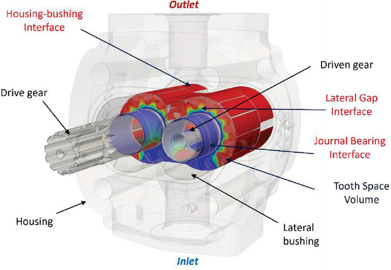
Figure 1 Illustration of a typical pressure compensated EGP.
Over the past few decades, various simulation methodologies and models of varying complexity have been proposed, that aim to analyse the physical phenomena in one or more operating domains of an EGP as well as the interactions between them. Models to analyse of fluid displacing action of EGPs in the fluid domain can be classified into three main categories namely analytical models, lumped parameter models and computational fluid dynamics (CFD) models. Analytical models, similar to the work by Manring and Kasaragadda [3], Ivantysyn and Ivantysynova [4], provide a theoretical description of fluid flow inside EGPs and can estimate the kinematic flow ripple using the geometrical information, but do not consider the effects of compressibility of the fluid. The lumped parameter models, such as the works by Vacca and Guidetti [5], Borghi et al. [6], divide the fluid domain into a number of control volumes, and solve mass conservation as well as fluid transport equations to determine the fluid flow and pressurization behavior inside the pump. Lumped parameter models are very powerful in simulation of EGPs as they are computationally inexpensive and can help estimating physical phenomena such as outlet pressure ripple, loads acting on the floating components due to fluid pressure, effects of cavitation and aeration etc. The estimation of loads on gears also allow coupling of the fluid domain pressures with the micromotion of gears which can affect the fluid domain predictions significantly. One of the major drawbacks of these models is that they significantly approximate the behavior of lubricating interfaces inside the pump and use analytical approximations as well as lubricating film gap assumptions while estimating the power losses arising from these interfaces. Therefore, when it comes to efficiency prediction, these models can not be considered most accurate. CFD models, as seen in the works of Castilla et al. [7], Frosina et al. [8], divide the fluid domain into infinitesimal meshes and solve the partial differential equations in a distributed mesh domain using numerical techniques and can accurately estimate the fluid flow and pressure behavior inside an EGP. These studies allow accurate estimation of phenomena such as cavitation and incomplete filling of the machine, local effects of fluid inertia as well as bubble collapse and damage at the cost of higher computational resources. Current works in literature using 3D CFD models also approximate the lubricating interface behavior as it becomes computationally expensive to add multiple mesh layers in the small lubricating film gap to obtain accurate estimation of power losses inside EGPs.
Accurate modeling of lubricating interface domain in EGPs is very important to accurately predict the power losses and estimate the energy efficiency of the pump. The behavior of the lubricating interfaces is significantly affected by the film gap height distribution which is a function of the motion and the deformation of the floating bodies forming these interfaces and thus is highly coupled with the solid body domain behavior of the pump. Different simulation models in literature use different assumptions while analysing the behavior of various lubricating interfaces in EGPs. Taking an example of lateral gap lubricating interface in EGPs, studies such as the ones by Borghi et al. [9] assume a predefined gap height distribution to determine the film pressure distribution from solution of Reynolds equation. Dhar and Vacca [10] showed the effect of coupling the axial motion of the lateral bushing on the lateral film behavior assuming that the lateral bushing is always under the state of force balance. The same authors (Dhar and Vacca [11]) extended the model to include the effects of pressure and thermal deformation of lateral bushing in the lateral gap interface analysis. Thiagarajan and Vacca [12] extended this work to include the mixed lubrication regime modeling and effect of surface roughness on the lateral lubricating film power losses. Thus, it can be seen that there can be increasing amount of complexity while modelling various of physical phenomena that can affect the lateral gap behavior in EGPs.
A recent work from authors’ research team by Ransegnola et al. [13] proposes a multi-domain simulation tool for external gear machine simulation called Multics-HYGESim. This simulation tool allows simultaneous/coupled analysis of different domains of EGP. The current study aims to leverage the capabilities of Multics-HYGESim to analyse effects of different physical aspects associated with the operation of an EGP in terms of simulations. Simulation options of Multics-HYGESim allows changing the complexity of assumptions taken to carry out the analysis of the pump on various levels. For example, the model can analyse only the fluid domain along with consideration of gear micromotion, whilst simplifying the lubricating domain with analytical solutions of the journal bearing and using a constant gap height laminar equation to model lateral gap interface. While, the most physically and computationally complex simulation possible involves consideration of lubricating interfaces using solution of the Reynolds equation for pressure evaluation, energy equation for thermal analysis, along with effects of linear and tilting motions of gears and bushings, temperature prediction of gears, bushings and the housing as well as pressure and thermal deformation of these bodies. Using this flexibility of the simulation tool, five simulation cases with increasing complexity will be considered. The overall behavior of the reference pump will be compared across these five cases in terms of various parameters that are important for the EGP designers and manufacturers to prototype new high performing units. These parameters include comparison of differences in housing wear, overall TSV pressurization, outlet flow/pressure ripple, volumetric and frictional losses from lubricating interfaces across four cases. Based on the comparison, the authors aim to establish a correlation between the effects of motion, deformation and thermal behavior of different bodies on the performance characteristics of the machine. Finally, the results from the simulation tool in all five cases will be compared with experimental data of volumetric and hydromechanical efficiency, outlet pressure ripple and housing wear to understand the importance of consideration different physical effects during simulation, on the EGP performance prediction.
The remaining part of the paper is divided into three sections. Section 2, describes the simulation tool and the details of analysis of different domains in brief, followed by description of cases considered along with the underlined assumptions and level of complexity of physical effects that are evaluated during simulation. Section 3 describes the simulation operating conditions and gives detailed comparison of reference machine performance parameters and provides insights into correlation of physical aspects considered in simulation with the results. Section 4 talks about important conclusions and provides recommendations regarding physical aspects to consider during simulation to predict the different components of the EGP performance.
2 Methodology
2.1 Multics HYGESim Overview
Figure 2 shows the schematic of different solvers of the simulation tool and the domains of the machine they model.
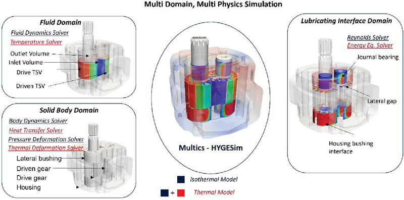
Figure 2 Different solvers in Multics-HYGESim simulation tool.
2.2 Fluid Domain Modeling
The evaluation of fluid dynamic behavior takes place using the fluid dynamic solver where the pump domain is divided into multiple control volumes or tooth space volumes. Using a lumped parameter approach, thermal pressure build-up equation (Equation (1)) and lumped temperature evaluation equation (Equation (2)) are solved for each control volume to predict the pressurization and thermal evaluation inside the pump. The flow between the control volumes through various geometrical connections such as the ones due to grooves on the bushings is modelled using orifice equation (Equation (3)). Along with mass transfer, enthalpy transfer and heat loss at orifices are estimated and considered in lumped parameter thermal modeling. The fluid dynamic solver also models the leakages at the gear tip – housing interface using a Couette-Poiseuille equation (Equation (4)). A geometrical pre-processor is run to determine the variation of TSV volume, the time derivative of TSV volume, connection areas and diameters between different control volumes, and other geometrical parameters required by the simulation model as a function of rotation angle of the shaft gear. More details regarding the approach can be found in [5, 13, 14].
| (1) | |
| (2) | |
| (3) | |
| (4) |
2.3 Lubricating Interface Domain
2.3.1 Reynolds Solver
The behavior of lubricating films at journal bearing, lateral gap and casing-bushing interface is modeled by the Reynolds solver, which solves the universal mixed thermal reynolds equation (Equation (2.3.1)), which was proposed by Ransegnola et al. [13] initially to include effects of cavitation by solving the distribution of density. This equation was modified as proposed by Mukherjee et al. [18] to include effects of thermal expansion of lubricant pressure. To estimate the contact forces based on the roughness profile of the bodies, an approach proposed by Lee and Ren [14] is used which relates the gap height information of the film to the contact pressure in the regime of asperity contact. The mixed lubrication modelling allows evaluation of viscous as well as asperity friction (Equation (2.3.1)) and accurate evaluation of power losses from the lubricating interfaces. To evaluate the meshing losses, a curve-fit relation proposed by Manne et al. [15] is used, to obtain which the authors simulated the EHL contact considering mixed lubrication effects.
| (5) | ||
| (6) |
2.3.2 Energy Equation Solver
In lubricating interface domain, the temperature distribution is governed by the solution of energy equation (Equation (7)).
| (7) |
The Equation (7) is three dimensional in nature and it accounts for effects of heat capacity of the fluid, energy convection, diffusion and dissipation. To reduce computational cost, Mukherjee et al. [18] proposed approximation of the Equation (7) using a polynomial approximation along the direction of film thickness, which reduces computational cost by converting Equation (7) in to a 2-dimensional equation. The heat dissipation denoted by arises due to viscous and asperity contact friction losses as shown in Equation (8).
| (8) |
2.4 Solid Domain
The solid domain modelling includes the body dynamics solver, pressure deformation solver, steady state heat transfer solver and thermal deformation solver. Body dynamics solver computes the linear and angular rigid body motion of floating bodies, i.e. the gears and the lateral bushings, by solving Newton’s second law. The loads acting on bodies from TSV pressures, lubricating interfaces, contact forces as well as frictional forces are considered while evaluating the motion of the bodies. The pressure deformation solver uses the influence matrix approach, which is based on finite element analysis under reference loads and scaling the obtained deformation based on actual loads as described in [10, 13], to determine the elastic deformation of the gears, bushings as well as the housing. The housing deformation modeling requires accurate constraints as described in [14]. As shown in figure, the housing body surface closer to the mounting plate side is more fixed and therefore planar X and Y degrees of freedom are fixed on the front side surface. The surface closer to the rear side plate is free and therefore only axial Z degree of freedom is fixed. Additionally, planar (X-Y) degrees of freedom are constrained in the locations where rigid locating pins are present.

Figure 3 Housing FEM boundary conditions for deformation calculation [14].
The temperature distribution of solid bodies including gears, lateral bushings and the housing during operation of an EGM is determined by the heat transfer solver. In the current work, a solution of 3-dimensional steady state conduction equation (Equation (9)) is used to estimate the temperature in solid body domain. As discussed by Mukherjee et al. [18], the thermal transience of solid components is a slow process physically due high heat capacity. Modeling the thermal transience would require simulating the EGM operation over hundreds of revolutions, which would be computationally expensive. Therefore, steady state heat transfer equation is used for temperature estimation. Equation (9), is solved using Finite Element Method (FEM) on a linear tetrahedral mesh, at certain characteristic time periods (e.g. every revolution of the EGM). The temperature of solid components is then determined using (Equation (10)), where Ti and Ti1 correspond to the current and previous solid body temperature, corresponds to the current solution of the steady-state heat transfer equation and is a relaxation factor less than 1. Appropriate boundary conditions are assigned in terms of Dirichlet, Neumann and mixed boundary conditions. Lubricating interfaces provide important boundary conditions to the solid body heat transfer. The power loss in lubricating interfaces is supplied as a neumann boundary condition to solid bodies forming the interface by equally distributing the heat. Additionally, heat is conducted between solid bodies through lubricating interfaces. This strongly coupled heat transfer system of equations for two or more bodies, connected via one or more lubricating interfaces is solved using the approach proposed by Mukherjee et al. [18].
| (9) | |
| (10) |
The temperature rise due to power losses inside an EGM causes thermal deformation of solid components. This thermal warping can significantly affect the gap height distribution in lubricating interfaces in PDMs leading to Thermo Elasto Hydrodynamic Lubrication (TEHL) effects. The thermal deformation is modeled by estimating the thermal strain using the steady state solid temperature distribution evaluated by the heat transfer solver and relating it to thermal stress and body deformation as indicated by Equations (11) to (14). Similar to pressure deformation, for thermal deformation estimation of gears and lateral bushings, inertia relief constraint [14] is used, while for housing, constraints are shown in Figure 3.
| (11) | |
| (12) | |
| (13) | |
| (14) |
The next section describes the simulation cases that are considered for the purpose of this study and the assumptions as well as physical phenomena considered for each case and the method of evaluation. It will also try to provide reasoning behind choosing these particular cases.
2.5 Simulation Cases Analysed
Figure 4 gives an overview of the simulation cases considered for the proposed study. For each case, the reference EGP will be simulated at corner operating conditions encompassing the overall operating region of the machine.
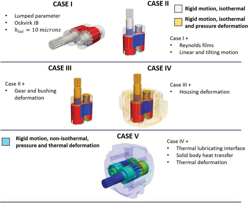
Figure 4 Overview of simulation cases considered.
2.5.1 Case I: Isothermal lumped parameter simulation with analytical films
This case considers only the evaluation of fluid domain with rigid body micromotion of gears. The assumptions under this case indicate simulation framework used for multiple previous studies in analysis of EGMs using lumped parameter models [5, 6], which has been shown to predict the performance behaviour of the machine including the hydromechanical [16] and volumetric efficiency, housing wear [5] etc. As the simulation framework in this case uses only 0D equations, the analysis is computationally inexpensive and can be used for quick performance prediction of the machine with considerable accuracy and therefore is considered as one of the cases analysed in this study.
2.5.2 Case II: Isothermal rigid simulation considering lubricating domain
This case considers Reynolds films to model the film behavior at journal bearing, lateral gap and housing bushing interface. The simulation can estimate linear and tilting motion of the lateral bushing in addition to the motion of gears due to accurate pressure force and moment evaluations from the lubricating interfaces. This simulation case does not consider deformation effects, but can allow comparison with case I, with more accurate consideration of leakages and viscous losses, especially from the lateral gap interface without assumption of any rigid gap height. One of the advantages of this case is accurate estimation of forces and moments on the lateral bushing from the gear side, allowing accurate design of balancing features.
2.5.3 Case III: Isothermal simulation considering deformation of gears and bushings
This case estimates the pressure deformation of gears and lateral bushings and their effects on the lubricating interface behavior. Consideration of deformation of these bodies allow accurate estimation of the power losses from journal bearing and lateral gap interfaces as it does not involve any assumptions pertaining to lubricating film behavior except consideration of symmetric behavior of top side and bottom side films. This framework has been used previously by Pawar et al. [20] to show prediction of EGM hydromechanical efficiency. The authors concluded that there is an overprediction of losses arising from lateral gap lubricating interface under the isothermal assumptions.
2.5.4 Case IV: Isothermal simulation considering deformation of gears, bushings and housing
In addition to gears and bushings, this case estimates the pressure deformation of the housing body of the machine. Brinkmann [17] et al. presented effects of housing deformation on the lateral lubricating interfaces of the machine. Pawar et al. [14] showed that it is possible to predict housing wear distribution accurately considering effects of housing deformation. In the current study, this case aims to analyse the effect of housing deformation on other pump performance parameters such as frictional losses and leakages at lubricating interfaces. Compared to case III, this case removes the symmetric assumption of top and bottom side films, and simulates all 12 lubricating interfaces providing the complete picture of EGP operating under isothermal conditions, but results in the more computationally expensive simulation.
2.5.5 Case V: Thermal Simulation considering pressure and thermal deformation of gears, bushings and housing
In this case, thermal effects in fluid domain, solid domain and lubricating interface domain are considered along with body deformation effects in a coupled manner. As indicated by Mukherjee et al. [19] for the case of axial piston machines, inclusion of thermal effects is essential for accurate evaluation of power losses in positive displacement machines. For the case of EGMs, thermal analysis can be important for accurate power loss estimation from journal bearing and lateral gap interface. The gap height at lubricating interfaces is strongly influenced by the pressure deformation which affects the power loss prediction. Inclusion of thermal analysis allows consideration of accurate fluid properties as well as determination of the gap height distribution after calculation of thermal warping of bodies. Appropriate boundary conditions are assigned to different locations of solid components. The lubricating interfaces serve as important power loss locations (Neumann boundaries) and conduction areas between solid components. The internal surfaces exposed to fluid chambers and external surfaces exposed to atmosphere are subjected to mixed boundary conditions. Compared to case IV, this case removes the assumptions of isothermal analysis. Along with temperature evaluation, thermal deformation of solid components is also evaluated in this case resulting in the most computationally expensive simulation. Illustration of boundary conditions applied to different surfaces of EGM housing is shown in Figure 5. Similar considerations are taken for the gears and lateral bushings.

Figure 5 Illustration of film and mixed boundary conditions for housing temperature evaluation.
3 Results and Discussion
The reference unit, PHP20QW20.20 is simulated at 5 different operating conditions encompassing the operating speed range of 500 to 2500 RPM and operating pressure range of 50 to 250 bar. ISOVG-46 is considered as the operating fluid while the temperature is assumed constant at 50C. Nominal dimensions of the unit are considered for simulation. Table 1 presents the EGP parameters, while Table 2 shows the details of operating conditions considered.
Table 1 Parameters of the reference EGP
| EGP Parameters | Value |
| Displacement | 22.38 cc/rev |
| Type | Spur involute |
| Maximum operating speed | 3500 RPM |
| Maximum operating pressure | 250 bar, 300 bar (intermittent) |
| Gear material | Steel |
| Bushing material | Aluminum |
| Housing material | Cast iron |
| Terminology | Operating Speed and Pressure |
| Low Speed Low Pressure (LSLP) | 500 RPM, 50 bar |
| Low Speed High Pressure (LSHP) | 500 RPM, 250 bar |
| Medium Speed Medium Pressure (MSMP) | 1500 RPM, 150 bar |
| High Speed Low Pressure (HSLP) | 2500 RPM, 50 bar |
| High Speed Low Pressure (HSHP) | 2500 RPM, 250 bar |
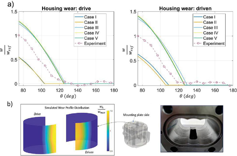
Figure 6 (a) Comparison of housing wear for all cases (b) 3D worn region prediction from case 4.
3.1 Housing wear-in and fluid dynamic comparison
Figure 6a indicates the housing wear predicted by the simulation model and comparison with experimentally measured wear profile. Consideration of pressure deformation is important as seen from case III and case IV results to predict the amount of wear on the housing surface. Case IV considers deformation of internal housing surface while determining the wear, allowing estimation of worn region at different axial sections as shown in Figure 6b, leading to a better prediction of the trend of housing wear with angle. Both cases III and IV overestimate the wear, though the magnitude of the wear lies within manufacturing tolerance region. Case V shows that thermal deformation effects are not very significant in affecting the magnitude of housing wear. The overprediction of the wear by cases III to V indicate non-linear deformation effects can exist at journal bearing liner as well as at the bushing surface which is in the contact with the housing, while the current model assumptions only consider linear deformation effects.
The housing wear profiles obtained from simulation are given as input to the model for corresponding cases. Figure 7 shows comparison of TSV pressurization at HSHP operating condition. Clearly, cases I & II, and cases III to V show very similar fluid dynamic behavior. The positions of the gears inside the housing affect the fluid dynamic behavior significantly. Due to deformations of the bushings and the housing, the gears in cases III to V are pushed towards the suction side by a larger magnitude. Additionally, the deformations of bodies negate the journal bearing effect seen in cases I and II at high speed which tends to increase the minimum gap at the journal bearings leading to an inefficient sealing at tip-housing interface. Therefore, cases I and II show early TSV pressurization from tip leakages, while cases III to V show TSV pressurization when the chamber is exposed to backflow groove.

Figure 7 TSV pressure comparison.
Figure 8 shows pressure ripple of comparison for all cases. The dual flank behavior of the reference pump can be accurately predicted by the simulation model. The pressure ripple behavior is not affected by deformation effects and all cases can predict pressure ripple accurately. Therefore, only lumped parameter assumptions are sufficient for estimating the pressure ripple of a pump accurately.
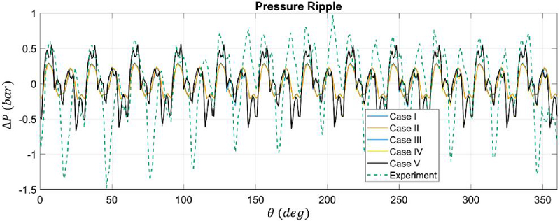
Figure 8 Pressure ripple comparison.
3.2 Frictional Torque Loss and Leakage Prediction
Figure 9 indicates distribution of torque loss predicted from different lubricating interfaces of the EGP at HSHP operation by the simulation model. Case I only involves lumped assumptions and can estimate the tooth tip as well as meshing losses accurately but fails to estimate losses at JB and LG interfaces due to not capturing the mixed lubrication effects and assumptions of constant gap height at LG interfaces. Case II slightly underestimates the JB losses as compared to cases III and IV indicating mixed lubrication effects are more important in JB loss prediction as compared to deformation. Case IV can capture the losses arising from both top and bottom side films including the effects of tilting of the gear and predicts slightly higher JB loss compared to case III indicating importance of considering the asymmetric effects at this interface. Case V considers temperature rise due to power losses in JB interfaces. The temperature rise causes viscosity of the oil in JB films to reduce which results in reduction of load carrying capacity of the JB and increase in mixed lubrication effects. Due to this reason case V predicts maximum frictional loss from JB interfaces.
Cases II and III overestimate frictional torque losses from LG interfaces. Case II, as indicated in Figure 10, predicts a uniform low gap height distribution, which results in higher friction. Case III, predicts regions of low gap height and asperity contact towards inlet section as indicated by Figure 10. The asperity contact friction and symmetric gap height assumption results in higher frictional torque prediction in case III. Case IV removes the symmetric assumption and estimates a lower value of frictional torque from LG interface. Thermal effects are essential to be considered for accurate power loss evaluation. The temperature rise in LG interface results in reduction of viscosity and predicted friction for case V.
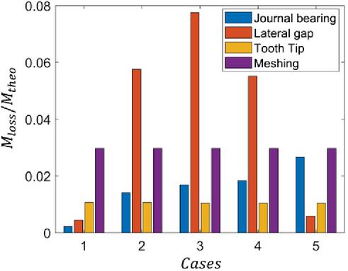
Figure 9 Comparison of torque loss in lubricating interfaces.
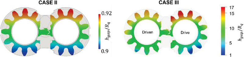
Figure 10 Comparison of lateral gap height for cases II and III.
Figure 11 presents comparison of leakages predicted by the simulation model for all cases at LSHP operating condition.
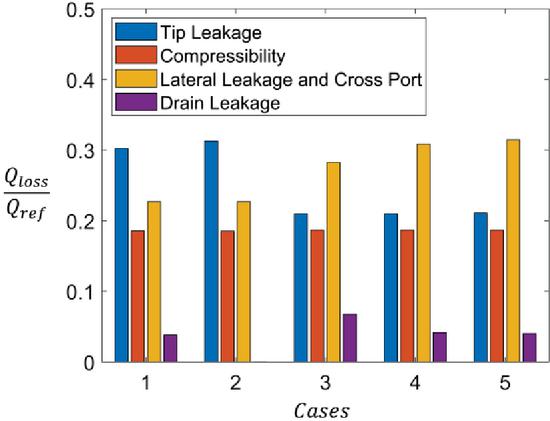
Figure 11 Comparison leakages in EGMs.
Volumetric losses arise mainly due to tooth tip leakages, compressibility losses and cross port as well as lateral gap losses. Tooth tip leakages mainly occur at the tooth tip interface closest to the suction volume and are dependent at gap height at these interfaces. Cases III to V consider deformation effects of bodies and predict higher sealing at tooth tip leakage interface resulting in slightly lower prediction of magnitude of this component compared to cases I and II. Compressibility losses are outlet pressure dependent and are similar for all cases. Lateral leakages are higher for cases III and IV due to higher gap height distribution at lateral gap interface compared to cases I and II. Case V shows maximum lateral gap loss due to lower viscosity of the oil at higher temperature.
3.3 Efficiency Comparison
Figure 12 shows the comparison of volumetric efficiency by all simulation cases with experimental values.
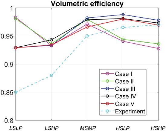
Figure 12 Comparison of EGP volumetric efficiencies predicted by simulation model with experiments for each case.
Cases I and II overpredict the efficiency at lower speeds and underpredict the efficiency at higher speeds. One of the reasons for underpredicted efficiency by these cases can be underprediction of tooth tip losses due to lower movement of gears towards the inlet. Cases I and II also underpredict drain leakages due to constant gap height assumption for case I and no deformation considerations for case II. Consideration of deformations of all bodies along with thermal effects can predict the volumetric efficiency trends as well as magnitudes with case V being the most accurate, which indicates the benefit of considering thermal effects. But the percentage improvement in prediction with respect to cases considering deformation effects is in the range of 0 to 1.5% in terms of volumetric efficiency, which can translate to more than 50% change in leakage prediction. This error in leakage prediction is highest when no deformation effects are considered as in cases 1 and 2. Therefore, it can be said that consideration of thermal effects, even though it shows marginal improvements in volumetric efficiency, can be important towards accurately estimating the leakages and the overall volumetric losses in the EGM.
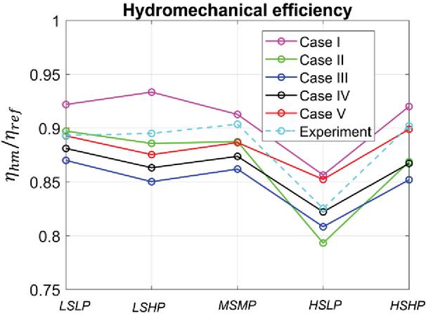
Figure 13 Comparison of EGP hydromechanical efficiencies predicted by simulation model with experiments for each case.
Figure 13 indicates comparison of hydromechanical efficiency for all cases with experimental values. Lumped parameter model underpredicts the frictional losses and overpredicts hydromechanical efficiency. At most operating conditions except LPHS, the case 5 can predict the hydromechanical efficiency with good accuracy compared to other cases. But consideration of thermal effects is seen to increase error in the efficiency prediction at LPHS case, which can be because other effects such as losses from seal as well as churning loss effects can be significant at LPHS are not considered in the model. Case 2 shows good efficiency match too, but the important physical effects are not accounted. Therefore, the frictional loss is not consistently predicted by this case across all operating conditions. Only consideration of deformation effects as shown from the Figure 14 below, overpredicts the frictional loss at most operating conditions, thus showing importance of including thermal effects.
For all simulation cases, the dimensions of the components were evaluated from drawings of the reference machine. The effect of tolerances on clearances between components was neglected. This can result in errors pertaining to estimation of wear for cases. A future consideration regarding evaluation of dimensions of the manufactured machine will be considered for model validation. The value of clearance considered also affect the power loss evaluation from lubricating interfaces thus adding a possible error source in the presented results. The heat transfer coefficient considered in the thermal simulation was estimated using a CFD analysis. A further study by the authors will validate the temperature prediction of solid components which will increase the confidence in the results of power loss presented by the thermal simulation. Additional errors might come due to ignoring effects of churning losses, losses arising from shaft seals etc. in the simulation results. As these effects are much smaller in magnitudes, they can be neglected in power loss estimations.
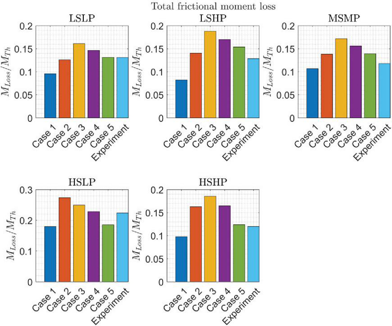
Figure 14 Comparison of EGP frictional losses normalized with theoretical torque predicted by simulation model with experiments for each case.
The comparison of simulation time taken for each case is indicated below in Table 3 to highlight the computational differences in all simulation cases.
Table 3 Simulation time comparison
| Cases | Average Time (For 2 Revolution) |
| Case I: Isothermal lumped parameter simulation with analytical films | 5–10 mins |
| Case II: Isothermal rigid simulation considering lubricating domain | 3–4 hours |
| Case III: Isothermal simulation considering deformation of gears and bushings | 1–1.5 days |
| Case IV: Isothermal simulation considering deformation of gears, bushings and housing | 2–3 days |
| Case V: Thermal Simulation considering pressure and thermal deformation of gears, bushings and housing | 4–5 days |
4 Conclusion and Outlook
Current study presents the comparison of different simulation model assumptions on the EGP performance and focuses on the effects of deformations of the gears, bushings and the housing as well effects of thermal considerations on pump fluid dynamic as well as friction loss, leakage and efficiency behavior. Five cases with increasing simulation complexity are considered and a comparison with experimental data is provided. Deformations of journal bearings, bushings and the housing lead to higher penetration of gear tips into the housing surface leading to a higher magnitude of housing wear. Consideration of housing deformation, as in case IV, can predict the axial trends in housing wear prediction. Thermal effects do not affect the wear prediction considerably.
TSV pressurization is affected by consideration of deformation effects as the gear positions vary in each case. The pressure ripple can be predicted accurately by all cases indicating deformation effects don’t influence simulated pressure ripple. To accurately predict the frictional torque loss and leakages, it is important to consider asymmetrical effects, deformation of gears and lateral bushings as well as thermal effects in lubricating interfaces. Case V therefore is the most complete simulation setup for efficiency analysis. Additionally thermal effect consideration can allow prediction of temperatures of solid bodies and lubricating interfaces, which can further detect possible thermal issues in the EGM design which were not seen for the reference machine. Cases III and IV can also predict volumetric and hydromechanical efficiency with fair accuracy at most operating conditions. These cases are important towards analysis of lubricating interfaces in terms of evaluation of gap height distribution and possibility of wear.
Nomenclature
| Pressure of TSV | |
| t | Time |
| Isothermal bulk modulus of fluid | |
| Volume of TSV | |
| Flow entering/exiting TSV | |
| Flow through flow connections between and TSV | |
| Flow coefficient of the orifice | |
| Area of the orifice | |
| Density of the fluid | |
| Viscosity of the fluid | |
| L | Width of the tooth tip |
| Tooth tip velocity at tooth separating and TSV | |
| Flow factors for mixed lubrication modeling | |
| h | Gap height at lubricating interface |
| Velocities of surfaces bounding the lubricating interface | |
| Temperature | |
| Heat capacity of the fluid | |
| Conductivity of the fluid | |
| Power loss per unit value in lubricating films | |
| Stress in solid components |
References
[1] Ivantysyn, J., and Ivantysynova, M., 2003, “Hydrostatic pumps and motors”. New Dehli, India: Tech Books Int.
[2] Zappaterra F., Vacca A., Sudhoff S.D., “A Compact Design for an Electric Driven Hydraulic Gear Machine Capable of Multiple Quadrant Operation,” Mechanism and Machine Theory, 177, 10504, 2022.
[3] Stryczek J, Fundamentals of designing hydraulic gear machines, PWN, 2021.
[4] Manring, N., D., and Kasaragadda, S., B. 2003, “The Theoretical Flow Ripple of an External Gear Pump,” Journal of Dynamic Systems, Measurement, and Control, vol. 125, no. 3, p. 396.
[5] Vacca, A., Guidetti, M., 2011, “Modelling and Experimental Validation of External Spur Gear Machines for Fluid Power Applications,” Elsevier Simulation Modelling Practice and Theory, 19 (2011) 2007–2031.
[6] Borghi, M., Zardin, B., Specchia, E. 2009, “External Gear Pump Volumetric Efficiency: Numerical and Experimental Analysis”, SAE Technical Papers, doi: 10. 4271/2009-01-2844.
[7] Castilla, R., Gamez-Montero, P-J., Ertrk, N., Vernet, A., Coussirat, M., Codina, E., 2010, “Numerical simulation of turbulent flow in the suction chamber of a gearpump using deforming mesh and mesh replacement”, Int. J. Mech. Sci. 52(10), 1334–1342.
[8] Frosina, E., Senatore, A., Rigosi, M., 2017, “Study of a high-pressure external gear pump with a computational fluid dynamic modeling approach”, Energies 10(8), 1113.
[9] Borghi, M, and Zardin, B. “Axial Balance of External Gear Pumps and Motors: Modelling and Discussing the Influence of Elastohydrodynamic Lubrication in the Axial Gap.” Proceedings of the ASME 2015 International Mechanical Engineering Congress and Exposition. Volume 15: Advances in Multidisciplinary Engineering. Houston, Texas, USA. November 13–19, 2015.
[10] Dhar S., Vacca A., A novel CFD – Axial motion coupled model for the axial balance of lateral bushings in external gear machines, Simulation Modelling Practice and Theory, Volume 26, 2012, Pages 60–76, ISSN 1569-190X.
[11] Dhar S., Vacca A., A novel FSI–thermal coupled TEHD model and experimental validation through indirect film thickness measurements for the lubricating interface in external gear machines, Tribology International, Volume 82, Part A, 2015, Pages 162–175.
[12] Thiagarajan, D., Vacca, A., 2017, “Mixed Lubrication Effects in the Lateral Lubricating Interfaces of External Gear Machines: Modelling and Experimental Validation,” Energies, 10(1), 111.
[13] Ransegnola, T., Zappaterra, F., Vacca, A., 2022, “A Strongly Coupled Simulation Model for External Gear Machines Considering Fluid-Structure Induced Cavitation and Mixed Lubrication,” Applied Mathematical Modelling, 104, 721–749.
[14] Pawar A., Vacca A., and Rigosi M., “Prediction of housing wear-in in external gear machines considering deformation effects, ASME Symposium of Fluid Power and Motion Control, 2023.
[15] Manne VHB, Vacca A. And Singh K., 2023 A Curve-fit Traction Coefficient Relation of Mixed EHL Line Contact with Hydraulic Fluid and Steel Surfaces, Tribology Transactions, 66:2, 364–380.
[16] Rituraj R., Vacca A., Rigosi M., Modeling and validation of hydro-mechanical losses in pressure compensated external gear machines, Mechanism and Machine Theory, Volume 161, 2021.
[17] L. Brinkmann, S. Kock, J. Lang, and G. Knoll, “Tribological analysis of the plain bearings in an external gear pump,” in IOP Conference Series: Materials Science and Engineering, IOP Publishing, vol. 1097, 2021, p. 012–014.
[18] S. Mukherjee, A. Vacca, L. Shang, and A. Sharma, “A thermal modeling approach for the piston/cylinder interface of an axial piston machine under asperity contact,” Meccanica, vol. 58, no. 10, pp. 1929–1957, 2023.
[19] S. Mukherjee, L. Shang and A. Vacca, “Numerical analysis and experimental validation of the coupled thermal effects in swashplate type axial piston machines”, Mechanical Systems and Signal Processing, 2024.
[20] A. Pawar, VHB. Manne, A. Vacca, M. Rigosi, “Analysis of torque efficiency of External Gear Machines considering gear teeth roughness,” Mechanism and Machine Theory, 199, DOI: 10.1016/j.mechmachtheory.2024.105675.
Biographies

Ajinkya Pawar completed his bachelor’s degree in mechanical engineering and master’s degree in Robotics from Indian Institute of Technology Madras, in 2020. He started pursuing a doctorate degree in mechanical engineering at Purdue University under the guidance of Prof. Andrea Vacca. His interests are in numerical modeling of external gear machines considering deformation and thermal effects.

Andrea Vacca is the Maha Fluid Power Faculty Chair and a Professor at Purdue University. Dr. Vacca received his doctoral degree from the University of Florence (Italy) in 2005, and he joined Purdue University in 2010 after being an Assistant Professor at the University of Parma (Italy). Fluid power technology has been Dr. Vacca’s major research interest since 2002. Dr. Vacca authored the textbook “Hydraulic Fluid Power” by Wiley, more than 150 technical papers and 18 patents. In 2019 he received the J. Bramah medal from the U.K. Institution of Mechanical Engineers. He is a fellow of the American Society of Mechanical Engineers (ASME), and a former chair of the Fluid Power Systems and Technology Division (FPST) of ASME, and of the Fluid Power Division of the Society of Automotive Engineers (SAE). Dr. Vacca is also one of the Directors of the Global Fluid Power Society (GFPS).

Manuel Rigosi completed his MSc degree in Mechanical Engineering from the University of Parma, in 2011. After an internship, he joined Casappa R&D Department in the role of Simulation Engineer, focused in replicating the physical phenomena within hydraulic gear and piston pumps through the usage of customized lumped parameter models and 3D simulations. In 2018 he took the responsibility for the development of new products with a team of engineers and designers. In recent years he has contributed to innovation by signing 4 patents regarding solutions already applied to the latest products Casappa is offering on the market today.
International Journal of Fluid Power, Vol. 25_4, 465–492.
doi: 10.13052/ijfp1439-9776.2543
© 2024 River Publishers