Adaptive Meter-out Control of Pneumatic Drives by Using Novel Multi-stable Solenoids
Thomas Kramer* and Jürgen Weber
Chair of Fluid-Mechatronic Systems (Fluidtronics), Institute of Mechatronic Engineering, Technische Universität Dresden, Helmholtzstraße 7a, 01069 Dresden, Germany
E-mail: thomas.kramer@tu-dresden.de; juergen.weber@tu-dresden.de
*Corresponding Author
Received 10 October 2024; Accepted 30 October 2024
Abstract
Multi-stable solenoids are novel energy-efficient actuators, which combine the continuous adjustability of proportional solenoids with the energy efficiency of polarised magnetic circuits. They can hold any armature position without power supply. Thus, they are well suited for an automation of pneumatic throttle check valves, in order to set the throttle cross-section and thus the cylinder piston velocity to a specific value and hold it for a certain time. This is useful in the context of industry 4.0 to produce on demand with customised piston velocities or to gradually compensate for the increasing frictional forces during cylinder lifetime.
This paper deals with the application of novel multi-stable solenoids to actuate a throttle check valve for an adaptive meter-out control of pneumatic cylinder drives. Therefore, the design of a multi-stable solenoid for a given throttle valve is presented. The functionality of the combination is verified by measurements. The automated throttle is integrated in a simple pneumatic cylinder drive to investigate the adjustability of and disturbance influences to the piston velocity. On that basis, a feed forward and a closed loop control are presented for setting of specific piston velocities.
Keywords: multi-stable solenoid, solenoid, pneumatic, throttle check valve, automation, feed forward control, closed loop control.
1 Introduction
Electro-magneto-mechanical transducers are widely used in fluid power applications for actuating switching and proportional valves. These are often solenoids, which are based on the reluctance principle. For such solenoids, various design and operating principles have been established (e. g. [1]). They can be arranged concerning the output behaviour and the magnetic circuit design according to Table 1. Stable states mean here that no current is flowing.
Table 1 Classification of existing solenoid principles (state of the art: black, state of research: grey)
| switching (limited position number) | continuously abjustable (any position) | |
| neutral magnetic circuit | mono-stable switching solenoid | mono-stable proportional solenoid |
| polarised magnetic circuit | bi-stable, tri-stable, … switching solenoid | multi-stable solenoid |
Neutral magnetic circuits as mono-stable solenoids with their simple design are widely used. They consist of a coil, a yoke as fixed soft magnetic part and a movable soft magnetic armature, as seen in Figure 1 (left). The coil generates a magnetic field in the magnetic parts depending on the coil current . The resulting magnetic flux leads to a magnetic force , which acts on the armature. In combination with a spring, an armature position can be set according to the simplified force balance of spring force and magnetic force . A distinction is usually made between switching solenoids with a limited position number and proportional solenoids with continuous adjustability. Such neutral magnetic circuits require a continuous power supply to hold any position except for the stable one given by the spring force (maximum air gap ).
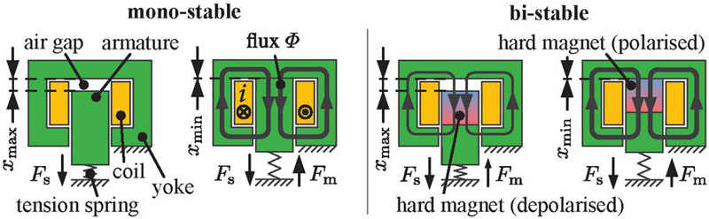
Figure 1 Exemplary designs of neutral mono-stable switching solenoid (left) and polarised bi-stable switching solenoid (right, remanence principle, based on [2]) with its switching positions.
Bi-stable solenoids [3, 4, 5] or solutions with more than two, but a limited number of stable switching positions [6, 7], are an energy-efficient alternative to neutral mono-stable switching solenoids. For this, different design principles are known [2, 3]. Figure 1 (right) illustrates a bi-stable design as example. Additional to the soft magnetic parts, they consist usually of a hard magnetic part. This leads to a magnetic flux even without exciting the coil. The magnetic circuit is polarised. Thus, two forces can be realised that remain without power supply: a spring force and a permanent magnetic force. These forces result in two stable armature positions and . The transition between the positions is realised by a short current pulse through the integrated coil. The existing solutions of polarised magnetic circuits aim only at a limited number of switching positions.
1.1 Multi-stable Solenoids
In order to combine both, the continuous adjustability of proportional solenoids and the energy efficiency of polarised magnetic circuits, multi-stable solenoids are currently a focus of research. Such solenoids can hold any armature position without power supply. Potential applications for this novel actuator type are varied. Especially in fluid power, they can be used for actuating any kind of proportional valves. For this purpose, [8] provides an approach and the demonstration of the fundamental behaviour for multi-stable solenoids. Besides, such solenoids are investigated for gravity compensation according to [9, 10, 11] as well.
The working principle is based on the utilisation of the inner magnetic hysteresis behaviour of semi-hard magnetic material. Such materials have a high energy storage capability and can be polarised by the solenoid’s integrated coil. Figure 2 illustrates the working principle with the material property of AlNiCo 9 and the basic design of multi-stable solenoids.
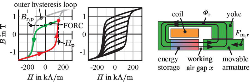
Figure 2 Magnetisation procedure for FORC generation (left), set of FORCs (middle), both for AlNiCo 9 from measurements using a self-made hysteresisgraph for hard magnetic materials (principle according to [12]), principal design of multi-stable solenoids (right).
The inner magnetic hysteresis behaviour can be accesses by so-called first order reversal curves (FORC). Therefore, the material is first magnetised along an outer hysteresis branch starting at saturation as reference (red line). After field reversal at any operating point , the associated FORC arises (green line). If the external field is shut down, the remanent flux density remains. Depending on the reversal point , any remanent point in the hysteresis loop can be reached as shown in Figure 2 (middle). Thus, the semi-hard magnetic material acts as variable magnetic energy storage.
The design of the proposed multi-stable solenoids is as simple as possible. The magnetic circuit consists of the energy storage, a yoke and an armature. The coil is in the center. With a current pulse through the coil, a magnetic field is generated in the energy storage for polarising it to a certain level. After shutting off the pulse, the remanent operating point according to the -behaviour is set. The remanent flux density leads to a remanent magnetic flux in the magnetic circuit and thus to a magnetic force acting on the armature. In combination with a spring, a remanent armature position results. Any armature position in the operating range can be set and hold without additional power supply, which corresponds to a multi-stable behaviour.
1.2 Automation of Pneumatic Throttle Check Valves
One potential application of such multi-stable solenoids in fluid power is the automation of pneumatic throttle check valves, in order to adjust the throttle opening automated during operation. This allows, for example, cylinder piston velocities to be set as required (industry 4.0: produce on demand) or to gradually compensate for increasing frictional forces during cylinder lifetime as a result of increasing seal wear.
Figure 3 illustrates a typical pneumatic cylinder drive with meter-out control. Meter-out throttling is usually used to set the cylinder piston velocity nearly independent from an external load force and from supply pressure . Furthermore, the stiffness of the mechanical system is increased.
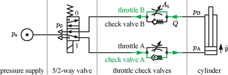
Figure 3 Pneumatic cylinder drive with meter-out control.
The metering is realised by two throttle check valves, one for each direction of movement. For example, for moving the cylinder piston out, the mass flow passes check valve A and throttle B, as illustrated in the schematic. By adjusting the throttle cross section , the volume flow rate and thus the piston velocity is set. This is currently done manually, usually once when the system is commissioned. An automation, for example with multi-stable solenoids would enable a variable setting of the piston velocity during operation. Fundamental investigations on such automation are presented in [13] and may be summarized as follows: Two types of throttle valves, a spool and a poppet type, have been designed and equipped with an existing demonstrator of a multi-stable solenoid. They were investigated concerning the adjustability of the cylinder piston velocity. The presented results illustrate that a combination of spool valve and multi-stable solenoid has to be preferred due to low disturbance forces of the spool valve. This is an important fact, because disturbance forces or generally unknown load forces affect the force balance on the armature and detune its remanent position according to
| (1) |
where denotes the spring stiffness and its preload.
Figure 4 (left) illustrates the spool valve design in principle (detailed in [13]). It has an operating range of . The corresponding transfer characteristics, the volume flow rate and the resulting force on the spool, can be seen in Figure 4 (right) [13]. It has to be taken into account that the force behaviour includes the spring, whose force can be assumed as constantly increasing with the armature position.
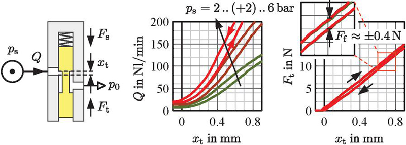
Figure 4 Principal design of spool valve (left), measured transfer characteristics of spool valve (right).
The flow rate behaviour depicts an expected adjustability of the volume flow rate depending on the throttle opening and supply pressure . The force behaviour illustrates the low disturbance influence with small hysteresis effects, mainly induced by friction forces . The curves are nearly independent from supply pressure . Due to its low disturbance influences, the spool valve serves as the basis for the continuing work in the present paper.
The focus of this paper is on the application of the automated throttle for a flexible setting of cylinder piston velocity during operation. Initially, the design of a specific multi-stable solenoid for the given spool valve is presented. It is verified by measurements of the remanent behaviour. In the next step, the combination of spool valve and multi-stable solenoid is analysed to demonstrate its suitability. The automated throttle is attached to a simple pneumatic cylinder drive as meter-out flow control, in order to investigate the nominal behaviour and disturbances. On that basis, a feed forward and a closed loop control are proposed and analysed, with which piston velocity settings can be realised.
2 Design of Multi-stable Solenoid for Driving Spool Valve
For designing multi-stable solenoids, an analytical design approach has been developed (basics in [8]). The approach is based on a reluctance model of energy storage as magnetic source and variable air gap as magnetic sink. Only the maximum actuator performance is taken into account. The energy storage is considered to be fully polarised and is therefore modelled with its outer hysteresis loop (see Figure 2 (left)). The approach calculates the magnetic circuit design for given specifications. The starting point is the mechanical requirement for the actuator. The coupling between magnetic and mechanical properties is based on the equality of the change of magnetic energy and the change of mechanical work. In order to validate the design approach, FE simulations are carried out and compared with the analytical solution.
2.1 Inputs of the Design Approach
Specifications for the design approach are the required mechanical work as nominal design operating point (maximum force at maximum air gap), a selected energy storage material with its outer hysteresis loop, a corresponding air gap design and power supply parameters.
The spool valve determines the operating point. For fully opening of the valve, a minimum stroke of is required. The nominal air gap is therefore set to . The low disturbance forces do not require a particular force level. A nominal force should be sufficient to ensure proper adjustability of the remanent position in combination with a spring.
For the energy storage material, AlNiCo 9 is selected. It is a semi-hard magnetic material with a high energy storage capability. With its approximately ideal flux source behaviour, a simple air gap can be used for reaching a nearly linear force behaviour (see [8]).
The coil is designed for a nominal (maximum) current at a maximum input voltage .
2.2 Outputs of the Design Approach
With these specifications, the magnetic circuit is dimensioned. This includes the calculation of energy storage size, coil size and parameters as well as resulting position-dependent remanent force behaviour. The developed design, relevant size parameters and the remanent force behaviour are depicted in Figure 5. It has to be taken into account that the energy storage is divided into two parts for reducing leakage fluxes.
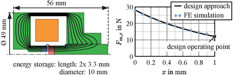
Figure 5 Design of multi-stable solenoid (FE model) with relevant size parameters (left), comparison of remanent force behaviour from analytical design approach and FE simulations (right).
2.3 Validation with FE Model
The magnetic circuit design is validated by static FE simulations. The FE model, as shown in Figure 5 (left), consists of the energy storage and soft magnetic material. The energy storage (blue and red part) is fully polarised according to the reluctance model by using the outer loop as material definition (see Figure 2 (left)). Soft magnetic material (green parts) is a machining steel 1.0715 and defined by its anhysteretic curve. Only the energy storage acts in the FE simulation as magnetic field source. The coil is not in use (). The simulation results are illustrated in Figure 5 (right) as blue dots. They show very good agreement and thus confirm the design based on the analytical approach.
The solenoid design is prepared for manufacturing and is built up. Figure 6 illustrates a photo and the detailed construction of it.
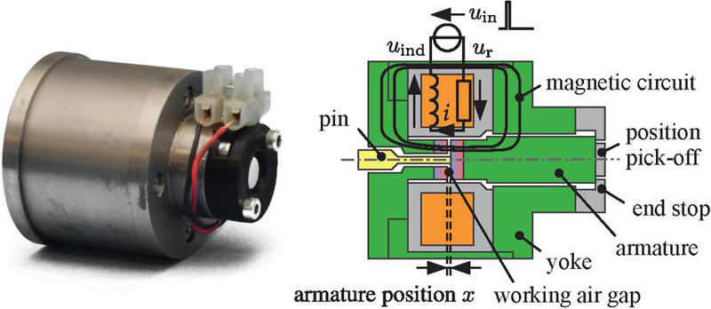
Figure 6 Photo of developed multi-stable solenoid (left) and its detailed construction in half-section (right).
2.4 Verification of Aimed Specification
The multi-stable force behaviour of the assembled solenoid is measured, in order to characterise its real potential and to verify the mechanical specification. Therefore, the test setup from Figure 7 is used.
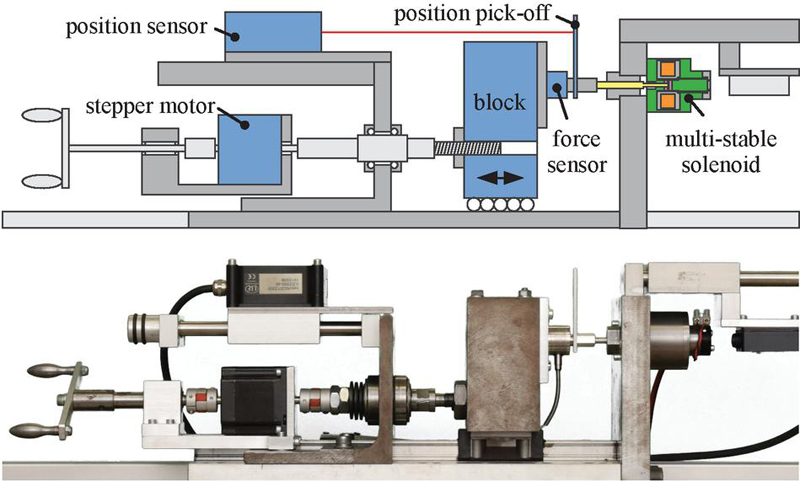
Figure 7 Measurement setup for characterising remanent force behaviour of multi-stable solenoid.
Measurements are done at fixed armature positions, which are adjusted by the movable block. At various positions, different polarisation states are set and the resulting magnetic force is determined with the force sensor. The measurements are fully automated by using the stepper motor for moving the block from position to position.
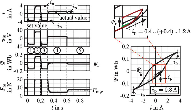
Figure 8 Polarisation procedure for setting remanent magnetic forces at fixed armature positions, time-dependent behaviour (left), electro-magnetic behaviour (right).
The polarisation is done with the illustrated procedure in Figure 8. In the first step, the semi-hard magnetic material is excited to negative saturation, in order to enable a reproduceable reference point (reset hysteresis history). Therefore, the coil current is regulated to . In the second and third step, the outer hysteresis loop is run through completely by exciting the coil to positive saturation and afterwards to again for investigation reasons of the flux linkage behaviour (see [8]). During the fourth step, the material is polarised to a defined level by regulating the current to (polarisation current). In the fifth, the final step, the power supply is switched off, the current decreases to zero and the remanent operating point sets in. The step times are chosen so that the steady states of current and magnetic force are reached at every operating point (). To gain knowledge of the electro-magnetic behaviour, the flux linkage (summed magnetic flux over all coil windings ) is calculated from input voltage and coil current according to the law of induction with
| (2) |
(see schematic in Figure 6 and also [8]). Figure 8 shows at the bottom right side the setting of remanent flux linkage in the electro-magnetic map . The magnetic flux leads directly to the remanent magnetic force . By varying the polarisation current , the remanent flux linkage and thus the remanent magnetic force can be set to any level in the operating range as depicted exemplary in Figure 8 (top right).
The measurements are done for various polarisation currents and armature positions. The resulting remanent force behaviour is illustrated in Figure 9.
The comparison of the measurements and FE simulations shows a good qualitative match. The deviations can be attributed to an inhomogeneous polarisation of the energy storage. Ideally, a pure axial polarisation is specified in the FE simulation. In reality, the coil does not achieve complete axial polarisation due to stray fluxes. This is probably due to the specific semi-hard magnetic material in combination with the compact design of this solenoid. Compared to AlNiCo 9, investigations on a demonstrator made of anisotropic CROVAC 12 shows a much better match between FE simulation and measurement (compare [8]).
With the help of a spring, the remanent forces are utilised to set remanent positions. Figure 9 (right) depicts the used spring characteristic to achieve the throttle’s operating range of . Remanent armature positions are given at the intersection of spring and remanent magnetic force characteristics (green dots).
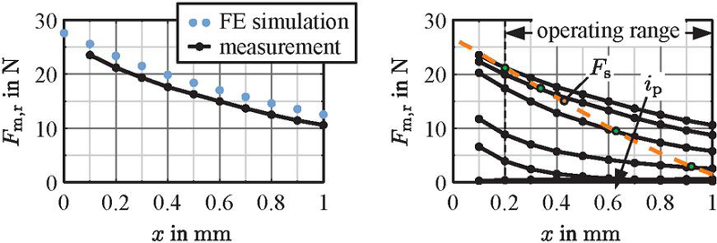
Figure 9 Comparison of measured remanent force behaviour and FE simulations at fully polarised energy storage (left), measured remanent force behaviour for variations of polarisation current with remanent operating points at force balance points (right).
3 Multi-stable Throttle Behaviour
The spool valve is equipped with the multi-stable solenoid, in order to proof the intended functionality of the combination. The focus is on setting remanent armature positions with corresponding flow rates in the working range of the spool valve. The measurement setup is illustrated in Figure 10.
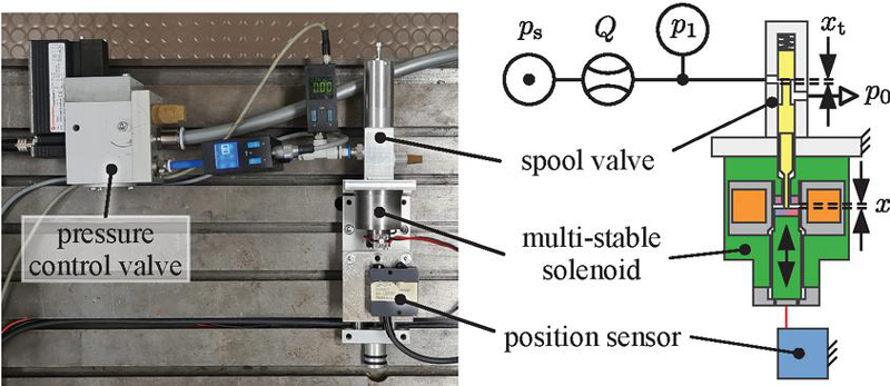
Figure 10 Measurement setup for characterising combination of throttle valve and multi-stable solenoid.
In addition to the automated throttle valve, it consists of a pressure control valve to set the supply pressure level and sensors for volume flow rate and pressure at the inlet of the valve. The solenoid is equipped with a position sensor at the backside to measure the armature position . It has to be taken into account that the throttle opening is inverse to the armature position according to with .
With this setup, measurements are done for various remanent operating points. They are set by using the polarisation procedure, which is exemplary illustrated in Figure 11 (left) (procedure from Figure 8 without outer loop).

Figure 11 Polarisation procedure for setting remanent armature positions with corresponding volume flow rate (left), multi-stable behaviour of armature position and volume flow rate (right).
After the polarisation, a remanent armature position sets in, which holds the throttle cross-section open at the corresponding level without additional power supply. Depending on the supply pressure , a volume flow rate is established. By varying the polarisation current , the armature position and thus the throttle opening can be set to any level in the operating range. Consequently, the volume flow rate can be adjusted. Figure 11 (right) depicts the setting of various armature positions and volume flow rates depending on the polarisation current .
The graphs and illustrate the fundamental operating principle. In nearly linear dependence on the polarisation current , armature position and thus volume flow rate can be set to any value. The intended operating range is covered in accordance with the requirements from the spool valve.
The addressed application raises the question of the long-term stability of the remanent state. According to [14], it can be assumed from the perspective of the magnetic material that the remanent operating point hardly changes at all. Nevertheless, the long-term stability should be the subject of further investigations.
4 Multi-stable Adjustment of Cylinder Piston Velocity
The automated throttle is integrated in a simple pneumatic cylinder drive, in order to investigate the transfer characteristic from polarisation current to resulting piston velocity. The measurement setup is illustrated in Figure 12.
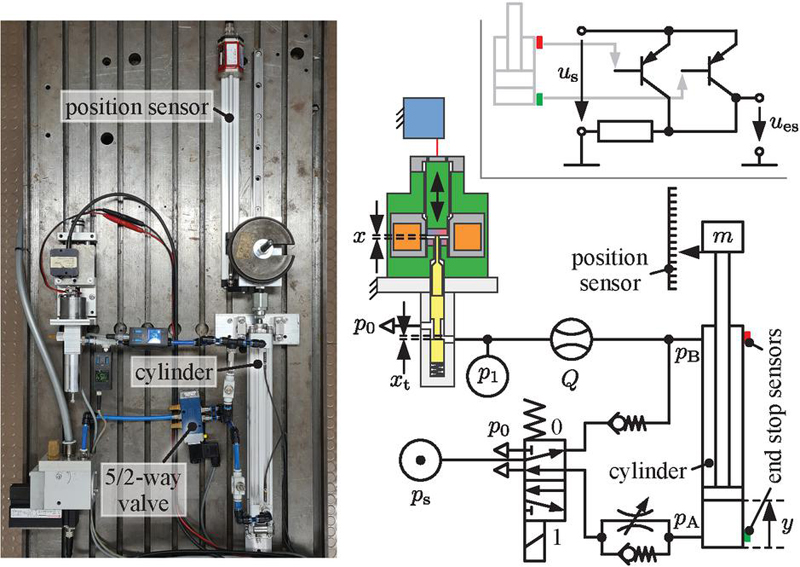
Figure 12 Measurement setup for characterising multi-stable adjustment of cylinder piston velocity.
The setup is based on a conventional meter-out control system as shown in Figure 3. The throttle check valve for moving out is closed and bypassed by the spool valve (closed throttle not shown in the figure). In order to measure the armature position, the solenoid is in this stage of development not sealed. But this does not disturb the measurements, since the meter-out control has here the advantage of an outlet to ambient. The end stops of the piston are determined by proximity sensors. Additionally, the piston position is continuously measured with a position sensor. The cylinder has a piston diameter and a stroke length . The moved mass is .
With this setup, the measurements are done. They are based on the procedure as illustrated in Figure 13.
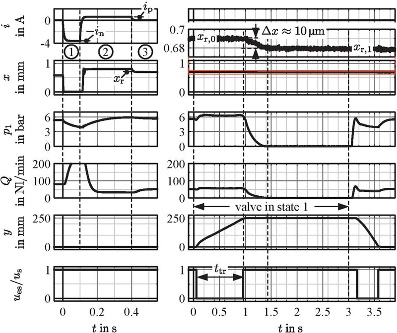
Figure 13 Procedure for setting defined cylinder piston velocity, polarisation procedure (left), cylinder piston movement (right).
Initially, the 5/2-way valve is in state 0 (move in). The multi-stable solenoid is polarised by the current according to the procedure in Figure 11, in order to set a specific throttle opening. After the polarisation, the valve is switched to state 1 for moving the piston out. After three seconds, the valve is reset to state 0 for reaching the start condition. During moving out, the piston velocity is determined in a practice-oriented manner by means of the end stop sensors. Therefore, the travel time between the end stops is measured. Due to limited measurement channels, a logical or-connection of both end stop sensors is used according to the circuit in Figure 12 (top right). If the piston is in one of the end stops, the signal is high, during travel low. The time between falling and rising edge is the travel time as marked in Figure 13. From this, the mean piston velocity is calculated by
| (3) |
4.1 Nominal Behaviour
On that basis, the nominal transfer characteristic is measured and investigated. Therefore, the supply pressure is set to nominal value and the described procedure is applied for various polarisation current . Figure 14 illustrates the resulting remanent armature position and the resulting piston velocity . The measurements are repeated five times for investigating reproducibility. The curves connect the average values of these five measurements. In the lower graphs, the corresponding error bars as relative deviation
| (4) |
and
| (5) |
are shown. The reference values and are here the mean value of all five measurements. The nominal piston velocity is set to the maximum value .
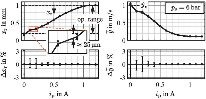
Figure 14 Nominal transfer behaviour of armature position (left) and cylinder piston velocity (right) with error bars for multiple measurements.
The results show a nearly linear adjustability of the piston velocity in a majority of the operating range according to the remanent position behaviour. Due to the valve’s flow rate behaviour (see Figure 4), the curve flattens out with small throttle openings. The lowest velocity is given by the leakage of the spool valve. The variation of the repeat measurements is small and only significant at small air gaps (low polarisation currents). In this area, the intersection angle between spring and remanent force characteristic is small (see Figure 9). This results in a high sensitivity to slightly varying force components (e. g. friction forces).
4.2 Disturbance Behaviour
In practice, varying boundary conditions occur and may influence the remanent operating point and consequently the piston velocity. The conditions include changes in the supply pressure, in load and friction forces as well as in temperature. Basically, meter-out control is inherently robust against load and pressure conditions. This can also be demonstrated here by applying different supply pressures and as an example, as shown in Figure 15.
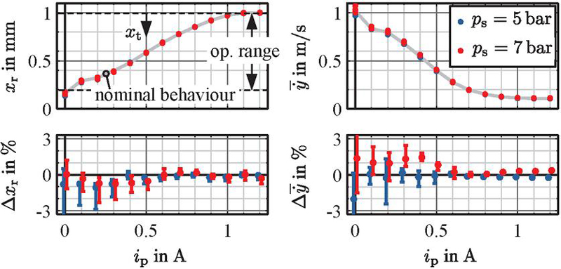
Figure 15 Disturbance behaviour of armature position (left) and cylinder piston velocity (right) for two different supply pressures with its error bars related to nominal behaviour.
Nevertheless, there are deviations from the nominal behaviour of up to in the operating range (without , references and are here the averaged nominal behaviour from Figure 14). The remanent armature position and thus the piston velocity is slightly influenced by supply pressure . This can be attributed to pressure-dependent flow effects and friction conditions at the spool (see also [13]).
In this context, investigations have shown that the armature shifts slightly after the piston is moved out (see close-up of in Figure 13). In this area, the pressure at the inlet of the spool valve drops to zero due to end of piston movement. This leads to changing pressure and thus force conditions at the spool resulting in a slight shift. In order to investigate the effect, the solenoid is polarised once and then multiple piston strokes are carried out sequentially. Figure 16 depicts the shift behaviour of the remanent armature position over the measurement regime and the corresponding piston velocity behaviour (references and are here the values of the first stroke ).
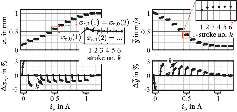
Figure 16 Settling behaviour of armature position (left) and cylinder piston velocity (right) for sequentially piston strokes after one polarisation.
The curves show the gradual displacement, in each case from the remanent position before to the remanent position after the piston movement (see also Figure 13). The armature shifts especially during the first stroke after polarisation. Afterwards, there is hardly any displacement. It seems that the varying pressure conditions have a corresponding force effect on the armature. The influence of this additional force probably results in different rest positions in the static friction range.
Since this shifting effect is reproducible, it can be considered in the velocity controller.
5 Adaptive Piston Velocity Setting
During operation, there is usually a requirement to set a certain piston velocity. If there are no special accuracy demands, a feed forward control based on the transfer behaviour can be used due to low disturbances. For higher accuracy requirements, a closed loop control can be set up that determines the piston velocity during operation and feeds it back to repolarise the multi-stable solenoid. Both control strategies are investigated.
5.1 Feed Forward Control
For the feed forward control, the transfer behaviour can be simply inverted to get the control law . This is illustrated in Figure 17. Here, an energy-optimised polarisation with shorter pulse times (required polarisation energy ) and a higher resolution with is used. The control law uses mean values over five measurements. It should be noted that velocities cannot be achieved here due to spool leakage.
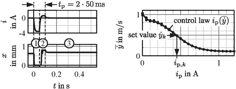
Figure 17 Energy-efficient polarisation procedure (left), nominal transfer behaviour of cylinder piston velocity as control law for feed forward control (right).
The control strategy is exemplary investigated on a setpoint profile at constant supply pressure and on a disturbance profile at constant velocity setting as depicted in Figure 18.
For every change in the setpoint, the solenoid is repolarised according to the control law (orange dots in the behaviour ). Afterwards, the piston moves out and in repeatedly without polarisations.
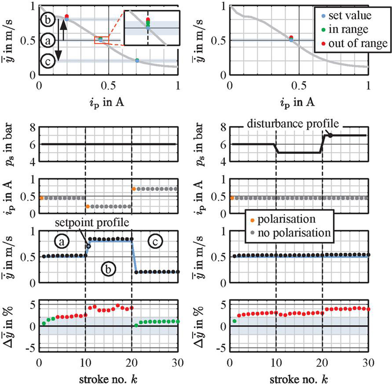
Figure 18 Behaviour of cylinder piston velocity for setpoint profile (left) and disturbance profile (right) by using feed forward control.
The resulting velocity behaviour illustrates a good agreement with deviation up to (reference is here the set value ). The observed disturbance behaviour is also reflected in the measurements. After the polarisations, there is a settling behaviour due to armature displacement. The deviations depend on the setpoint value, which can be attributed to different sensitivities in the working range (see crossing angle between spring and magnetic force characteristic in Figure 9 and error bars in Figure 14). In this context, it seems that the armature position and thus of the piston velocity depends also on the history and measuring conditions (setpoint profile . Supply pressure variations lead to slight deviations as seen in the results of the disturbance profile. These studies show that a feed forward control is basically sufficient for many applications, where deviations up to .. are acceptable.
5.2 Closed Loop Control
With a closed loop control, the accuracy can be improved. The approach is a purposeful repolarisation of the solenoid based on the actual determined piston velocity. The used control strategy is illustrated in Figure 19.
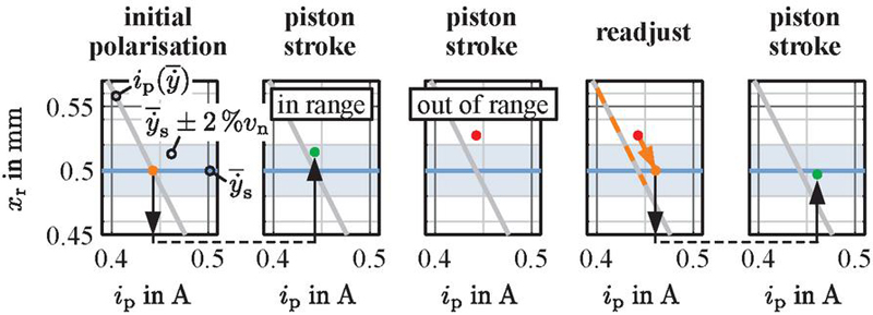
Figure 19 Procedure of closed loop control.
Initially, a polarisation is done after every setpoint change based on the control law . Afterwards, the piston is moved out and in by using the switching valve. The velocity is calculated and then compared with a permissible target range (here exemplary , see also Figure 18). If it is in the tolerance band, no repolarisation is required. Otherwise, the throttle opening has to be readjusted using an other polarisation current. The new one is calculated according to the Newton’s method with
| (6) |
using last polarisation current for and gradient from control law at . The piston velocity has to be checked again and repolarisations are done until the target range is reached.
The setpoint and disturbance profile from Figure 18 are run again with closed loop control. The results are illustrated in Figure 20. In order to consider the settling behaviour due to armature shift, two successive polarisations are not executed, if . This corresponds to the usual positive shift of the piston velocity (see Figure 16). Oscillations around the set value can thus be prevented.
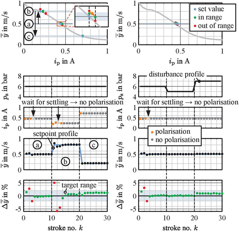
Figure 20 Behaviour of cylinder piston velocity for setpoint profile (left) and disturbance profile (right) by using closed loop control.
The velocity behaviour can be significantly improved. Usually, only one repolarisation is required for reaching the target range. At the setpoint , there is a slight oscillation due to changing gradient (curvature in transfer behaviour). In both profiles, suppressed repolarisations fulfil their purpose. However, conditions for prevention can be improved (see setpoint profile, ).
The closed loop control strategy enables a precise adjustment of a setpoint profile by compensating for disturbances. The strategy is basically energy-efficient, since only a few repolarisations are required depending on the target range. Furthermore, the implementation is simple and cost-effective, as only the usually already installed end stop sensors are evaluated.
The studies show the principal functionality. Various improvements can be implemented. From software perspective, this includes a better suited consideration of the curvature for gradient determination, an adaption of the dead band where repolarisations are avoided and self-learning algorithms for adapting the control law according to actual conditions. From hardware perspective, the sensitivity can be reduced by increasing the force potential of the actuator leading to a higher stiffness against disturbances.
6 Conclusion and Outlook
In this work, a potential application of novel multi-stable solenoids, an adaptive meter-out control of pneumatic cylinder drives is investigated, in order to set customised piston velocities. The meter-out control is realised by a given spool valve as throttle, since it has low disturbance influences. A specific multi-stable solenoid have been designed and built up for automating the throttle. The design is based on an analytical approach, which is validated with FE simulations. Measurements on the automated throttle demonstrate the resulting functionality in the required working range. The automated throttle has been integrated in a simple pneumatic cylinder drive for investigating the setting of piston velocities with its nominal and disturbance behaviour. Measurements show a nearly linear adjustability of piston velocity in a majority of the operating area and only small disturbance influences. A settling behaviour of the remanent armature position and thus the piston velocity is observed after multiple piston strokes, which is probably caused by slight pressure-dependent forces on the spool. On that basis, the setting of customised piston velocities is presented by using a feed forward and a closed loop control. With the feed forward control, piston velocities can be set with an accuracy of around , which should be sufficient for many applications. The closed loop control enables a higher accuracy of around due to purposeful repolarisations according to the actual piston velocity.
This work demonstrates only one potential application of novel multi-stable solenoids. The presented control concepts are basically adaptable to other applications, which would have to be investigated in detail. These include, for example, applications in hydraulics, but also many other usages in mechatronic systems.
Acknowledgement
The research presented in this paper is based on the project “Novel multi-stable electro-magneto-mechanical actuators based on variable remanent operating points of semi-hard- and hard-magnetic materials”, which is funded by the Deutsche Forschungsgemeinschaft (DFG, German Research Foundation) – 434232806.
Biographies
[1] E. Kallenbach, R. Eick, T. Ströhla, K. Feindt, M. Kallenbach, and O. Radler. Elektromagnete: Grundlagen, Berechnung, Entwurf und Anwendung. 5. Auflage. Wiesbaden: Springer Fachmedien Wiesbaden, 2018. ISBN: 978-3-658-14787-7 978-3-658-14788-4. DOI: 10.1007/978-3-658-14788-4.
[2] T. Roschke. “Potenzial bipolarer Magnete in Verriegelungs- und Hubanwendungen”. In: Innovative Klein- und Mikroantriebstechnik: Vorträge der ETG-/GMM-Fachtagung. Innovative Klein- und Mikroantriebstechnik, IKMT 2004. Darmstadt, Germany: Margret Schneider, 2004. ISBN: 3-8007-2816-8 978-3-8007-2816-9.
[3] L. Krauß. “Ein Beitrag zur Auswahl, zum Entwurf und zur Ansteuerung von bipolaren Elektromagneten, insbesondere für Magnetventile”. PhD thesis. Ilmenau, Germany: Technische Hochschule Ilmenau, 1984.
[4] L. C. Burmeister. NASA Contributions to Advanced Valve Technology – A Survey. revised and enlarged edition. NASA SP-5019. National Aeronautics and Space Administration, 1967.
[5] B. G. Johnson, S. E. Massey, and O. E. Sturman. “Sturman Digital Latching Valve”. In: Seventh Scandinavian International Conference on Fluid Power (SICFP2001). Linköping, Schweden, May 30–June 1, 2001, pp. 299–314.
[6] M. Olbrich, A. Schütz, T. Bechtold, and C. Ament. “Design and Optimal Control of a Multistable, Cooperative Microactuator”. In: Actuators 10.8 (Aug. 4, 2021), p. 183. ISSN: 2076-0825. DOI: 10.3390/act10080183. URL: https://www.mdpi.com/2076-0825/10/8/183 (visited on 01/06/2023).
[7] J.-P. Uusitalo. “A Novel Digital Hydraulic Valve Package a Fast and Small Multiphysics Design”. PhD thesis. Tampere, Finland: Tampere University of Technology, 2010.
[8] T. Kramer and J. Weber. “An Approach for Novel Energy-Efficient Multi-Stable Solenoids and the Demonstration of Its Fundamental Behaviour”. In: 18th Scandinavian International Conference on Fluid Power (SICFP 2023). 18th Scandinavian International Conference on Fluid Power (SICFP 2023). Tampere, Finland, May 30-June 1, 2023. URL: https://urn.fi/URN:ISBN:978-952-03-2911-2.
[9] T. Hüfner, O. Radler, T. Ströhla, T. Sattel, J. Wesselingh, A. Vogler, and D. Eicher. “A Note on Electromagnetic Gravity Compensation Actuators Based on Soft Electro-Permanent Magnets for Adjustable Reluctance Force”. In: (May 2017).
[10] S. G. Viëtor. “Tunable Magnets: Modeling and Validation for Dynamic and Precision Applications”. MA thesis. Technische Universiteit Delft, Aug. 28, 2018. URL: https://repository.tudelft.nl/islandora/object/uuid\%3Ab4f375ee-c52c-45de-b40a37d5722407d2.
[11] W. B. Hoekwater, E. Ronaes, and H. HosseinNia. “Hybrid Tunable Magnet Actuator: Design of a Linearized Force-Flux Tunable Magnet Actuator”. In: IEEE Transactions on Industrial Electronics 71.5 (May 2024), pp. 5073–5082. ISSN: 0278-0046, 1557-9948. DOI: 10.1109/TIE.2023.3285984. URL: https://ieeexplore.ieee.org/document/10155636/ (visited on 06/23/2024).
[12] H. Czichos, T. Saito, and L. R. Smith, eds. Springer Handbook of Materials Measurement Methods. Germany: Springer, 2006. 1208 pp. ISBN: 978-3-540-20785-6.
[13] T. Kramer and J. Weber. “Automation of Pneumatic Throttle Check Valves by Using Novel Multi-Stable Solenoids”. In: 14th International Fluid Power Conference (IFK 2024). Dresden, Germany, Mar. 19–21, 2024. DOI: 10.13052/rp-9788770042222.
[14] K. Schüler and K. Brinkmann. Dauermagnete: Werkstoffe und Anwendungen. Berlin, Heidelberg: Springer Berlin Heidelberg, 1970. ISBN: 978-3-642-93003-4 978-3-642-93002-7. DOI: 10.1007/978-3-642-93002-7. URL: http://link.springer.com/10.1007/978-3-642-93002-7 (visited on 01/03/2021).
Biography

Thomas Kramer received his diploma in Mechatronics from TU Dresden in 2011. Since 2013 he is working as research assistant at the Chair of Fluid-Mechatronic Systems (Fluidtronics), Institute of Mechatronic Engineering, Technische Universität Dresden, Germany. His research area mainly includes solenoids in fluid power and in similar applications. The focus here is on magnetic material measurements, various working principles, design and modelling, actuator measurements, control electronics and self-sensing position determination.
International Journal of Fluid Power, Vol. 25_4, 521–546.
doi: 10.13052/ijfp1439-9776.2545
© 2024 River Publishers