Formulation and Experimental Validation of an Agricultural Implement-Only MPR System for Maximum Compatibility with Existing Agricultural Tractors
Jacob Lengacher1,*, Xiaofan Guo1, Ryan Jenkins2 and Andrea Vacca1
1Maha Fluid Power Research Center Purdue University, Lafayette,
IN 47905 United States
2CNH Industrial, IL, 60523-4425 United States
E-mail: jlengac@purdue.edu
*Corresponding Author
Received 20 December 2024; Accepted 11 April 2025
Tightening emissions regulations and rising fuel costs have driven a desire across many industries for more efficient actuation systems. This is particularly true of the agricultural sector. An extremely common arrangement in this sector is the tractor and implement pairing, in which actuators on an implement are powered by a hydraulic supply system on the towing tractor. This arrangement complicates the development of energy efficient hydraulic systems, as many new system designs require modification of both machines to reap efficiency benefits. Past work by the authors’ team has demonstrated great potentials for Multi-Pressure-Rail (MPR) technology involving both the tractor and implement subsystems. However, applicability of this MPR technology in a more realistic scenario where only one vehicle is equipped with such technology was not addressed.
This work proposes an implementation of the MPR technology to an agricultural planter that allows significant savings, while only modifying the implement machine. This is done by manipulating the load sense network of a stock tractor to set system pressures to those required by the MPR system. This greatly reduces the barrier to implementation of MPR technology in agriculture. The work begins by outlining the reference machine for the system, then reviews the MPR system working principle. After this, the proposed expansion to the MPR concept is laid out and applied to the reference system. Finally, experimental validation is carried out, demonstrating up to a 35% reduction in system power consumption when paired with a state of the art, double-LS System tractor, and 15% with a single-LS System tractor.
Keywords: Multi pressure rail, agricultural hydraulics, compatibility, efficient hydraulics.
A growing world population corresponds naturally with increased demand for food [1]. This increased demand will naturally require more effective agricultural machinery to meet. Simultaneously, however, growing economic, environmental, and social pressures demand a reduction in carbon emissions [2]. These demands can only be reconciled by the development of more efficient agricultural systems capable of meeting the needs of the future in a sustainable way. One particularly common arrangement in existing agricultural systems is the tractor/implement pair, in which a tractor supplies power to a towed working implement. This arrangement is popular for its cost effectiveness; the most expensive components of the system (engine, transmission, pump) are kept aboard the tractor and can be reused across a variety of operations, such as planting, seeding, baling, and tillage, while the task specific actuators and tools are kept on the less expensive implement. Such power-transfer between machines can be done mechanically, via a rotary PTO shaft, but in recent years as the size of implements (and thus distance and flexibility of power transfer required) increases, a growing emphasis has been placed on hydraulic transfer of power. The state of the art for this arrangement is the load sensing (LS) system, in which the tractor supplies flow at a pressure set by the highest load user plus a known margin. For tractor-implement systems this is typically done through a “Remote Valve” arrangement, by placing quick connect hydraulic couplers after the LS control valves, leaving the actuators installed on the implement, to be connected when it is in use [3]. While this arrangement is very efficient when supplying single-actuator systems, or systems with multiple actuators with similar load pressure requirements, this system often suffers serious inefficiency when supplying multiple actuators at widely spread pressure levels [4], as demonstrated for the case of an excavator by Zimmerman in [5]. All of this combines to give agricultural fluid power systems an average energy efficiency of just 20%, as estimated by Oak Ridge National Laboratory [6].
A wide variety of solutions aiming to improve the efficiency of the LS system or replace it entirely have been proposed. Madau dynamically minimizes the load-sensing margin of a wheel loader system in [7] to reduce regulation losses. Tian and Stump apply a similar logic to an agricultural system in [8] also varying the margin of the compensator to enable even greater reduction in pump pressure [9]. Independent metering, in which the meter in and meter out valves are controlled independently with the goal of reducing unnecessary metering are also a common method of reducing unwanted losses [10]. Wydra pairs an independent metering LS system with an accumulator rail to allow for some load recovery potential in [11], showing in simulation up to 18.7% reduction in system energy consumption. These solutions are effective in reducing the power consumption of systems with relatively closely grouped actuator loads. They do not address the issue of load imbalance described in [5], however. Solving this problem requires more radical modifications of the system. The most natural and extreme modification is the addition of more pumps. Grouping actuators together by load and supplying these groups independently allows for reduction in regulation losses due to load imbalance. The natural conclusion of this is primary control hydraulics, in which one actuator is controlled by one pump, either by varying the speed or displacement of the pump. The latter method, displacement control, as implemented in [12] and [13] eliminates the need for throttling speed control, and ensures each actuator is supplied with exactly the pressure and flow required by the user. The former method has seen much interest in recent years as electrification, and thus variable-speed pumps (ePumps) have become a more common part of off-road actuation. Qu proposes an architecture for a small loader using an ePump for primary control of an actuator, reducing system power consumption by greatly reducing throttling losses and recovering energy from the lowering of a boom [14, 15]. All of these solutions have the potential to drastically reduce the power consumption of these hydraulic systems by doing away with regulation losses entirely and enabling energy recovery from overrunning loads. The limitation of the system is cost, however. The more actuators a system has, the less affordable and plausible primary control methods become. Busquets attempts to resolve this, proposing a pump sharing algorithm that allows for fewer pumps to be used to supply the system’s actuators in [16]. This strategy relies heavily on transient, well-characterized duty cycles, like those present in construction excavators, making them less suited for application to agricultural applications, where there may be many actuators with uncertain drive cycles.
Another option is switching to a pressure supplied logic. Pressure supplied systems decouple the flow requirements of the actuator and the pump, having the pump supply flow to keep a rail at a chosen pressure. This arrangement can be inefficient if poorly designed, but with proper design it can be quite efficient [17]. One option to reduce the throttling losses of pressure supplied systems is the use of hydraulic transformers. Proposed by Achten in [18], this concept mimics electrical systems by utilizing a pair of variable displacement hydraulic pump/motors connected in tandem. One serves as the motor, taking flow from a fixed constant pressure rail, to power the second, which pumps up to the pressure and flow required by the actuator. This architecture does away with throttling losses entirely and enables load recovery, but at the cost of somewhat increased component losses. This concept can be implemented in smaller, less dynamic forms as well, to generate multiple fixed rails from one main supply as seen in [19]. Li et al propose an architecture in which a constant pressure system is used, with small ePumps boosting or bucking pressure to that required by the actuators [20, 21], following a similar strategy to this.
A middle ground can be found in multi-pressure rail systems (MPR). These systems split the hydraulic supply into multiple pressure-supplied rails, then use selection valve sets to dynamically configure the rails attached to each actuator inlet and outlet. In [22], Lumkes proposed this idea with the goal of improving the controllability of pressure supplied systems, though power savings potential and controller design were not considered. It was then utilized to great effect by the STEAM excavator in [23] where the MPR system’s decoupling of actuator and prime mover speed enabled not only reduction in throttling losses, but engine management strategies and energy recovery as well.
Relevant to this work, the authors of this work proposed an implementation of an MPR architecture specific to the agricultural implement case in [24], using a stationary test rig to assess several options for the hydraulic supply and control logic. Then, in, [25] the proposed architecture was fully fleshed out and demonstrated in simulation. Finally, in [26] the system’s functionality and power savings potential were demonstrated on a full-scale prototype machine. This implementation of the architecture takes advantage of the unique properties of the agricultural system to further minimize throttling losses. The long lines and lack of overrunning loads present in the system remove the need for accumulators present in previously discussed MPR architectures, enabling the capability of dynamically selecting the pressure levels of the rails themselves. This enables the potential for a reduction of up to 48% in system power consumption. However, one limitation of this work, and much of the rest of the prior work done towards improving the efficiency of hydraulic systems, is that it requires the modification of both the hydraulic supply and the valving.
As discussed above, one of the fundamental advantages of the tractor/implement system utilized in agriculture is that one tractor can supply and work with a wide range of implements, keeping costs lower. Most of the previously discussed solutions require modifications to both the supply system (the tractor) and the valving (the implement). Even the MPR architecture proposed in [26], while it maintains the division between tractor and implement, requires extensive changes to both machines and to the interface between them. These changes would render the MPR implement unusable with a non-MPR tractor. The significant cost of requiring two entirely new machines to gain savings represents a severe barrier to adoption of the technology. In addition, the inability of the MPR implement to function properly with existing tractors is an undesirable logistical limitation for many farms, which need to be able to operate an implement, even if their primary tractor is out of commission.
This work aims to address these challenges by proposing an extension to the MPR architecture proposed for an agricultural implement in [26] that improves system efficiency using only modifications to the implement, paired with an unmodified state of the art tractor. Such a system could serve as a “bridge” implement, capable of working first with existing tractors, and gaining some savings potential, and gaining even further benefits when paired with a purpose-built MPR Tractor. This allows for a staggered adoption of MPR technology, lowering the entry barrier and likely improving adoption rate. To do this, the reference tractor/implement system will first be outlined, and the MPR architecture proposed in [26] will be briefly reviewed. After this, the working principle of the proposed compatibility-centric expansion to the system will be laid out. This principle will then be applied to the reference case, and validated via experiments taken on a full-scale prototype machine in real field conditions.
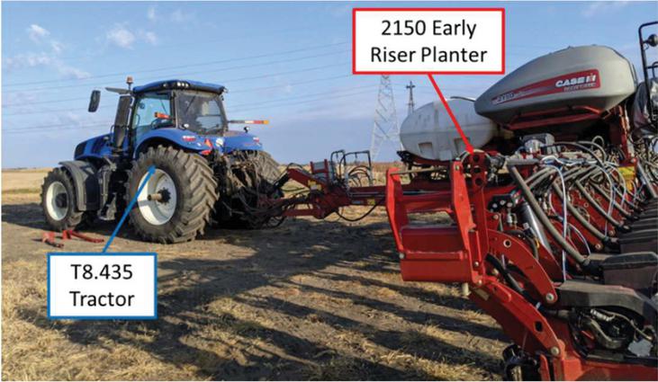
The reference machine for this work is a Case-IH 2150 Agricultural Planter supplied by a New Holland T8.435 Agricultural Tractor, as seen in Figure 1. This implement pairing is representative of the sort of system used across a wide range of North American farms for planting operations on soybeans and corn and is a worthwhile case for consideration as a result.
Figure 1 Reference tractor/implement system.
The tractor is outfitted with a parallel pair of simple pre-compensated load-sensing circuits able to supply implements via two different types of connections. The primary method is the remote valves, which are pre-compensated load-sensing valves with quick connections at the outlet and internal load-sense pickups. The second is the “Power Beyond” manifold, which uses a larger quick-connect pulling directly from the pump outlet, no control valve, and an external load-sense connection, relying on the implement to control the amount of flow required rather than a traditional compensated flow control valve [3]. This arrangement of multiple connection methods to a pair of parallel LS systems (henceforth, the “double pump” system) is typical of modern agricultural tractors sold in the U.S. Some older model tractors still in use in the U.S. and elsewehere might not possess this split hydraulic system arrangement, however, using only one pump to supply the remote connections. This arrangement (henceforth the “single pump” system) can be emulated on the reference machine by simply utilizing only one of the available LS circuits. The hydraulic architecture of the tractor can be seen in Figure 2. Both the 1 and 2 HP pumps will be utilized when simulating a double pump system, and only the 1 pump will be used when simulating a single pump system.
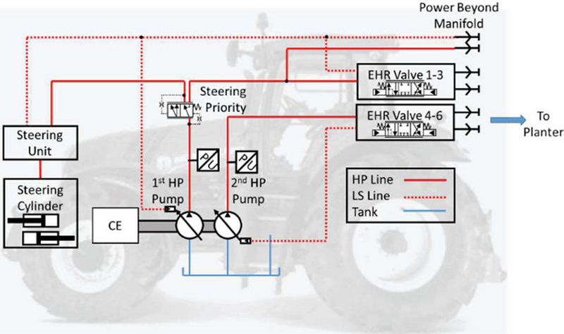
Figure 2 Simplified tractor schematic.
The actuators in use on the planter are shown in Figure 3 and outlined in Table 1. For simplicity, the figure shows the arrangement of the downforce cylinders, controlled through pressure reducing valves, as well as only one rotary function. In reality, as detailed in Table 1, the system contains more functions connected to the same hydraulic remote valve.
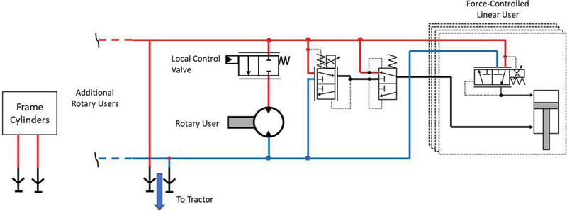
Figure 3 Simplified planter schematic.
The steady state rotary and steady state linear functions run continuously during planting in the field providing seed and fertilizer to the row units (via the Bulk and Vacuum fans and Fertilizer pump), powering the row units (via the compressor and alternator), and ensuring consistent ground contact and planting depth (via the HDPCs and WMCs). The transient linear functions run far less consistently, serving only to raise and lower the planter toolbar during headland turns or reconfigure the frame arrangement for transport.
Table 1 Hydraulically actuated planter functions
| Steady State Rotary Functions | |
| (Powered by Hydraulic Motors) | Purpose |
| Alternator | Power planter electronics |
| Bulk Fill Fan | Move seed to row units |
| Compressor | Power planter pneumatic actuators |
| Fertilizer Pump | Provide fertilizer to row units |
| Vacuum Fan | Provide suction for seed metering in the row units |
| Steady State Linear Functions | Purpose |
| Hydraulic Down Force Cylinders (HDPCs) | Maintain consistent ground contact and planting depth of row units |
| Weight Management Cylinders (WMCs) | Transfer weight across the planter width for consistent ground contact of each row unit |
| Transient Linear Functions | Purpose |
| Frame Cylinders | Raise and lower toolbar to begin / end planting process |
To reduce the number of connections between the tractor and planter the steady state planting functions are grouped into two circuits based on their physical position on the planter, and connected to a pair of tractor remote valves supplied by the same tractor LS system. These remote valves are opened fully and flow is controlled via the local flow control valves on the planter. The transient cylinders are supplied more traditionally using a third remote valve for metering control. This arrangement allows for more complex control on the planter and makes the planter independent of the control capabilities of the tractor, but it comes at the cost of system efficiency. A conflict in control occurs due to the position of the load-sense pickup between the two control valves. As shown in Figure 4, the load-sense pump attempts to maintain a fixed margin across the remote valve, effectively controlling flow through that valve. Simultaneously, the local flow control valves, either via hydraulic compensation or an electronic controller, attempt to control flow to the actuators by throttling flow supplied from the outlet of the remote valves. This leads to a conflict; the pump upstrokes, increasing flow through the remote valve to try to meet its margin. Simultaneously the control valve compensators close, trying to maintain their own margins leading to a net increase in the line pressure between the valves. This increase in pressure is passed through the LS network to the pump, causing it to further increase its displacement, and continue the cycle. For most applications, equilibrium occurs when pressure saturation is reached, with the relief valve in the LS line limiting the pump displacement and system pressure. This leads the system to behave not like an LS system, but like a constant pressure system, with the rail pressure set at the pump’s maximum pressure, leading to very low system efficiency but good control characteristics. These control benefits owe to the decoupling of the supply flow rate from the actuator flow rate which allows actuator speed to be controlled entirely by the local flow control valve. This conflict is discussed in detail and demonstrated mathematically in [27].
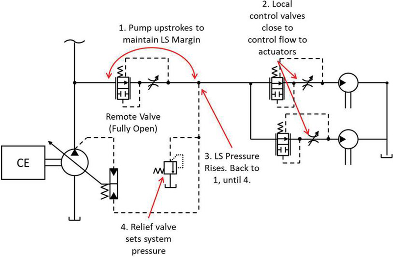
Figure 4 Control conflict due to series control valves.
The MPR Architecture, as presented in [26] aims to improve the system efficiency while maintaining its good controllability by switching from a flow-controlled logic like LS to a pressure-controlled logic. The proposed system, shown in Figure 5 is supplied by two pressure rails whose pressure can be controlled by varying the flow provided to them. Thanks to the long lines and large capacitance of the planter, this can be achieved without the need for accumulators. Rotary actuators are supplied via pressure selection and control valve manifolds which control what rails are connected to the inlet and outlet of each actuator, and then control the speed of the actuator by throttling flow from those rails. The force controlled linear actuators (the HDPCs and WMCs) are connected permanently from HP to LP due to their continuous high load requirements.
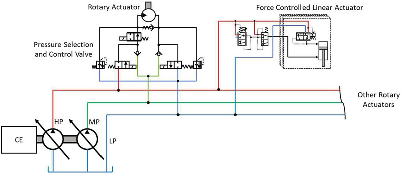
Figure 5 MPR architecture overview.
The pressure levels of the different rails are optimized to minimize the total system throttling losses while ensuring all actuators get the required flow, following a logic laid out in [26]. In this work, two control logics were proposed. The first varies both the high and medium pressure levels to fully optimize the system throttling losses, called “Variable HP MPR”. The second stemmed from the recognition that the downforce system always requires close to maximum pressure, resulting in the high-pressure rail spending most of its time very close to that level. This fact is leveraged by the second control logic, called “Fixed HP MPR” to reduce control effort and improve system stability by locking the high-pressure rail at a high pressure based on the peak actuator needs, and only optimizing the medium pressure rail. The results presented in [26] demonstrates that this logic substantially improves dynamic behavior at only a slight cost in terms of reduced savings. To optimize the pressure levels and operating modes of the system a controller was devised. It assigned the HP rail to either a pressure just exceeding the required pressure of the highest load user (for Variable HP MPR), or to the maximum pressure required by at any point by an actuator in the system (for Fixed HP MPR). The medium pressure rail was then selected by calculating the system losses at key points based on the pressure requirements of the actuators and discontinuities in the loss cost function. After the rail pressures were selected, each actuator was assigned to the rail combination that minimized system loss.
The previously proposed architecture required modification to both the tractor and the implement. The control logic and switching are carried out on the planter, while the tractor supplies the required pressures. This represents a substantial barrier to potential implementation, due to requiring changes to both systems. This work proposes an alternative method of achieving the Fixed HP MPR control logic on an implement that can be achieved using an unmodified, state-of-the-art double-pump tractor, as well as how this Compatible MPR System hardware can be used to restore LS operation, even with a single-pump tractor.
There are some requirements for this unmodified tractor. Principally, it must have remote valves, a power beyond manifold, and a two-pump, divided LS system (characteristics of a double pump system.) This is true of the reference tractor for this work, and a wide range of other machines currently on the market within the 300–400 hp size range of the reference system, and in larger vehicles. The pressure control is then implemented by “tricking” the tractor’s LS system into enacting MPR logic. The high-pressure level is set by exploiting the control conflict discussed in Section 3. The HP rail is connected to one of the LS circuits via the remote valves, and the remote valves are opened fully. When flow is commanded by the actuators, the control conflict drives the LS pump to maximum pressure, giving the HP rail close to its desired pressure level. Notably, this level cannot be selected based on implement needs as in the two-machine MPR system. The MP rail still requires variable control, however, which is achieved using the power-beyond manifold. The MP rail is supplied by the power beyond port, and thus the second LS pump, and uses an electronically regulated pressure control valve to control the LS pressure seen by the power beyond manifold’s LS port. This working principle applied to the reference machine is shown in Figure 6.
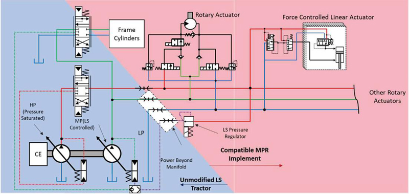
Figure 6 Highly compatible MPR system arrangement.
As can be seen, the HP and MP rails are connected and controlled as outlined above. Notably, the transient linear functions are connected to the same pump as the MP rail, ensuring that their LS functionality is maintained. With this supply arrangement, the MPR implement downstream from the adaptor can be left largely unchanged from that previously outlined, using pressure selection and control valves to handle speed control and mode switching for the rotary functions, while the force controlled linear functions are connected continually from HP to LP.
A similar arrangement can be used with single pump tractors as well, though this arrangement will see far lower savings. In this arrangement, the MP and HP rails are connected to one another internal to the implement by opening selected pressure switching valves within the MPR system. The MP rail is then connected to the tractor via the power-beyond port. The LS regulator then bleeds flow from the supply rail to control the system supply pressure, as was done for the Highly Compatible arrangement above. This Bare Minimum Compatible arrangement is illustrated in Figure 7.
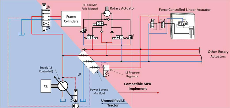
Figure 7 Bare minimum compatible MPR system arrangement.
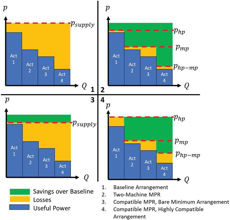
Figure 8 Qualitative pressure/flow plots for proposed MPR system arrangements and baseline.
This arrangement is achievable using the same planter and adapter hardware as in the Highly Compatible system, connected differently and running a different control logic. In this arrangement, the supply rail pressure is set using an LS logic to just above the highest load user. This arrangement resolves the flow regulation conflict described above and restores load-sensing functionality, however it does nothing to address the problem of load imbalance. As a result, while the system is likely to yield some efficiency improvements, there will still be significant throttling losses present. Figure 8 compares the theoretical pressure/flow plots for the baseline system (1), Two-Machine MPR system (2), Bare Minimum compatible Arrangement (3), and Highly Compatible MPR Arrangement (4) systems. As can be seen, the baseline system’s supply pressure is locked at the maximum level by the control conflict. The Two-machine MPR system greatly reduces losses by placing the two pressure rails to minimize losses. The Highly Compatible MPR arrangement comes close to this, but lacks the ability to lower the HP rail pressure, resulting in slightly higher losses. Finally, the bare-minimum compatible arrangement can only restore LS operation, resulting in a slight reduction in losses, but much smaller than the other MPR arrangements.
To validate system functionality and savings potential, the proposed architecture was then implemented on the reference machine. This modification was done in addition to the modifications presented in [26]. Figure 9 shows the ISO schematic of the modified planter, including key sensor locations, along with the structure of the DAQ and control system for both the tractor and planter.
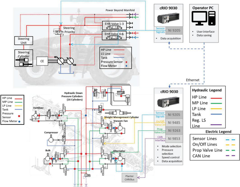
Figure 9 Implement-only MPR architecture applied to reference machine.
As can be seen above, the control logic was implemented using an NI cRIO system. As in previous work, two cRIOs were used, one on the planter and one on the tractor. For this system, however, all control was carried out on the planter, with the tractor system serving only to monitor the behavior of the tractor hydraulic supply. The hydraulic modifications to the implement, beyond those shown in prior work, are pictured in Figure 10. The hydraulic modifications made are implemented as a sort of adapter, connecting the MPR implement’s quick connectors to the correct ports on the tractor and siphoning flow from the HP line to run the regulator.
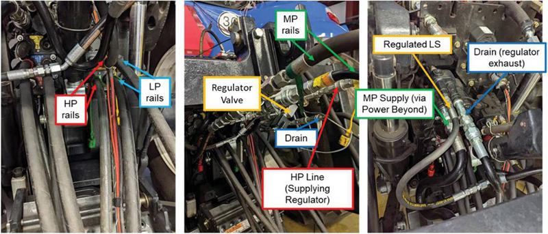
Figure 10 Compatible MPR adapter hydraulic implementation.
To assess the effectiveness of the system and ensure a fair comparison with prior work, the same mission profile as in [26] was used. This cycle was provided by the vehicle manufacturer and contains two common working conditions; one corresponding to normal planting conditions, and one corresponding to a more aggressive high-speed planting case. Each test case was run at several engine speeds. The mission profile used is shown in Table 2, with all values normalized against their maximum value.
Table 2 Normalized validation mission profile
| Vehicle | Engine | Vacuum | Alternator | HDPC | Wing | Bulk | Liquid | ||
| Drive Cycle Name | Crop | Speed (%) | Speed (%) | (%) | (%) | Force (%) | Force (%) | Fill (%) | Fert. (%) |
| Baseline – Popcorn | Popcorn | 50% | 71% | 57% | 60% | 50% | 55% | 70% | 13% |
| 86% | |||||||||
| 100% | |||||||||
| High Speed – Popcorn | Popcorn | 83% | 86% | 71% | 80% | 100% | 55% | 70% | 13% |
| 100% |
A full set of tests were conducted for both the Highly Compatible and Bare Minimum Compatible arrangements. Tests were taken in a similar method to prior work, on a quarter-mile test field strip at a Purdue farm, as shown in Figure 11. Each test was begun by starting the recording software, lowering the planter toolbar, planting for the length of the field, then raising the toolbar before stopping the recording. This ensured that ample steady state regions could be recorded to assess the power savings potential of the system at each condition. Further, the use of the same mission profile and testing field allows the results from this work to be compared with the Two-Machine MPR and baseline tests presented in the prior work.
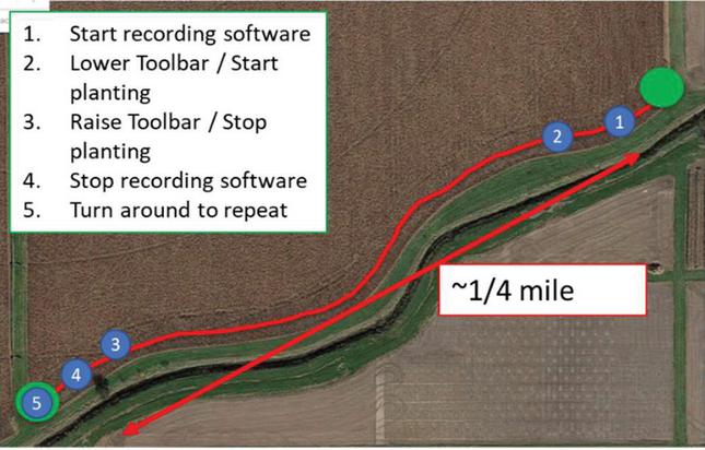
Figure 11 Test field and plan.
Figure 12 shows the time series behavior of the highly compatible MPR system, including a selection of actuator modes and rail pressure levels (only a selection of representative actuators are shown in the interest of clarity). Pressures shown are normalized against the system’s maximum pressure and flows against the baseline system’s flow output for a given condition.
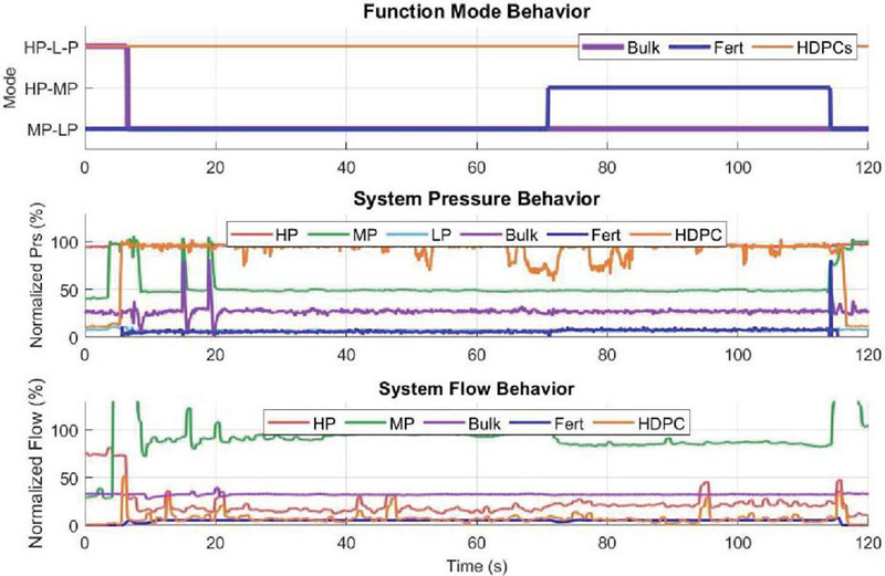
Figure 12 Time series results for highly compatible implement-only MPR system.
The system pressure behavior is as expected, with the HP rail locked at maximum pressure, and the MP rail settling to roughly 50% of the system maximum pressure. Initially, all the rotary actuators connect from MP to LP, however once the fertilizer has reached its target speed, it no longer needs to accelerate, but only to keep spinning, dropping its load enough to switch to connecting from HP to MP. Meanwhile the HDPCs are supplied constantly from HP to LP.
All functions switch to be supplied by HP to LP at the beginning (0–10 seconds) and end (115–120 seconds) of the cycle. This coincides with the toolbar of the planter, which is powered by the MP pump (as shown in Figure 6) being lowered and raised, and occurs because the MP pump’s LS functionality is maintained. When the bar is moved, the MP pump pressure rises, placing the MP and HP rail pressures close together and leading the system to function at a suboptimal point. This is only a transient region, however, and the system quickly stabilizes and returns to more optimal operation. This disturbance can also be seen in the system’s flow behavior.
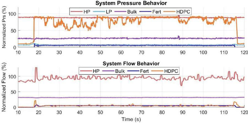
Figure 13 Time series results for bare minimum compatible implement-only MPR system.
The flow behavior for the system is mostly steady, with the highest flow users having very steady commands (similar to the bulk flow trace shown.) The HP flow does vary more significantly since it is supplying the more unsteady load in the form of the HDPCs. At 75 seconds, when the fertilizer switches from MP – LP to HP – MP, it can be seen that the MP rail flow reduces by roughly twice the flow drawn by the fertilizer. This occurs because the HP pump is now supplying the fertilizer’s flow, and returning flow to the MP rail, allowing for a small measure of recirculation.
Similarly, Figure 13 shows the time series behavior for the Bare-Minimum Compatible MPR arrangement. Because the system does not have modes, only the system pressures are shown. The supply rail pressure can be reduced slightly from the maximum value to which it would have settled without LS restoration. This improvement is limited by the HDPC system, which requires a much higher supply pressure than the other users to operate correctly. This leads to significantly higher throttling losses than in the Highly Compatible System.
The single-rail arrangement also means that the flow behavior of the Bare Minimum compatible system is not remarkable, with all functions being supplied by the single HP pump.
Table 3 shows the improvement for the two configurations in power consumption over the baseline system. For this comparison, hydraulic power at the systems’ pump outlets were calculated based on the pump outlet pressure and outlet flowrate and then averaged over the selected steady state region. The values are normalized as in the plots above, and the resultant power consumption is represented as a percentage of the baseline power for the given operating condition. The Highly Compatible arrangement is able to supply the majority of the flow to the planter via the MP rail, while only outlying loads (such as the HDPC array) are supplied via the HP rail. This arrangement gives it a significant improvement over the Bare Minimum Compatible arrangement, which supplies all of its flow at the HP level.
Table 3 Steady state power consumption of the proposed compatible MPR system
| Operating | Bare Minimum Compatible | Highly Compatible System | ||||||
| Condition | ||||||||
| Normal | 88.2% | 98.1% | 86.6% | 94.1% | 51.0% | 27.7% | 75.2% | 64.4% |
| High Speed | 92.8% | 99.1% | 92.0% | 95.1% | 57.7% | 34.9% | 66.1% | 71.4% |
The systems’ reductions in power consumption are then compared with the Two-Machine, Variable HP MPR version of the system presented in [26] averaged across the tests taken in Table 4.
Table 4 Pump power consumption results compared with tractor/implement MPR
| Operating Condition | Pump Power Reduction (%) | ||
| Two-Machine | Highly | Bare Minimum | |
| Solution: | MPR [26] | Compatible MPR | Compatible MPR |
| Normal | 48.8 | 35.6 | 13.4 |
| High-Speed | 44.0 | 28.6 | 8.0 |
As can be seen in the table, each level of compatibility comes with some reduction of efficiency under normal planting conditions relative to the higher tech level system, with the Two-Machine system saving nearly 50%, the Highly Compatible saving around 35%, and the Bare Minimum saving less than 15%. The reason for the gap between Bare Minimum and Highly Compatible arrangements is clear. The Bare Minimum arrangement system uses the same hardware as the Highly Compatible arrangement but, without the ability to supply two discrete pressure levels, savings potential comes only from restoring LS functionality. As a result, due to the load imbalance between the HDPCs and other users, all flow to the rotary functions is throttled significantly. The Highly Compatible and Two-Machine systems both can address the issue of load imbalance leading to much greater efficiency improvement.
The reason for the gap in efficiency between the Two-Machine and Highly Compatible MPR systems is less immediately obvious but owes to two factors. First, the Two-Machine system as described in [26] places the HP line at roughly the pressure selected by the Bare-Minimum arrangement-roughly 88% of the system saturation pressure. Because it uses the control conflict to set its maximum pressure, the Highly Compatible arrangement does not have the ability to control where the HP pressure is set, resulting in it settling at 95–100% of system saturation pressure. This leads to a small throttling loss on any function pulling from the HP line. The second source for this difference is regulation losses. The Two-Machine MPR system used a purely electrical controller to regulate rail pressure, pulling in pressure sensor values and commanding the pump displacements to maintain those pressures at the target value. The Highly Compatible MPR arrangement carries out this control by controlling the LS pressure at the power-beyond port, but this regulation leads to a small, constant flow loss in order to keep the line at the proper pressure, further hurting efficiency. Finally, the two-machine system supplies the actuators directly from the pump outlet, bypassing the power beyond manifold or EHR valves through which the Highly Compatible MPR system is supplied. This results in a larger throttling margin being required for the highly compatible system, increasing throttling losses.
This work set out to design an MPR-based architecture capable of improving the efficiency of a tractor-planter system while only modifying the implement. An expansion to the basic agricultural MPR architecture was proposed allowing the system to function in tandem with a standard, double pump LS tractor. In addition, an alternative working mode using the same hardware to restore LS functionality without implementing MPR logic was proposed as well, ensuring compatibility with single-pump tractors. The system working principles were detailed and schematics were presented. The architecture was then implemented on a full-scale prototype planter and tested with both Highly Compatible and Bare Minimum Compatible arrangements. Field test results in typical planting conditions demonstrated 35% power savings over the unmodified system for the Highly Compatible system, and only 13% for the Bare Minimum system. This improvement was less than that demonstrated in [26] for a Two-Machine MPR system, but substantial, and its requiring modifications to only one machine represents a significantly smaller barrier to adoption for MPR technology.
This work was carried out in partnership with CNH Industrial, and funded by DOE Project DE-EE0009201, A New Approach for Increasing Efficiency of Agricultural Tractors and Implements.
[1] D. Wrachien, B. Schultz and M. Goli, “Impacts of population growth and climate change on food production and irrigation and drainage needs: A world-wide view,” Irrigation and Drainage, pp. 981–995, 2021.
[2] A. Masia, “Greenhouse Gas Emissions-Off Highway Vehicles Solutions and Future Trends,” Maha Fluid Power Research Center, Lafayette, IN, 2022.
[3] K. Stoss, J. Sobotzik, B. Shi and E. Kreis, “Tractor Power for Implement Operation – Mechanical, Hydraulic, and Electrical: An Overview,” in 2013 Agricultural Equipment Technology Conference, Kansas City, Missouri, USA, 2013.
[4] A. Vacca and G. Franzoni, Hydraulic Fluid Power Fundamentals, Applications, and Circuit Designs, Wiley, 2021.
[5] J. Zimmerman, M. Pelosi, C. Williamson and M. Ivantysynova, “Energy Consumption of an LS Excavator Hydraulic System,” in ASME International Mechanical Engineering Congess and Exposition, 2009.
[6] L. J. Love, E. Lanke and P. Alles, “Estimating the impact (energy, emissions and economics) of the US fluid power industry,”, Oak Ridge National Laboratory, Oak Ridge, TN, 2012.
[7] R. Madau, A. Vacca and F. Pintore, “Energy Saving on a Full-Size Wheel Loader Through Variable Load Sense Margin Contro,” J. Dyn. Sys., Meas., Control., 2021.
[8] X. Tian, P. Stump, A. Vacca, S. Fiorati and F. Pintore, “Power-Saving Solutions for Pre-Compensated Load-Sensing Systems on Mobile Machines,” in Transactions of the ASABE. 64(5), 2021.
[9] P. Stump, X. Tian, J. Lengacher, R. Jenkins and S. Fiorati, “Combined Pump and Compensator Margin Control for Pre-Compensated Load Sensing Architecture: Implementation and Experiments,” in Fluid Power Systems Technology, Sarasota, FL. USA, 2023.
[10] Z. e. a. Quan, “A Survey of Powertrain Technologies for Energy-Efficient Heavy-Duty Machinery,” Proceedings of the IEEE, vol. 109, no. 3, pp. 279–308, 2021.
[11] M. Wydra, G. M. and B. Weiss, “An Approach to Combine an Independent Metering System with an Electro-Hydraulic Flow-on-Demand Hybrid-System,” in The 15th Scandinavian International Conference on Fluid Power, Linköping, Sweden, 2017.
[12] J. Zimmerman, Toward Optimal Multi-Actuator Displacement Controlled Mobile Hydraulic Systems, West Lafayette: PhD Thesis: Purdue University, 2012.
[13] N. Daher and M. Ivantysynova, “Yaw stability control of articulated frame off-highway vehicles via displacement controlled steer-by-wire,” Control Engineering Practice, pp. 46–53, 2015.
[14] S. Qu and et al., “A high-efficient solution for electro-hydraulic actuators with energy regeneration capability.,” Energy, vol. 216, 2021.
[15] S. Qu, D. Fassbender, E. Busquets and A. Vacca, “Formulation, Design and Experimental Verification of an Open Circuit Electro-Hydraulic Actuator,” in Global Fluid Power Symposium, 2020.
[16] E. Busquets, Advanced control algorithms for compact and highly efficient displacement-controlled multi-actuator and hydraulic hybrid systems, West Lafayette: Purdue University: PhD Thesis, 2016.
[17] W. Shen, H. Huang, Y. Pang and X. Su, “Review of the Energy Saving Hydraulic System Based on Common Pressure Rail,” IEEE Access, pp. 665–669, 2017.
[18] P. Achten, Z. Fu and G. Vael, Transforming future hydraulics: a new design of a hydraulic transformer, Linkoping, Sweden, 1997.
[19] J. Lengacher, P. Stump, A. Vacca, R. Jenkins, F. Pintore and S. Fiorati, “Application of the Hydraulic Transformer Concept to Reduce Throttling Loss in a Multiple-Function Load Sensing System,” in ASME/BATH 2023 Symposium on Fluid Power and Motion Control, Sarasota, Florida, 2023.
[20] P. Li, J. Siefert and D. Bigelow, “A hybrid hydraulic-electric architecture (HHEA) for high power off-road mobile machines,” in Proceedings of the ASME/BATH 2019 Symposium on Fluid Power and Motion Control, Longboat Key, FL, USA, 2019.
[21] J. Siefert and P. Li, “Optimal Control of the Energy-Saving Hybrid Hydraulic-Electric Architecture (HHEA) for Off-Highway Mobile Machines,” IEEE Transactions on Control Systems Technology, 2021.
[22] J. Lumkes and J. Andruch, “Hydraulic Circuit for Reconfigurable and Efficient Fluid Power Systems,” in The 12th Scandinavian International Conference on Fluid Power, Tampere, Finland, 2011.
[23] M. Vukovic, R. Leifeld and H. Murrenhoff, “STEAM - A hydraulic hybrid architecture for excavators,” in 10th Int. Fluid Power Conference, Dresden, Germany, 2016.
[24] X. Guo, R. Madau, J. Lengacher, A. Vacca and R. Cardosa, “Multi-Pressure Rail System Design with Variable Pressure Control Strategy,” in The 13th International Fluid Power Conference, Aachen, Germany, 2022.
[25] X. Guo, J. Lengacher and A. Vacca, “A Variable Pressure Multi-Pressure Rail System Design for Agricultural Applications,” Energies, vol. 15, 2022.
[26] X. Guo, J. Lengacher and A. Vacca, “Quantification of energy savings due to the adoption of of Multi-Pressure Rail technology in an Agricultural Tractor – Implement system through experiments,” Energy Conversion and Management, 2025 (Under review; draft available upon request).
[27] X. Tian, X. Guo, P. Stump, A. Vacca, S. Fiorati and F. Pintore, “A pressure control method for increasing the energy efficiency of the hydraulic system powering agricultural implements,” Proceddings of the Institution of Mechanical Engineers, Part I: Journal of System and Control Engineering, vol. 238, no. 6, 2024.

Jacob Lengacher received his bachelor’s degree in Mechanical Engineering from Purdue University in 2021, and is currently pursuing his PhD in Agricultural Engineering from Purdue University, working with the Maha Fluid Power Research Center. His research interests include the design of efficient hydraulic-electric systems with a focus on agricultural and mining applications.

Xiaofan Guo received his bachelor’s degree in Mechanical Engineering from Purdue University in 2015, and his Master’s degree in Mechanical Engineering from Purdue University and PhD in Mechanical Engineering from Purdue in 2017 and 2024 respectively. He is currently working as a systems engineer for Bosch Rexroth.

Ryan Jenkins received his bachelor’s degree in Mechanical Engineering from Brigham Young University in 2014, and his PhD in Mechanical Engineering from Purdue University in 2019. He now works as a Hydraulics Systems Innovation Engineer for CNH Industrial.

Andrea Vacca is the Maha Fluid Power Faculty Chair and a Professor at Purdue University. Dr. Vacca received his doctoral degree from the University of Florence (Italy) in 2005, and he joined Purdue University in 2010 after being an Assistant Professor at the University of Parma (Italy). Fluid power technology has been Dr. Vacca’s major research interest since 2002. Dr. Vacca authored the textbook “Hydraulic Fluid Power” by Wiley, more than 150 technical papers and 18 patents. In 2019 he received the J. Bramah medal from the U.K. Institution of Mechanical Engineers. He is a fellow of the American Society of Mechanical Engineers (ASME), and a former chair of the Fluid Power Systems and Technology Division (FPST) of ASME, and of the Fluid Power Division of the Society of Automotive Engineers (SAE). Dr. Vacca is also one of the Directors of the Global Fluid Power Society (GFPS)
International Journal of Fluid Power, Vol. 26_2, 263–288.
doi: 10.13052/ijfp1439-9776.2626
© 2025 River Publishers