Industry 4.0: Review of the State of the Art in Fluid Power Research and Industry
Malte Becker*, Selim Karaoglu, Faried Makansi, Judith Radtke and Katharina Schmitz
RWTH Aachen University, Institute for Fluid Power Drives and Systems (ifas), Campus-Boulevard 30, 52074 Aachen, Germany
E-mail: malte.becker@ifas.rwth-aachen.de; selim.karaoglu@ifas.rwth-aachen.de; faried.makansi@ifas.rwth-aachen.de; judith.radtke@ifas.rwth-aachen.de; katharina.schmitz@ifas.rwth-aachen.de
*Corresponding Author
Received 12 February 2025; Accepted 06 November 2025
Abstract
Over a decade after the introduction of the Industry 4.0 vision, digital transformation remains a central imperative for industrial companies aiming to maintain competitiveness amid increasing economic and ecological pressures. As various Industry 4.0-implementations enter industrial practice, a more precise understanding of the requirements and opportunities for digital transformation has emerged across sectors. The fluid power domain, an essential part of many industrial systems, has likewise advanced efforts to develop Industry 4.0-compliant components and systems in recent years. This contribution provides a systematic overview of the current state of digital transformation in the fluid power, with a particular focus on Industry 4.0-concepts such as the Asset Administration Shell. The study offers a structured categorization of Industry 4.0-related research in the fluid power, mapping relevant publications and their thematic focus. Key use cases in which Industry 4.0-concepts are already integrated, including automated commissioning and simulation-based engineering, are presented in detail. The findings indicate significant progress in areas such as the integration of Industry 4.0-concepts into industry-relevant use cases, and the standardization of interfaces and component descriptions.
Keywords: Industrial Internet of Things, Industry 4.0, Industrie 4.0, Asset Administration Shell, Smart Technologies, Interoperability, Fluid Power, Systems Engineering.
1 Introduction
In the following section, the motivation, central research question guiding this contribution, and the applied methodology are introduced.
1.1 Motivation and Research Question
Industry 4.0 describes the transformation of industrial value creation toward flexible, globally networked ecosystems driven by data-centric business models in which customer value and solution orientation take center stage [1]. Sovereignty, interoperability, and sustainability are recognized as key success factors that define the framework for a competitive and socially responsible digital economy [1].
As a key paradigm of modern industrial development, Industry 4.0 fosters networked and data-driven value chains [2]. By emphasizing interoperable systems and collaborative data sharing, it enhances resilience, sustainability, and the capacity for flexible, digitally connected production processes [2]. However, despite significant attention, the practical adoption of Industry 4.0 concepts in fluid power technology remained limited as late as 2018 [3].
This contribution addresses the research question: To what extent has fluid power research and industry progressed in implementing the concepts and objectives associated with the vision of Industry 4.0? This builds upon an earlier question posed by [3]: “Are we really on track concerning Industry 4.0?” This question was first examined in 2018, when Industry 4.0 was still in its infancy. Building upon that initial inquiry, the present work systematically analyzes the progress and developments achieved in Industry 4.0 implementation in fluid power until 2025.
In the following sections, relevant technological aspects of Industry 4.0 are described and discussed in the context of fluid power. Section 2 presents the vision of Industry 4.0. This is followed in Section 3 by a discussion of existing reference architectures and the topic of interoperability (see Figure 1). These reference architectures aim to align companies regarding Industry 4.0 and thus serve as a basis for implementing Industry 4.0-concepts. In this context, interoperability is also considered and explained, which is decisive for Industry 4.0.
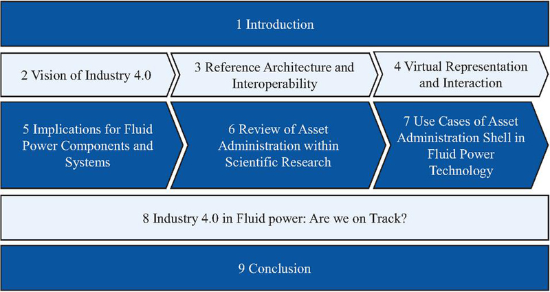
Figure 1 Overview of the sections.
Section 4 introduces virtual representation technologies. Since these virtual representations introduce new requirements for fluid power components and systems, the corresponding physical aspects, such as sensors or on-board electronics that align with Industry 4.0, are presented in Section 5. Section 6 introduces the Asset Administration Shell in the context of fluid power and provides a concise review of the current state of research on Asset Administration Shells within this sector. After reflecting on both virtual and physical aspects of Industry 4.0 in fluid power, comprehensive use cases for Industry 4.0 applications, such as automated commissioning, are presented in Section 7. Section 8 discusses whether Industry 4.0 in fluid power is already on track. Finally, Section 9 concludes with a summary of the findings.
1.2 Methodology
To systematically determine the current state of the art in fluid power research and industry in the context of Industry 4.0, a structured scoping review approach adapted from Ritschl et al. [4] was applied. Industry 4.0 encompasses a broad spectrum of concepts technologies and application domains. However, its maturity and implementation level vary significantly across sectors. While general progress in Industry 4.0 has been widely studied the degree to which the fluid power industry is aligning with the vision of Industry 4.0 has not been comprehensively examined in recent years.
The review process followed the first five steps of the established six-step methodology: identification of the research question, identification of relevant studies, selection and quality assessment of studies, data collection, and synthesis of results. The final step, stakeholder consultation, was omitted in this study. The literature search was conducted in relevant scientific databases using predefined search strings. The resulting publications were filtered through abstract-based screening using inclusion criteria such as publication date, degree of relevance to fluid power, and explicit coverage of Industry 4.0 use cases and enabling technologies. The remaining studies underwent detailed content analysis to extract, classify, and contextualize findings with respect to Industry 4.0 principles and developments.
2 Vision of Industry 4.0
In the following chapter, the emergence of Industry 4.0 and the shift from centralized to distributed systems is introduced.
2.1 Emergence of Industry 4.0
In the frame of the digital transformation, the term “Industrie 4.0” emerges [5]. The term was first introduced in 2011 at Hannover Messe [6] and described an initiative of the German government as part of the high-tech strategy to support the fourth industrial revolution [7]. Although international paper also refer to the German term “Industrie 4.0” [8, 9], this contribution consistently uses the English term Industry 4.0 (I4.0) for clarity and uniformity when providing a general description of Industry 4.0. Exceptions are made for obvious proper names.
The term fourth industrial revolution refers to the previous three revolutions, see Figure 2. The first industrial revolution is characterized by the introduction of mechanical manufacturing equipment driven by water or steam power. The second industrial revolution introduced mass production with electric drives. Furthermore, the third industrial revolution is associated with the increasing automation of manufacturing processes, driven by employing electronics and information technologies. The fourth industrial revolution is based on Cyber Physical Systems (CPS). In context of the manufacturing industry, cyber-physical systems encompass intelligent machines, storage systems, and production facilities that can independently exchange information, initiate actions, and coordinate control among themselves [7].
As a result of connecting real and virtual objects and processes, I4.0 aims to establish new business models and increase the efficiency of current industrial applications [10]. In particular, I4.0 is intended to enable the large-scale production of customized products through a flexible production environment and the development of processes to allow self-optimizing, self-configuring, and self-diagnostic systems [11]. In the course of this, I4.0 should enable production sites in high-wage countries, particularly, to hold their own in the face of increasing global competition [6]. Internationally, related concepts to I4.0 are known as the Industrial Internet of Things (IIoT) [12].
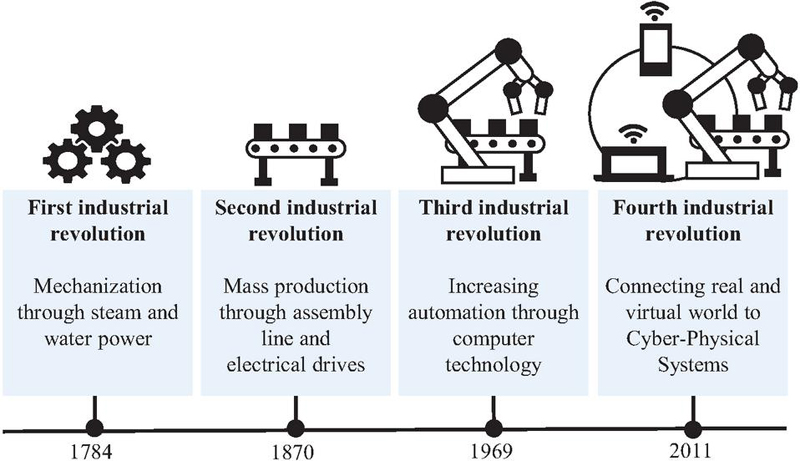
Figure 2 Industrial revolutions [7].
2.2 From Centralized to Distributed Systems
I4.0 is leading to a paradigm change in the corporate structure. Networked, decentrally organized or partially self-organizing services, which are located directly on functional modules, dissolve the classic automation pyramid [13]. The automation pyramid describes the classic hierarchical corporate structure with a centralized organizational instance and is increasingly changing towards a Service-oriented Architecture (SoA) [14]. SoA is an emerging approach that addresses the requirements of loosely coupled, standards-based, and protocol-independent distributed computing [15]. A SoA is based on services that enables access to a system’s capabilities via predefined interfaces by restrictions and policies defined in a service description [16]. As a result, software, infrastructure, and platforms of each level of the automation pyramid will be encapsulated and offered as a service [14]. A service is defined as a software component that performs a specific task upon request from other software or a human user [17]. Consequently, the automation pyramid becomes flatter, as the hierarchy structure is dissolved [14]. Even though a SoA increases system complexity and the effort required for system debugging [18], it shows significant benefits. Due to this loose coupling, it is possible to react flexibly to system changes since individual subsystems can be replaced [19], and the system can scale easier than centralized systems [18]. In contrast, classical systems contain a central instance that controls and monitors relevant aspects of a process, making changes time-consuming and cost-intensive [20]. Therefore SoAs are used to realize distributed systems in I4.0-applications [21].
Figure 3 shows the transformation from hierarchical to distributed systems. An exemplary industrial process is divided into part processes (PP). These part processes are completed by individual functions of the distributed system. In contrast, the hierarchical system completes the process through a centralized top-level function, which coordinates the underlying functions.
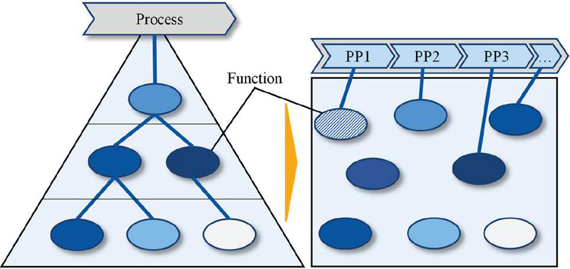
Figure 3 From hierarchical (left) to distributed systems (right) [13].
Due to their high force density, fluid power actuators are found across various industrial applications [22]. Therefore, it is crucial that the domain of fluid power is involved in the transformation towards I4.0-compliant systems [5]. Moreover, the possibility of arranging a plethora of fluid power elements into application-specific systems is a major advantage of this technology, which promotes the use of fluid power technology in manufacturing [23]. However, the heterogeneity of products and systems poses a domain-specific challenge for the digital transformation of the fluid power industry [23].
3 Reference Architectures and Interoperability
In the following chapter, reference architectures and interoperability are first introduced and placed in the context of fluid power.
3.1 Reference Architectures
Reference architectures aim to align companies regarding I4.0 and thus serve as a basis for implementing I4.0-concepts. Two essential representatives of reference architectures are the Reference Architecture Model Industrie 4.0 (RAMI 4.0) [24] by Plattform I4.0 and the Industrial Internet Reference Architecture (IIRA) [25] by the Industrial Internet Consortium [26].
RAMI I4.0 is a reference architecture for representing the I4.0-space subdivided into three dimensions [24]. These dimensions are the “Layers”, the “Life Cycle & Value Stream”, and the “Hierarchy Level”, see Figure 4. The layers, shown on the vertical axis, represent the different views of an asset. These views are intended to divide complex relationships concerning assets into relevant sub-aspects. As a result, the business, functional, information, communication, integration, and (physical) asset view is given. The second dimension is the product life cycle with its value chains, represented on the horizontal axis. This dimension distinguishes between type and instance assets according to the life cycle phase. The third dimension is the hierarchy level, allocating functionalities and responsibilities within the company. It is about a functional hierarchy, not the classes or hierarchy levels of the classic automation pyramid’s device [27]. In RAMI 4.0, assets are described via the Asset Administration Shell [24], which is introduced in Section 4.
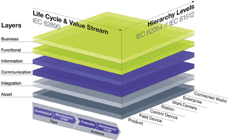
Figure 4 Reference architecture model Industrie 4.0 (RAMI 4.0) [24].
Another relevant reference architecture in the context of I4.0 is the Industrial Internet Reference Architecture (IIRA). Its goal is to enable industrial control systems to become internet-enabled, allowing them to seamlessly connect with individuals, information systems, corporate workflows, and IT-solutions for the purpose of data analysis [26].
According to [28], the IIRA focuses on different viewpoints (business, usage, functional, and implementation views) and provides models for each. The business viewpoint establishes the relationship between stakeholders’ concerns and their business goals, values, and intentions. Furthermore, the usage viewpoint outlines concerns related to the use of parts of an IIoT system. The functional viewpoint focuses on the functional components within an IIoT system, their relationships to each other, their structure, interfaces, and interactions, as well as the relationship and interaction of the system with external components that support or extend the overall system. Moreover, the implementation viewpoint covers the techniques necessary to implement the functional components, enable communication, and ensure processes. Within this hierarchical structure, decisions are made at higher levels and passed down to lower ones. Validation and revision of decisions are based on this process, starting from the subordinate levels. These viewpoints are arranged hierarchically, as shown in Figure 5.
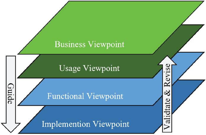
Figure 5 Industrial Internet Reference Architecture (IIRA) [25].
Different concepts for the real-time processing of data by an analytics framework are covered by IIRA [26]. RAMI 4.0, on the other hand, considers the mapping of an asset along its life cycle via the Asset Administration Shell [24]. In general, assets are all objects in physical or digital form in the custody of an organization and, accordingly, have a perceived value for that organization [29]. Mapping assets in digital form along their life cycle is an essential requirement for I4.0 in fluid power. Because of this, RAMI 4.0 is the widespread reference architecture model in fluid power [5]. This statement can be further supported by the fact that in the current state of the art, no approaches in fluid power based on other widespread reference architectures, such as, IIRA could be identified.
3.2 Interoperability and Standardization
In distributed systems, the subsystems depend on coordinating with each other through the transmission of messages [30]. When data is transmitted from one subsystem to another, unique syntactic and semantic rules must exist [31]. This concept is referred to as interoperability, which is described in [32] as a fundamental requirement for I4.0-systems. According to [33], interoperability is defined as the ability of two or more systems to access, exchange, and share information or data. It is based on agreements between requesters and providers on, for example, message-passing protocols, procedure names, error codes, and argument types [34].
In [35], interoperability is further categorized into seven levels, ranging from no interoperability to conceptual interoperability, as illustrated in Figure 6. The following level descriptions are based on this model:
The classification starts with level zero, with no connection between the systems and thus no interoperability. The next level is technical interoperability, where the systems are technically connected and can exchange data (e.g. with a network connection). Syntactic interoperability builds upon this, where data exchange is based on an agreed protocol. The meaning of the data is not specified at this level. The next level is semantic interoperability, where systems can exchange and analyse data semantically. As a result, semantic interoperability ensures that subsystems share a common understanding of data. Based on this is the level of pragmatic interoperability, where interoperating systems understand the context (system states and processes) and meaning of the exchanged data. At level five dynamic interoperability gets introduced, where the interoperating systems can realign the production and consumption of information based on the understood changes in meaning as the context changes over time. The final level is conceptual interoperability. At this level, there is full awareness of each other’s information, processes, contexts, and modeling assumptions [35].
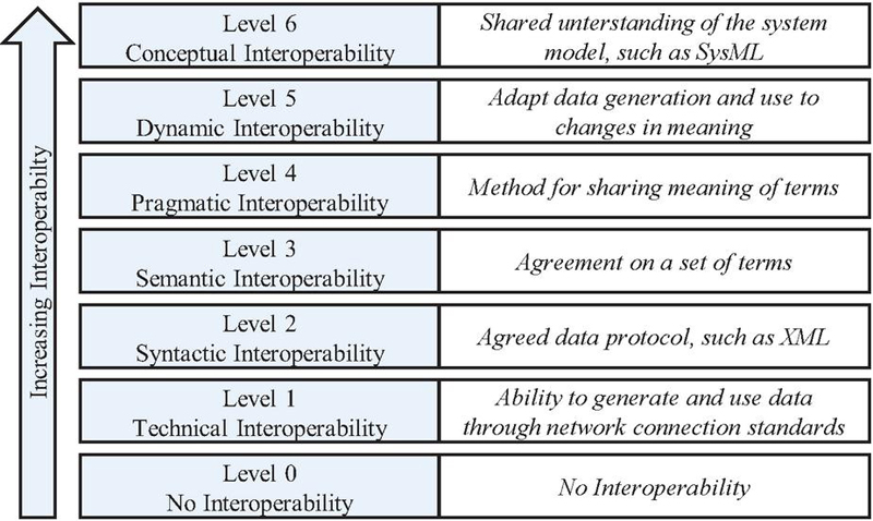
Figure 6 Levels of Interoperability [35].
Another model for describing interoperability was developed by Kubicek, who divides interoperability into four levels: technical, syntactic, semantic, and organizational interoperability [31].
As already pointed out, a standardized description of components is an essential prerequisite for achieving a high level of interoperability. Due to this, the properties of the components must be clearly defined to exchange information in the context of I4.0. To make this possible, there already are property dictionaries such as ECLASS. ECLASS is a reference standardization for the classification and detailed description of products and services to enable a semantic standard for I4.0 [36]. As an open standard, ECLASS is characterized above all by the fact that it is continuously developed further [36].
Based on the previous section, it becomes evident that a standardized description of components is fundamental for achieving interoperability in I4.0 environments. Semantically interoperable I4.0 use cases can be realized through the cross-stakeholder application of such standards (e.g., component manufacturers and system integrators). Consequently, this enables a shared understanding of the semantic description of an asset (e.g., a technical component). This semantic description is achieved through specifically defined properties.
Concerning fluid power, work has been underway since 2016 to standardize the properties of fluid power components [23]. As a result, relevant fluid power components, such as various types of pumps, valves, or cylinders, can already be described with properties via ECLASS [36]. For example, the semantic description of a hydraulic valve in ECLASS includes the properties “flow rate” and “hydraulic power” [36].
Further standardization activities in the field of fluid power can be found in the international standardization organization ISO. The most important fluid power ISO standardizations for I4.0 are ISO 5598 [37] and the ISO 18582 series [38, 39]. The relevance of these standards for I4.0 is discussed in [5]. To enable the most target-oriented standardization possible in fluid power, Fluid Power 4.0, an organization of the VDMA, is striving to synchronize ECLASS standardization with the ISO standards [23].
4 Virtual Representation and Interaction
In the context of I4.0, representations exist to describe objects in the virtual world. Relevant virtual representations are introduced below and placed in the context of fluid power. The interaction between digital representations then gets described.
4.1 Virtual Representation Through Digital Technologies
The modeling and exchange of information on physical assets have become very important in research and industry in recent years [40]. In this context, the term digital twin arises, with different meanings [40]. Using “twins” goes back to NASA’s Apollo program, where engineers were able to mirror space mission realities on earth during the mission [41]. NASA produced an identical physical twin of the spacecraft, used in space, on Earth in order to be able to simulate mission scenarios and thus make the most accurate possible predictions at any time, e.g., about component behavior [41]. In order to reduce the high resource requirements of a physical twin and also to be able to use it at earlier stages of development, digital twins were increasingly coined [42].
The term digital twin was first introduced in 2003 by Grieves, who described the digital twin as ideal concept for product life cycle management, which links physical elements to corresponding virtual elements through information flow [43]. In 2010 NASA describes the digital twin as a multi-physics simulation model of a technical system [44]. Thereafter, various definitions of this term emerged, of which most emphasized different aspects of a digital twin, depending on the respective user’s viewpoint (i.e., simulation, life cycle management, data services, etc.). Finally, since 2021, a broadly applicable definition for the field of manufacturing is given by the international standard ISO 23247-1 [45]. Therein, a digital twin in manufacturing is defined as “fit for purpose digital representation of an observable manufacturing element with synchronization between the element and its digital representation”, where an observable manufacturing element can be personnel, equipment, material, processes, facilities, environments, products, and supporting documents [45]. Given this definition, the Asset Administration Shell (AAS) can serve as a digital twin, while it additionally provides the possibility to also generalize virtual entities [40].
The AAS was developed in collaboration with the “Plattform Industrie 4.0” [46] and was first introduced in 2015 [47]. The AAS is a concept for digitally representing information and cross-stakeholder information exchange. The foundational framework of the AAS was subsequently published in DIN SPEC 91345 [24]. The Module Type Package (MTP) is a similar concept to the AAS. MTP originates from the working groups of NAMUR and ZVEI and aims to meet the future demand for modularized production in the process industry [46]. Therefore, there are two widespread concepts to meet the challenges according to I4.0. The concept of MTPs is tailored for the process industry and defines the submodels to be specified, which do not contain any instance-specific information. According to this, the AAS concept is much more generic. AASs are, in principle, not defined for any industry and, in addition to standardized submodels, can contain other submodels. Furthermore, the AAS allows types and instance-specific information, thus enabling a description of an asset along its entire lifecycle [20]. Since MTPs are mainly used in the process industry, and no approaches to MTPs in fluid power could be identified at the current stage, this concept will not be examined in greater depth.
Within the framework of I4.0, the concept of the I4.0 component was introduced. The I4.0 component comprises two parts: an asset and its corresponding AAS (see Figure 7) [24]. The AAS serves as a digital representation of the asset, for example a hydraulic pump, enabling Industry 4.0 compliant interaction [30]. The AAS includes submodels in which the asset is described in detail within a predefined context (e.g., for use case automated commissioning [30], or the use case simulation-based engineering [48]). To enable said exchange of data between systems, it is possible to distinctly identify the AAS, its descriptions, and the asset it’s based on using unique labels, such as Internationalized Resource Identifier (IRI) or International Registration Data Identifier (IRDI) [24].
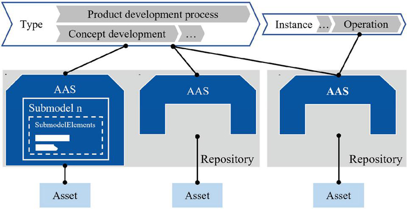
Figure 7 I4.0 component in the life cycle [24, 49].
Within an AAS, the characteristics of an asset are captured by SubmodelElements, which bundle various attributes such as properties or file [49]. These elements are thematically organized into submodels [29]. Submodels are published, for example, by the IDTA [50] as standardized templates, each of which describes the asset within a clearly specified use-case context. Accordingly, AASs can be archived within digital repositories, see Figure 7 [24]. In [51] a distinction is made between type assets and instance assets. A type asset defines the general, abstract concept of a product, component, or process and is usually established during the development phase. An instance asset, on the other hand, represents the concrete physical or digital realization of a type asset. In production, instance assets are created according to the specifications of their corresponding type asset and are associated with product-specific data, such as production, logistics, and testing information. Generally, a dependency exists between type and instance assets throughout their lifecycle, ensuring that modifications to the type asset are reflected in the instance asset. Nonetheless, an instance asset can also exist independently of a type asset.
4.2 Submodels
Standardized submodels are crucial for applying the AAS in industry and research. These enable a uniform description of the asset in the context of the respective sub-model, which provides the basis for I4.0-applications. There are currently numerous activities surrounding the standardization of submodels. Examples include the standardization efforts of the Industrial Digital Twin Association (IDTA) [50] and InterOpera [52].
The IDTA has already published numerous submodel templates for different applications, as shown in [50]. One example is the “IDTA 02006-3-0 Digital Nameplate for Industrial Equipment” submodel [53], in which product information can be stored as a digital datasheet. In practice, the digital nameplate can be accessed, for example, via a QR code scanner.
Another example is the “IDTA 02005-1-0 Provision of Simulation Models” submodel [54], which enables the mapping of simulation-related data to provide simulation models. This submodel enables access to simulation-related parameters, such as parameterization of simulation models.
In addition, InterOpera has already published numerous submodels. Examples are the submodel “Product Related Environmental Data,” which describes environmental data for the asset product, and “Facility Related Environmental Data”, which describes environmental data for the asset plant [52].
Moreover, submodels have already been designed in I4.0-based research projects, which are not standardized at present. These include, the submodel “Fluid” and the submodel “Topology” from the Plug-and-Produce project [55], which is presented in chapter 7.1.
4.3 I4.0-Compliant System Interaction Depending on the AAS
As pointed out in the previous chapters, AAS is the primary technology used in fluid power to represent assets digitally.
According to [29], three types of AAS can be distinguished based on their system interaction: passive, reactive, and proactive AAS (shown in Figure 8). Passive AAS are used for standardized data exchange between authorized actors. The AAS provides information about an asset in a standardized form. Data can be exchanged across all phases of the lifecycle. The reactive AAS has the same information content as the passive AAS. The difference to the passive AAS is that the inner structure is only accessible via an Application Programming Interface (API). In addition to information about the asset, the proactive AAS contains decision-making and optimization algorithms that ensure the intended autonomous behaviour of the I4.0 components. Using proactive AAS, decentral organized processes can be designed that build on a certain autonomy or decision-making capability of the AAS.
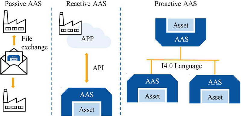
Figure 8 Three types of AAS [29].
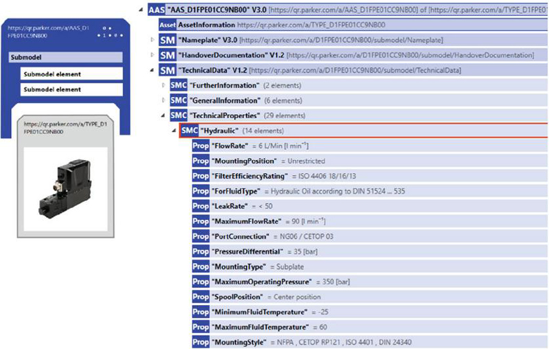
Figure 9 Exemplary Asset Administration Shell (AAS) of a Parker valve, taken from [56] and visualized using the AASX Package Explorer.
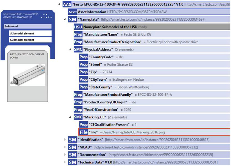
Figure 10 Exemplary AAS of a Festo pneumatic cylinder, taken from [57] and visualized using the AASX Package Explorer.
Examples of AAS in fluid power
The following presents a selection of AAS in fluid power, focusing on exemplary cases. The AAS are displayed in the AASX Package Explorer.1 Figure 10 shows an exemplary AAS for a Parker hydraulic valve. The AAS is shown with three submodels: “Nameplate”, “HandoverDocumentation”, and “TechnicalData”. These submodels are often further structured into SubmodelElementCollections (SMC), in which thematically related properties are grouped. For instance, the hydraulic properties of the valve are listed in the SMC “Hydraulic”, analogous to a hydraulic data sheet, including parameters such as spool position (“SpoolPosition”), flow rate (“FlowRate”), and maximum operating pressure (“MaximumOperatingPressure”). Another exemplary AAS is shown in Figure 10 for a Festo pneumatic cylinder. The contents of the submodel “Nameplate” are visible, which allow the storage of information such as the manufacturer’s name (“ManufacturerName”), the physical address (“PhysicalAddress”), and the CE marking (“Marking_CE”). The last example is shown in Figure 11 for a Bosch Rexroth hydraulic valve, where the submodel “TechnicalData”, the submodel “HandoverDocumentation” and the submodel “Nameplate” are displayed. Moreover, technical properties of the submodel “TechnicalData” are visible, for example, the weight (“Weight”), the size (“Size”), and the maximum flow rate (“Max_flow”) of the valve.
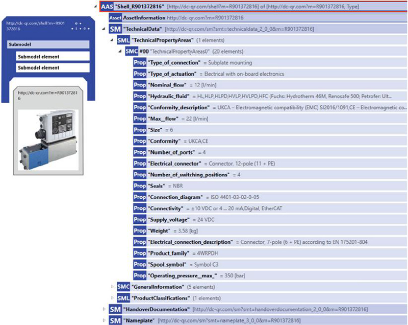
Figure 11 Exemplary AAS of a Bosch Rexroth valve is visualized using the AASX Package Explorer. The AAS is accessible in [58].
4.4 Communication Protocols
For the AAS to be able to interact with each other, standardized communication protocols are necessary. For this purpose, communication protocols such as OPC UA (Open Platform Communications Unified Architecture) and AutomationML (Automation Markup Language) are used in the context of I4.0 [59]. These two communication protocols are recommended in RAMI 4.0 for I4.0-applications considering AAS [27]. For this reason, OPC UA, as well as AutomationML, are presented below. For a description of other communication protocols, such as HTTP Rest [60], the relevant literature is referenced.
OPC UA is one of the most widely used communication standards for I4.0-applications [61]. On the one hand, OPC UA provides the communication infrastructure, and on the other hand, the basis for information modeling [62]. The standardized information modeling is based on the OPC UA metamodel. The concept of OPC UA is based on OPC UA servers and OPC UA clients interacting through services and executing on a hardware device called the host [21].
Each OPC UA client can access data of an OPC UA server. This access can only be done by knowing the specific information model the OPC UA server uses to represent the information. The semantics of the data objects are standardized via the information model, so OPC UA clients can rely on OPC UA servers using the same standardized information model to provide information in the same way. Clients can therefore interpret the semantics. As a result, OPC UA adds considerable value to the realization of vendor-independent interoperability. [63]
AutomationML is an open and neutral XML-based (Extensible Markup Language) data exchange format that can be used for product, process, and resource descriptions within the production-system engineering domain [64]. The format can systematically manage data exchange workflow between multi-disciplinary engineering tools [65]. AutomationML stores planning information using the object-oriented paradigm and allows physical and logical plant components to be modeled as data objects in which different aspects are encapsulated [66]. An object can consist of other sub-objects simultaneously as part of a larger composition or aggregation [66]. Furthermore, AutomationML combines existing industry data formats in its specifications developed to store and exchange various aspects of planning information [66].
The two communication protocols presented are merely a selection of existing communication protocols. A communication protocol suitable for I4.0 applications should meet specific requirements. These can include:
• High platform independence: Due to the industry’s heterogeneous interface environment, the communication protocol should be compatible with different interfaces. OPC UA enables use on different hardware and operating systems [67], and AutomationML enables mapping different data formats, which could be available in standardized and proprietary forms [68].
• Standardized communication protocol: The communication protocol should be standardized so that it is implemented and used in the same way by different stakeholders. This is the only way to enable interoperable use across stakeholders. OPC UA is standardized in DIN EN IEC 62541 [69] and AutomationML in DIN EN IEC 62714 [70].
• Enabling I4.0-applications: The communication protocol should enable I4.0-applications. Accordingly, OPC UA can be used, for example, for real-time data exchange between different machines. AutomationML is a suitable language for adequately describing products and processes and their relationships along the life cycle. In addition, there are already approaches to enable the interaction of AutomationML and OPC UA. Further information can be found, for example, in [71].
5 Implications for Fluid Power Components and Systems
Creating systems of I4.0 components brings new requirements and implications for fluid power components and systems. On one hand, the increasing integration of electronics into conventional components and systems forms one pillar of the digital transformation envisioned in the frame of I4.0. On the other hand, the trend of components with discretized functional elements, also termed digital hydraulics, plays into the development of flexible and decentralized fluid power systems. Miny et al. [72] present a classification of possible deployment variants based on the principle of independent usability. Deployment environments include integration into the AAS, mounting on a submodel server, standalone deployment, or coupling with assets. Submodels can be categorized as either passive (without execution logic) or active (with internal execution logic). Several requirements are outlined for effective interaction with submodels, including access protocols, information security, robustness and reliability, availability and reachability, time performance and response time, and discoverability. These requirements vary depending on specific use cases and scenarios.
5.1 Sensors
Sensors are one main group of electronic elements that experience an increasing application in fluid power. In the context of I4.0, sensors play a crucial role in facilitating the integration of advanced technologies into fluid power systems. They allow monitoring of key parameters such as pressure, temperature, flow rate, and fluid level. Therefore, sensors are indispensable for implementing advanced maintenance strategies such as condition-based monitoring and predictive maintenance or for performance tracking during operation [73]. In a broader sense, sensors encourage automation and autonomy and hence promote distributed production systems as envisioned in the frame of I4.0.
While traditionally, sensors are mainly included in fluid power applications as standalone components, they experience an increased integration into fluid power components. Accordingly, it is state of the art to have position transducers integrated into hydraulic cylinders [74, 75] and servo-valves [76, 77] or to have pumps equipped with pressure sensors [78, 79]. Moreover, as Figure 12 indicates, sensors themselves experience an evolution towards higher integration of electronics to provide connectivity and computing capabilities [73]. Accordingly, current research trends on sensors involve developing self-testing and self-calibrating capabilities of such smart sensors [80, 81], improving real-time capabilities and linking information acquired in the distributed sensor system to provide higher data quality and reliability [82].
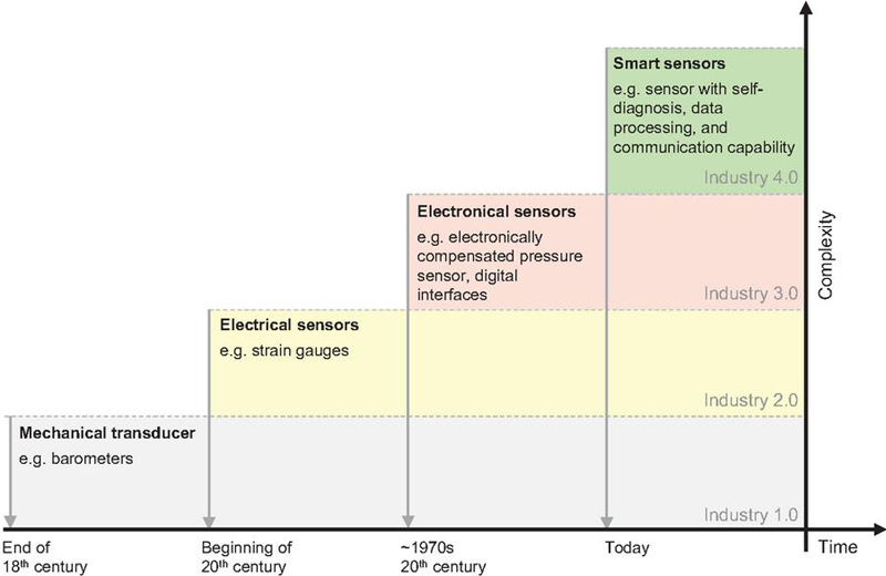
Figure 12 Historic evolution of sensors in the context of industrial revolutions [73].
5.2 Onboard Electronics and Devices
Given the aim to provide software-based functionalities to classical physical products, the need for computing power and memory arises. Therefore, several devices have been introduced to the market, and many fluid power components are equipped with onboard electronics. More specifically, the tasks to be solved by such electronics include:
• Improving functionality of fluid power components
• Providing computing power on the edge for digital services
• Enabling data aggregation, data transfer, and communication
Since the early 2000s, onboard electronics are commonly found in servo-valves [83–85]. This allowed manufacturers to deliver their valves with pre-parametrized digital controllers and parametrization, as well as diagnosis interfaces. As a result, the performance of modern control- and servo-valves could be increased. Furthermore, usability and interoperability of such valves are improved, as they are ready-to-use components, that require little to no adjustment effort by the operators. Similarly, digital pump controllers can increasingly be found to replace conventional analog pump controllers [86, 87]. The main benefit of digital controllers over hard-wired analog controllers, is their simpler reconfigurability, which also is in accordance with the I4.0 theme of CPS, whose functionality is modifiable on a software level.
Moreover, equipping fluid power components with electronics can be motivated by the need to provide computing power “on the edge”. Especially when data must be stored and processed on site, memory and processing units must be available. While some manufacturers integrate such electronics into their fluid power components [88, 89], dedicated devices can be found on the market which allow to add computing capabilities to conventional products [90]. Consequently, the available computing power can be used to add functionalities such as local data analyses or data compression.
For the transmission of data and general communication, modern fluid power products mainly offer digital fieldbus interfaces. In contrast to analog interfaces, digital interfaces promote decentralized network concepts in which network participants can exchange pre-processed top-level information instead of transmitting and processing raw data through a central computing instance. Common digital communication interfaces in modern fluid power products are CAN, Profibus, or EtherCAT. For communication across fieldbus technologies, some products provide an IO-Link interface [91].
The distribution of computing power and the efficient connectivity allow the grouping of fluid power components to form functional modules, which can interact with each other and with a centralized control module. This concept, often termed a connected multi-axis concept, aims at increasing the modularity, transparency, and controllability of fluid power drives [92].
Furthermore, several manufacturers in fluid power nowadays offer gateway devices that integrate conventional fluid power systems and components into the I4.0 world [93–95]. Simultaneously compatible with proprietary communication protocols, data structures, and modern I4.0 interfaces, existing fluid power systems can be adapted to an I4.0 infrastructure.
Introducing electronics into fluid power components adds various functionalities to conventional products. Moreover, it enables more autonomous operation of such components, allowing the composition of fluid power systems more efficiently, as only top-level commands have to be exchanged between system elements [96].
5.3 Software Platforms and Services
Cyber physical systems aim to add value to existing products by extending conventional physical components through virtual representations. This opens a new business area for software-based products. Possible software products can range from general frameworks for managing and exploiting the merits of cyber physical systems, up to specific software applications which provide specific functionalities.
Over the last two decades, several traditional companies in the field of hydraulics and pneumatics have extended their product portfolio of physical components with software products. Besides providing software for parametrization and control programming, the progress towards I4.0 triggered the emergence of various additional software products. Currently, a larger group of software provided by fluid power companies involves the acquisition, storage, and analysis of data [97–100]. Such software is mostly based on a cloud infrastructure, where during the operation of a component acquired data is stored, and made available to the component manufacturers. Consequently, the component manufacturers offer a variety of services for data analytics, such as condition and load monitoring or maintenance services.
Furthermore, the capability of I4.0 components and systems to self-consistently track and communicate operation data can serve as basis for disruptive business models, such as pay-per-use models. With pay-per-use models, operators of machines do not pay for the machine itself, but for the service it provides, i.e., the operation performed by it. A hardware concept and information model which promotes new digital business models is described in [101]. Commercial applications of pay-per-use models are given in [102, 103], for providing pressurized air and for the service of hydraulic pipe forming machines, respectively.
5.4 Digital Fluid Power
In addition to the virtual description of assets in the context of I4.0, the physical design of subsystems and components plays a central role in realizing I4.0-solutions. Breaking down subsystems to independently actuable functional elements allows higher functional flexibility of these subsystems. Moreover, defining a finite set of fundamental functional elements promotes a standardized description of fluid power components. Further, the function of a subsystem can be determined more strongly by the software used to control such subsystems.
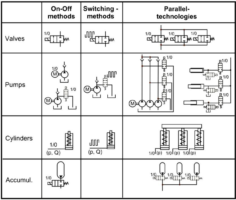
Figure 13 Classification of digital fluid power according to [104] and [105].
The field of digital fluid power provides an existing design paradigm, which offers the aforementioned desirable characteristics of I4.0-friendly fluid power systems [104]. The key property of digital fluid power systems is that they are solely controlled by “(…) discrete valued component(s) actively controlling system output” [105]. Practically speaking, respective systems are exclusively controlled by on-off valves which then make it possible to establish systems that switch between discrete states of the system. Figure 13 gives an overview on a classification of digital fluid power solutions and possible realizations.
Examples of commercial products which build upon this concept are the Festo Motion Terminal, which is a modular programmable valve terminal [106], or the Digital Displacement Pumps from Danfoss [107]. However, as the authors of [104] are pointing out, that fluid systems design ideally considers a wider set of aspects (e.g., costs), besides the compatibility concept of I4.0, so that the mentioned merits of digital fluid power have to be compared against other possible drawbacks.
6 Review of Asset Administration Shell within Scientific Research
After I4.0-related topics have been presented on a fundamental basis, an overview of research activities in the field of AAS is presented. AAS represents the central technology for data exchange in the context of I4.0. Since 2017 a total number of 186 scientific papers related to the AAS have been published. The papers can be classified into following 12 categories (see in Table 1):
Table 1 Research Categories of AAS Papers. Publication data were collected via Google Scholar up to August 3rd, 2025. The analysis was limited to articles with the terms “Asset Administration Shell” or “AAS” in the title. Abstracts were reviewed, and each article was categorized according to the 13 predefined thematic sections outlined below. Categories no. 8 to 13 do not have an abbreviation because they classified into “others” due to visual clearness
| Total Number | |||
| No. | Category | Abbreviation | of Publications |
| 1 | AAS Technology | AAS | 74 |
| 2 | Industrial & Manufacturing Engineering | I&M | 71 |
| 3 | Product & Application Lifecycle Management | P-&ALM | 24 |
| 4 | Fluid Power Systems | FPS | 12 |
| 5 | Model Development & Simulation | MD&S | 7 |
| 6 | (Chemical) Plant & Process Engineering | (C)P&P | 7 |
| 7 | Review | R | 4 |
| 8 | Environmental Engineering | – | 3 |
| 9 | (Renewable) Energy Technology | – | 2 |
| 10 | Automotive Engineering | – | 2 |
| 11 | Mechatronics & Robotics | – | 1 |
| 12 | Aerospace Engineering | – | 1 |
| 13 | Transportation & Infrastructural Engineering | – | 1 |
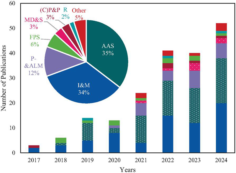
Figure 14 Number of publications of AAS papers from 2017 to 2024. The numbers of publications were retrieved from Google Scholar until August 3rd, 2025. As only complete calendar years were considered, the year 2025 was excluded from the analysis.
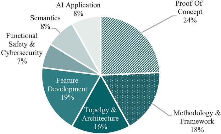
Figure 15 Total distribution of AAS-specific research topics. The numbers of publications were retrieved from Google Scholar until August 3rd, 2025.
Figure 15 shows the rapid development and interest in the topic of AAS. The first largest category is “AAS Technology”. This is an umbrella term, which includes different topics focusing on Proof-Of-Concept, Methodology & Framework, Topology & Architecture, Feature Development, Functional Safety & Cybersecurity, Semantics, and AI Applications of the Asset Administration Shell as such.
Compared to Figure 15, the total distribution of AAS topics is more balanced (see Figure 15). Between 2017 and 2024, most papers concentrated on the topic of “Proof-Of-Concept.” This category encompasses papers covering the vast advancements achieved by implementing AAS solutions for different practical use cases, like Siewert et al. [108].
Research topic “Proof-Of-Concept”
Siewert et al. [108] defined specialized submodels within the AAS to store necessary data for quality inspection and AR overlays. A prototype application for Microsoft HoloLens 2 using Eclipse BaSyx was developed, allowing technicians to receive real-time guidance during the inspection. The system consists of an AR client application on HoloLens 2 and a server component that includes an AAS registry and a fileserver for static content like 3D models. The AAS registry manages persistent storage, searching, and querying of AAS and submodels, using MongoDB as the backend. The AAS contains two submodels: “QualityControl” submodel, and “ARData” submodel. The first submodel stores all relevant Quality Inspection (QI) information, including tasks, steps, expected values, actual measured values, documentation details (e.g., technician name and timestamp), and tolerance information. The ”ARData” submodel contains visualization data required for AR overlays to guide technicians during inspections. The successful implementation of the solution results in the following process: First, technicians authenticate via QR codes linked to specific assets’ AAS. Upon scanning the QR code, the application retrieves associated “QualityControl” and “ARData” submodels from the registry. Finally, the AR application displays measurement prompts at correct spatial positions and target measurements to assist technicians effectively.
Research topic “Methodology & Framework”
Paper classified under the category “Methodology & Framework” are aiming to standardize the development and structure of AAS. One example is Bouter et al. [109]. The objective of this paper is to address the lack of established methodologies for identifying the necessary submodels required for specific use cases in I4.0, particularly focusing on immaterial assets. Bouter et al. propose a comprehensive methodology that starts with a functional description of use cases rather than relying solely on existing standards. The methodology consists of three main phases: knowledge representation of phase, I4.0-compliance phase, and evaluation phase.
The knowledge representation phase involves requirements analysis to derive functional requirements from use case descriptions. A conceptual model is developed using various formalization methods (e.g., UML, ER diagrams) and an intermediate review ensures that domain experts validate the conceptual model.
The I4.0-compliance phase adapts the conceptual model to align with AAS components and identifies necessary submodels based on functionalities. It emphasizes reusability of existing standards and submodels to enhance interoperability. The final evaluation phase validates that each designed submodel meets functional requirements through deployment in real-world scenarios and ensures that identified models effectively solve problems outlined in use case analyses.
Research topic “Topology & Architecture”
Paper classified under the category “Topology & Architecture” cover research optimizing the structure of AAS, like Miny et al. [72]. The paper investigates whether submodels can be designed independently, allowing for flexible physical deployment in computer networks or on information media, separate from their overarching AAS. Miny et al. present a classification of possible deployment variants based on the principle of independent usability. Deployment environments include integration into the AAS, mounting on a submodel server, standalone deployment, or coupling with assets. Furthermore, submodels can be categorized as either passive (without execution logic) or active (with internal execution logic). Several requirements for effective interaction with submodels are outlined, including access protocols, information security, robustness and reliability, availability and reachability, time performance and response time, and discoverability. These requirements vary depending on specific use cases and scenarios.
Three concrete usage scenarios are evaluated to illustrate how the classification is applied:
• Scenario 1: Engineering with Technical Data Submodel
• Scenario 2: Scheduling with Material Tracking Submodel
• Scenario 3: Machine Maintenance Control via Submodel
The first scenario focuses on providing technical data for component manufacturers during system design. The second scenario involves using a material tracking submodel within a Manufacturing Execution System (MES) to manage production processes. The final and third scenario details how maintenance staff interact with machine control interfaces through an AAS submodel. Finally, Miny et al. [72] recommend suitable deployment variants based on the requirements identified in each scenario and emphasize that, although many deployment combinations are theoretically possible, practical considerations will guide the choice toward more appropriate implementations.
7 Use Cases of Asset Administration Shell in Fluid Power Technology
Previously, the research activities within the AAS were presented. It was emphasized that there are already activities in this field of research in various areas. In this course, research activities in the field of AAS in fluid power were highlighted. These are first summarised below in Table 2 and then described in the context of higher-level use cases.
Table 2 List of Fluid-Power-System-related AAS publications. The numbers of publications were retrieved from Google Scholar until August 3rd, 2025
| Publication | Publication | |||
| Authors | Year | Type & Place | Topic | Use Case |
| Alt et al. [9] | 2018 | Conference / IFK | Fundamental challenges and opportunities of Industry 4.0 | Automated commissioning |
| Alt et al. [110] | 2018 | Conference / FPMC | Fundamental concept for “Plug-and-Produce” with the example of an Electro-Hydraulic Actuator | Automated commissioning |
| Alt and Schmitz [12] | 2019 | Conference / FPM | Introduction of the basic requirements for “Plug-and-Produce” | Automated commissioning |
| Alt et al. [111] | 2020 | Conference / IFK | Introduction of an AAS-based information model based on the example of a pneumatic handling system | Automated commissioning |
| Schweizer et al. [112] | 2020 | Conference / IFK | Enhancing Semantic Structures of AAS for implementation of “Plug-and-Produce” | Automated commissioning |
| Schweizer et al. [55] | 2021 | Journal / at – Automatisierungstechnik | Orchestration and choreography of commissioning processes based on the example of a pneumatic handling system | Automated commissioning |
| Stegmaier et al. [113] | 2022 | Conference / ETFA | Concept for efficient development of behaviour models in the context of digital twins | Others |
| Zhidchenko et al. [114] | 2022 | Journal / IEEE Access | Optimization of physics-based Digital Twins for heavy equipment machines | Others |
| Zhidchenko et al. [115] | 2023 | Conference / INDIN | Optimization of physics-based Digital Twins for heavy equipment machines | Others |
| Heppner et al. [116] | 2023 | Conference / ETFA | AAS Data Layer for the simulation-based engineering process | Simulation-based engineering |
| Becker et al. [117] | 2024 | Conference / FPMC | Overall Framework for parameterization of the system simulation based on AAS | Simulation-based engineering |
| Alt et al. [48] | 2024 | Conference / IFK | Integration of field and device data in the system simulation based on the example of a hydraulic press | Simulation-based engineering |
| Ritz et al. [118]1 | 2025 | Conference / SICFP | Overview of the potential of AAS to accelerate the product development process | Product development/ Simulation-based engineering |
| 1The cited publication was still in the publication process and not yet accessible at the time this manuscript was written. The author, as a co-author, was aware of its content and cited it accordingly. | ||||
The paper shown in Table 2 can be divided into the use case categories automated commissioning, simulation-based engineering and others, which are presented below.
7.1 Automated Commissioning
Commissioning is the phase of a machine life cycle in which various system components from different manufacturers interact with each other for the first time. As fluid power systems allow for high flexibility in terms of circuit design, the required commissioning steps can also vary drastically between different systems. Consequently, research on automated commissioning, e.g. in the context of service-oriented approaches, holds significant relevance. Accordingly, the use case of automated commissioning of fluid power systems through I4.0-concepts was thoroughly investigated in the work of Alt et al. [110, 111], Alt and Schmitz [12], Alt [30] and Schweizer et al. [55, 112]. These works build on one another to some extent.
Initial investigations of challenges and requirements for the application of I4.0-concepts in fluid power are presented in [9, 12]. In [111], Alt et al. demonstrate how a classical pneumatic handling system can be enhanced toward an IIoT system. Automated commissioning was examined using a pneumatic handling system for repositioning an object. The commissioning steps of the reference system were grouped into three pressure-dependent categories: unpressurized, low pressure and operating pressure, to ensure safe execution. In this way, the system pressure is only increased once safety-critical steps have been successfully completed.
For the implementation of an I4.0-based commissioning framework, Schweizer et al. [55] describe the design of the employed AAS as well as the orchestration and choreography of the commissioning process. In the respective work, orchestration has been defined as the order of commissioning steps an I4.0 component must undergo, while the coordination between individual components is termed choreography. An information model based on the proactive AAS and Business to Manufacturing Markup Language (B2MML) was found suitable for orchestrating the commissioning steps in distributed automation systems. For this purpose, individual fluid power components are provided with proactive AASs that realize autonomous and cooperative commissioning among each other.
In the course of this research, numerous submodels were developed [30]. For all components (e.g, hydraulic components) relevant to the commissioning process, corresponding I4.0 components were created. Each AAS stores the steps required for its orchestration as information in its respective submodel Plug-and-Produce (SMPnP). Furthermore, the submodel Fluid (SMFluid) provides access to relevant fluid power properties (e.g., cylinder diameter or pump flow rate), which are modeled as SubmodelElements. In this context, ECLASS properties were used where available to ensure semantic clarity. To encapsulate manufacturer-specific properties and functions, the submodel Proprietary Functionality (SMPropF) was created. This submodel forms the interface from heterogeneous and proprietary to interoperable systems. In addition, the submodel implements a proxy for controlling the respective I4.0 components. Furthermore, the submodel Topology (SMTopo) was developed. Within this submodel, the fluidic topology (TOPFluid) describes the fluid power network and the direction of energy flow, the structural topology (TOPStruct) represents the mechanical and packaging-related arrangement of components, and the functional topology (TOPFunct) captures how system assets are functionally interconnected. The last submodel developed is the Submodel Communication (SMCom). It ensures that I4.0 components can communicate with each other via various protocols, messages, and channels, providing a dedicated interface that enables flexible and transparent communication by encapsulating the communication type behind standardized properties and offering access control to the asset. These submodels were developed within the framework of the presented research for the use case of automated commissioning, but they were not standardized as templates by, e.g., the IDTA. An overview of the developed I4.0 component, including the developed submodels of the AAS, is shown in Figure 16.
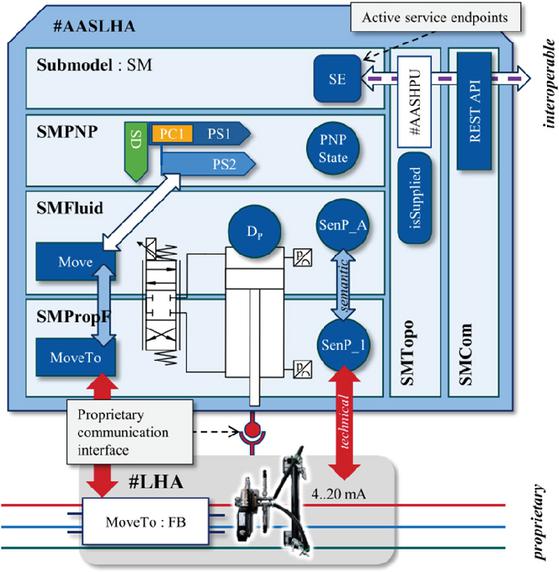
Figure 16 Structural overview of the fluid power I4.0 component, developed for the use case automated commissioning [30].
In [30] it was conclusively demonstrated that an I4.0 framework can automate or semi-automate the commissioning process, reducing both the time and effort required for manual activities. The validated reference system further showed that such an approach improves safety and repeatability while decreasing dependence on the commissioning engineer’s expertise. However, full automation of all commissioning steps was not possible for the reference system, as adjusting the end cushioning of pneumatic cylinders or commissioning throttle check valves still requires manual actions because these components lack suitable actuators.
7.2 Simulation-based Engineering
Simulation offers significant potential for automating parameterization, model integration and related processes, making this use case highly relevant and promising substantial improvements through the application of I4.0-concepts. Accordingly, the use case of simulation-based engineering of fluid power systems using I4.0-concepts was extensively examined by Alt et al. [48], Becker et al. [117] and Heppner et al. [116] within the context of fluid power. These works build on one another to some extent. The use case was carried out as part of the BaSys4FluidSim project, which aimed to develop a simulation framework for fluid power components for integrated and seamless engineering [117]. In this course, component data and simulation models were linked along the product life cycle to improve the simulation-based development process [117]. The AAS is used to provide fluid power component data and encapsulated simulation models [117]. In this context, the submodel “Generic Frame for Technical Data for Industrial Equipment in Manufacturing” [49] was used to provide component data for enabling a semantic search and parametrization of simulation models. Moreover, the submodel “Provision of Simulation Models” [54] was used to provide simulation models in the form of Functional Mock-up Units (FMUs) [48]. Furthermore, the developed framework comprises three functionalities aimed at improving the simulation-based development process using AAS [117]. An overview of the framework is presented in Figure 17.
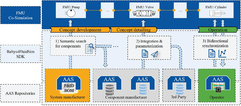
Figure 17 Simulation-based AAS Framework [117].
The three functionalities are conceptually outlined in [117] and implemented in the developed BaSys4Fluidsim SDK, which is based on the Eclipse BaSyx Python SDK2 [48, 116]. The first functionality makes it possible to search for and find component data or component simulation models from repositories of relevant stakeholders (e.g., component manufacturers, third party providers). The second functionality enables the domain- and tool-independent integration of simulation models into a simulation environment through the automatic parameterization of these models or the direct integration of functional mock-up units (FMUs). Moreover, [117] discusses interface designs of FMUs in lumped-parameter system simulations from a practical perspective, while [48] presents a concept for instantiation in which an AAS instance is created for each simulation model file to encapsulate the relevant parameters. The third functionality enables bidirectional synchronization between field devices and simulation models [117]. In addition to the described use case, Ritz et al. [118] provide an overview of the AAS and discusses its potential to accelerate product development.
7.3 Others
There are also other research activities that at least name or discuss the AAS from the concept. These include the work of Zhidchenko et al. [114, 115] and Stegmeier et al. [113].
8 Industry 4.0 in Fluid Power: Are We on Track?
In this section, the state of I4.0 in fluid power is reflected. For this purpose, the contribution by Haack and Meißelbach [3] will be referenced, in which it was clarified whether fluid power was on track in 2018 regarding I4.0. At that time, activities in the field of I4.0 had already begun. However, they were not yet advanced in various areas, such as the digital connectivity of hydraulic components and the information technology modelling of data. In general, the implementation of I4.0-concepts was more advanced in the electrical engineering sector than in the fluid power sector. Even though the direct comparison to other industries is not part of this research work, it can be concluded in the context that the progress of implementing I4.0-concepts in fluid power has improved.
In the context of information technology modeling, various activities have taken place since 2018. As a result, various submodels for the AAS have been created, which describe content-related or functional aspects of an asset in application-specific contexts [119]. Here, the standardization activities for submodels of the IDTA are particularly noteworthy. Furthermore, standardization activities regarding the semantic description of properties for fluid power components have been significantly advanced. As a result, numerous characteristics for fluid power components have now been standardized via ECLASS. This enables, for example, a digital description of fluid power components in the AAS, analogous to a technical data sheet. Even though the status does not yet allow a comprehensive description of all relevant fluid power components, there has been significant progress.
There is also vivid industrial and research activity in fluid power components and system implementations. As a result, the manufacturer portfolio has expanded towards smart I4.0-compliant products, as illustrated in the previous chapter. This is an essential step for fluid power, considering that in 2018, over 80 % of hydraulic components did not have digital connectivity [3].
Furthermore, there has been significant progress in implementing practical use cases in the context of I4.0. As a result, the use case of automated commissioning was researched and validated on two reference systems. Currently, there are further research activities in simulation-based development according to the automatic parameterization and integration of simulation models, which have been conceptionally shown in the context of this contribution.
As already mentioned, the comparison to other industries is not within the scope of this research. Regarding fluid power, however, there has been a significant increase in the implementation of I4.0-concepts since 2018. Initial applications of I4.0-concepts, such as the automated commissioning of fluid power systems and the parameterization of simulation models, were demonstrated in research projects.
To place these developments into a broader context, it is useful to consider how comparable digital transformation initiatives, similar to the German “Industrie 4.0”, are being pursued in other parts of the world. While this contribution focuses on fluid power in Germany, reviewing international strategies helps to understand common goals, diverse approaches, and shared challenges in implementing I4.0-concepts across national and industrial boundaries. Therefore, the following section outlines selected national programmes and strategic frameworks, sorted by continents, which reflect international efforts toward digitally integrated and intelligent manufacturing systems.
Europe
Similar to Germany, various national programs from different European countries have emerged, such as, “La Nouvelle France Industrielle” (France) [120], “Fabbrica Intelligente” [121] and “Piano Nazionale Industria 4.0” (Italy) [122], “Future of Manufacturing” and “National Innovation Plan” (UK) [123], “Smart Industry” and “Made in Sweden 2030” (Sweden) [124], and “Made Different” and “Digital Belgium” (Belgium) [125]. These programs all align in scope with Germany’s initiative, being funded and organized through public-private partnerships focused on smart manufacturing adoption.
North America
The Advanced Manufacturing Partnership from the US (AMP, launched in 2011, AMP 2.0 in 2013) aimed to integrate federal government, industry and academia into innovation ecosystems resembling I4.0-frameworks [126]. The Industrie 2030 initiative, launched jointly by the Canadian Manufacturers & Exporters (CME) and governmental bodies, set targets to double manufacturing sector value-added by 2030 and included smart technologies and digital transformation roadmapping [127]. Mexico has established itself as a globally recognized manufacturing location, primarily due to its cost competitiveness based on a relatively low-cost labor force and high-volume production capacities. Approximately half of the country’s exports are attributed to manufactured goods, with a substantial share representing technologically advanced products. To expand its positioning beyond cost advantages and to outline a long-term strategic vision for the manufacturing sector, the Mexican Ministry of Economy introduced a national roadmap in April 2016 titled Crafting the Future. This initiative aims to identify new development opportunities and strengthen technological and innovation capabilities within the country’s industrial landscape. [128]
South America
In Brazil, digital transformation in manufacturing is still at a preliminary stage. Stradioto and Frazzon (2023) report that although the theoretical discourse on Industry 4.0 is well developed, many firms face significant implementation gaps, demonstrating limited uptake of cyber-physical systems and integrated digital processes. [129]
Complementing this, a survey by Baio Junior and Carrer (2022) among small- and medium-sized metallurgical manufacturers in São Paulo shows selective adoption: cloud computing was used in 10 of 30 firms, horizontal and vertical systems integration in 5 firms, and both big data and IoT solutions in a smaller number of cases. [129]
Asia & Ocenia
China announced “Made in China 2025” and “Internet Plus” as part of its five-year planning post-2025 to transition to higher-value smart manufacturing and CPS adoption akin to I4.0 [130]. Japan adopted Super Smart Society (“Society 5.0”) under the Fifth Science and Technology Basic Plan in 2016, positioning CPS integration into broader societal and manufacturing systems [131]. Since 2014, South Korea is operating a national smart factory initiative under its “Innovation in Manufacturing 3.0” strategy, with reported deployment across 1,240 SMEs by early 2016, yielding productivity and defect reductions (e.g. -27.6% defects) [130]. Australia established a Digital Transformation Agency and an “Industry 4.0 Taskforce” in 2016, collaborating with German and U.S. counterparts in policy and standards alignment [132]. Malaysia launched Industry4WRD in 2018, a national roadmap promoted by the Ministry of International Trade and Industry, focusing on infrastructure, workforce digitization, and smart manufacturing [133].
Other Regions
Emerging economies such as those in Africa, the Middle East, and Southeast Asia currently display pilot or sector specific digital manufacturing efforts, notably in oil and gas or process industries, but have fewer formal Industry 4.0 branded national strategies, and the published literature remains sparse [134].
9 Conclusion
This contribution gives an overview of the state of the art of I4.0-research in fluid power. First, I4.0 was introduced, and aspects of I4.0 were placed in the context of fluid power. It was shown that existing virtual concepts in fluid power are based on RAMI 4.0 and, thus, on the AAS [24, 30]. It was then possible to show that, in addition to establishing virtual concepts, the physical components of fluid power have also drastically changed. More rudimentary fluid power components have become I4.0-compliant components with communication interfaces, that can fulfil additional services. As a result, it was highlighted that fluid power has already responded to the requirements of I4.0.
Furthermore, implementing I4.0-concepts in fluid power has improved significantly since 2018. Due to this, and alongside other important developments in this area in industry and research, extensive research activities have been carried out in the fields of automation commissioning and simulation-based engineering. Despite this, the currently achieved progress needs to be furthered so that fluid power can transition to I4.0-compliant systems. Firstly, it is necessary to further the standardization of properties so that fluid power components can be described semantically to the full extent. In addition, methods must be developed for companies to integrate these standards into their database with little effort. At the same time, investigating additional use cases is necessary to demonstrate and validate the direct benefits of I4.0-concepts. Relevant use cases that should be investigated in the context of fluid power are, for example, the topics of sustainability in terms of circular economy and carbon footprint. In these use cases, over the entire product life cycle large amounts of data are generated, which need to be processed, made available, and adapted in the event of changes. AAS is a promising technology in this respect. Looking into the field of electrical engineering, efforts are already being made, for example, as part of the automated calculation of the product carbon footprint of an electrical enclosure with components from different manufacturers [49].
In conclusion, this contribution has addressed the research question posed in the introduction: to what extent has fluid power research and industry progressed in implementing the concepts and objectives associated with the vision of Industry 4.0? The analysis shows that significant advancements have been made in both virtual and physical components of fluid power, moving the technology closer to I4.0-compliant systems. Therefore, many activities in terms of I4.0 have started or investigated, both in industry and academia. At the same time, it becomes evident that further standardization of component and system descriptions, the development of submodels for new use cases, the development of interfaces to integrate AAS frameworks into tool environments (e.g., Computer-Aided Engineering tools) along the product life cycle, and the demonstration of practical applications are essential to fully demonstrate and leverage the potential of I4.0.
References
[1] Plattform Industrie 4.0, “Leitbild 2030 für Industrie 4.0: Digitale Ökosysteme global gestalten,” 2019.
[2] Plattform Industrie 4.0, “Industrie 4.0: Auf dem Weg zur intelligent vernetzten Industrie,” 2023.
[3] S. Haack and A. Meißelbach, “Industrial Hydraulics – Are we really on track concerning Industry 4.0,” in 11th International Fluid Power Conference: 19th-21st of March 2018, Aachen, Germany, H. Murrenhoff, Ed., Aachen: RWTH Aachen University, 2018.
[4] V. Ritschl, R. Weigl, and T. Stamm, Wissenschaftliches Arbeiten und Schreiben. Berlin, Heidelberg: Springer Berlin Heidelberg, 2023.
[5] VDMA Fluid Power, “Fluid Power 4.0: digitize, connect, communicate,” 2019.
[6] H. Klagermann, W.-D. Lukas, and W. Wahlster, “Industrie 4.0: Mit dem Internet der Dinge auf dem Weg zur 4. industriellen Revolution,” VDI Nachrichten, no. 13, 2011.
[7] acatech – National academy of science and engineering, Recommendations for implementing the strategic initiative INDUSTRIE 4.0: Final report of the Industrie 4.0 Working Group, 2013.
[8] T. Miny et al., “Semi-Automatic Testing of Data-Focused Software Development Kits for Industrie 4.0,” in 2022 IEEE 20th International Conference on Industrial Informatics (INDIN), Perth, Australia, 2022, pp. 269–274.
[9] R. Alt, H. Murrenhoff, and K. Schmitz, “A survey of “Industrie 4.0” in the field of Fluid Power – challenges and opportunities by the example of field device integration,” The 11th International Fluid Power Conference, 11. IFK, March 19-21, 2018, Aachen, Germany, 2018.
[10] acatech – Deutsche Akademie der Technikwissenschaften, Kompetenzen für Industrie 4.0: Qualifizierungsbedarfe und Lösungsansätze, 2016.
[11] acatech – National academy of science and engineering, “SMART SERVICE WELT: Recommendations for the Strategic Initiative Web-based Services for Businesses. Final Report,” 2015.
[12] R. Alt and K. Schmitz, “Basic requirements for Plug-and-Produce of 14.0 fluid power systems,” in 2019 IEEE 8th International Conference on Fluid Power and Mechatronics (FPM), Wuhan, China, 2019, pp. 1440–1448.
[13] Verein Deutscher Ingenieure e.V. – VDI/ VDE-Gesellschaft Mess- und Automatisierungstechnik, Cyber-Physical Systems: Chancen und Nutzen aus Sicht der Automation, 2013.
[14] T. Bauernhansl, Ed., Industrie 4.0 in Produktion, Automatisierung und Logistik: Anwendung, Technologien, Migration. Wiesbaden: Springer Vieweg, 2014.
[15] M. P. Papazoglou and W.-J. van den Heuvel, “Service oriented architectures: approaches, technologies and research issues,” The VLDB Journal, vol. 16, no. 3, pp. 389–415, 2007, doi: 10.1007/s00778-007-0044-3.
[16] OASIS, “Reference Model for Service Oriented Architecture 1.0: Committee Specification 1, 2 August 2006,” 2006.
[17] S. Hüttenrauch et al., Fundamentals of Service-Oriented Engineering. Potsdam: Universitätsverlag Potsdam, 2006.
[18] Nicolai M. Josuttis, SOA in Practice: The Art of Distributed System Design. Beijing, Cambridge, Farnham, Köln, Paris, Sebastopol, Taipei, Tokyo: O’REILLY, 2007.
[19] I. Melzer, Service-orientierte Architekturen mit Web Services: Konzepte – Standards – Praxis, 4th ed.: Spektrum – Akademischer Verlag, 2010.
[20] M. Freund, A. Kehl, C. Barth, and C. Stich, “Das Module Type Package und die Verwaltungsschale – ein Ansatz zur Integration,” in Automation 2020: VDI Verlag, 2020, pp. 455–468.
[21] H. Baumgartel and R. Verbeet, “Service and Agent based System Architectures for Industrie 4.0 Systems,” in NOMS 2020 – 2020 IEEE/IFIP Network Operations and Management Symposium, Budapest, Hungary, 2020, pp. 1–6.
[22] K. Schmitz, Fluidtechnik – Systeme und Komponenten, 1st ed.: Shaker Verlag, 2021.
[23] VDMA Fluidtechnik, Fluidtechnik 4.0. [Online]. Available: https://fluidtechnik40.de/ (accessed: Jan. 13 2023).
[24] DIN SPEC 91345: Referenzarchitekturmodell Industrie 4.0 (RAMI4.0), DIN SPEC 91345:2016, DIN Deutsches Institut für Normung e. V., 2016.
[25] S.-W. Lin, “Industrial Internet Reference Architecture (IIRA),” 2015.
[26] C. Weber, M. Wieland, and P. Reimann, “Konzepte zur Datenverarbeitung in Referenzarchitekturen für Industrie 4.0,” Datenbank Spektrum, vol. 18, no. 1, pp. 39–50, 2018, doi: 10.1007/s13222-018-0275-z.
[27] VDI/ VDE-Gesellschaft Mess- und Automatisierungstechnik, Referenzarchitekturmodell Industrie 4.0 (RAMI4.0): Statusbericht, 2015.
[28] D. Young, The Industrial Internet Reference Architecture: Version 1.10. An Industry IoT Consortium Foundational Document, 2022.
[29] Plattform Industrie 4.0 and ZVEI, Details of the Asset Administration Shell – Part 2 (1.0RC01): Part 2 – Interoperability at Runtime – Exchanging Information via Application Programming Interfaces, 2022.
[30] R. Alt, “Service-Oriented Architecture for Automated Commissioning of Fluid Power Systems,” Dissertation, RWTH Aachen University, Aachen, 2023.
[31] H. Kubicek, A. Breiter, and J. Jarke, “Daten, Metadaten, Interoperabilität,” in Handbuch Digitalisierung in Staat und Verwaltung, T. Klenk, F. Nullmeier, and G. Wewer, Eds., Wiesbaden: Springer Fachmedien Wiesbaden, 2019, pp. 1–13. Accessed: 2019.
[32] T. Schröder and C. Diedrich, “Systemarchitektur für die Implementierung proaktiver Verwaltungsschalen auf Basis kognitionswissenschaftlicher Konzepte,” at – Automatisierungstechnik, vol. 67, no. 7, pp. 599–616, 2019, doi: 10.1515/auto-2019-0030.
[33] M. L. Zeng, “Interoperability,” Knowledge Organization, 46(2), pp. 122–146, 2019, doi: 10.5771/0943-7444-2019-2-122.
[34] S. Heiler, “Semantic interoperability,” ACM Computing Surveys, vol. 27, no. 2, 1995.
[35] W. Wang, “The Levels of Conceptual Interoperability Model: Applying Systems Engineering Principles to M&S,” Proceedings of Spring Simulation Multiconference (SpringSim’09), 2009.
[36] ECLASS e.V. [Online]. Available: https://eclass.eu/ (accessed: Jan. 27 2023).
[37] Deutsches Institut für Normung (DIN), DIN ISO 5598-Fluidtechnik -Vokabular (ISO/DIS 5598:2004): Standard consists of different parts published in the period from 2015 to 2021, 2004.
[38] Fluid power – Specification of reference dictionary. Part 1: General overview on organization and structure, 18582-1, International Organization for Standardization (ISO), 2016.
[39] Fluid power – Specification of reference dictionary. Part 2: Definitions of classes and properties of pneumatics, 18582-2, International Organization for Standardization (ISO), 2018.
[40] T. H. Miny, “Konzept für die semantische Interoperabilität zwischen Informationsmodellen,” Dissertation, RWTH Aachen.
[41] S. Boschert and R. Rosen, “Digital Twin – The Simulation Aspect,” Mechatronic Futures, pp. 59–74, 2016.
[42] R. Rosen, G. von Wichert, G. Lo, and K. D. Bettenhausen, “About The Importance of Autonomy and Digital Twins for the Future of Manufacturing,” IFAC-PapersOnLine, vol. 48, no. 3, pp. 567–572, 2015, doi: 10.1016/j.ifacol.2015.06.141.
[43] M. Grieves and J. Vickers, “Digital Twin: Mitigating Unpredictable, Undesirable Emergent Behavior in Complex Systems,” in Transdisciplinary perspectives on complex systems: New findings and approaches, F.-J. Kahlen, S. Flumerfelt, and A. C. Alves, Eds., Cham: Springer, 2016, pp. 85–113.
[44] M. Shafto et al., “Modeling, Simulation, Information Technology and Processing Roadmap: Technology Area 11,” Nov. 2010.
[45] ISO 23247-1: Automation systems and integration – Digital twin framework for manufacturing. Part 1: Overview and general principles, International Organization for Standardization (ISO), 2021.
[46] S. Grüner et al., “Integration von Module Type Package und Industrie 4.0 Verwaltungsschale,” Automation, 2021, doi: 10.51202/9783181023921-421.
[47] BITKOM, VDMA, and ZVEI, “Umsetzungsstrategie Industrie 4.0: Ergebnisbericht der Plattform Industrie 4.0,” 2015.
[48] R. Alt et al., “Seamless Integration of Device and Field Data into the System Simulation of a Hydraulic Servo-Press Using AAS,” in Proceedings of the 14th International Fluid Power Conference (IFK 2024), J. Weber, Ed., Aalborg: River Publishers, 2024, pp. 241–257.
[49] Plattform Industrie 4.0 and ZVEI, “SPECIFICATION. Submodel Templates of the Asset Administration Shell: Generic Frame for Technical Data for Industrial Equipment in Manufacturing (Version 1.1),” 2020.
[50] IDTA – Industrial Digital Twin Association e. V., Homepage of IDTA. [Online]. Available: https://industrialdigitaltwin.org/ (accessed: Sep. 8 2025).
[51] IDTA – Industrial Digital Twin Association e. V., “Asset Administration Shell Specification – Part 1: Metamodel Schema: Specification: IDTA Number: 01001-3-0,” 2023.
[52] Steinbeis EU for You der Steinbeis Innovation gGmbH, Interopera. [Online]. Available: www.interopera.de (accessed: Oct. 25 2023).
[53] IDTA – Industrial Digital Twin Association e. V., IDTA 02006-3-0 Digital Nameplate for Industrial Equipment: Submodel Template of the Asset Administration Shell. [Online]. Available: https://industrialdigitaltwin.org/en/use-cases/digital-nameplate-one-scan-saves-countless-resources (accessed: Jan. 13 2023).
[54] IDTA – Industrial Digital Twin Association e. V., “IDTA 02005-1-0 Provision of Simulation Models: Submodel Template of the Asset Administration Shell,” 2022.
[55] H. Schweizer, N. Braunisch, R. Alt, K. Schmitz, and M. Wollschlaeger, “Prozesskomposition in verteilten Automatisierungssystemen,” at – Automatisierungstechnik, vol. 69, no. 3, pp. 242–255, 2021, doi: 10.1515/auto-2020-0118.
[56] Parker Hannifin Corporation, D1FPE01FC9NB0050. [Online]. Available: https://qr.parker.com/a/1RABNX7M (accessed: Feb. 11 2025).
[57] Industrial Digital Twin Association e.V.: Samples for Asset Administration Shell (AAS): aasx-package-explorer (English). [Online]. Available: https://admin-shell-io.com/samples/ (accessed: Aug. 18 2025).
[58] Bosch Rexroth AG, Digital Service Assistant. [Online]. Available: https://www.boschrexroth.com/de/de/service-und-support/service/digital-service-assistant/ (accessed: 21.10.2025).
[59] Plattform Industrie 4.0, Details of the Asset Administration Shell: The exchange of information between partners in the value chain of Industrie 4.0 (Version 3.0RC02), 2022.
[60] A. Yates, K. Beal, and S. Keenan, “The Ensembl REST API: Ensembl Data for Any Language,” BIOINFORMATICS, vol. 31, no. 1, pp. 143–145, 2015.
[61] R. Schiekofer, S. Grimm, M. M. Brandt, and M. Weyrich, “A formal mapping between OPC UA and the Semantic Web,” in 2019 IEEE 17th International Conference on Industrial Informatics (INDIN), Helsinki, Finland, 2019, pp. 33–40.
[62] W. Mahnke, “Informationsmodellierung mit OPC Unified Architecture,” atp magazin, vol. 62, p. 58, 2020, doi: 10.17560/atp.v62i3.2455.
[63] U. Ernste and W. Mahnke, “OPC Unified Architecture,” at – Automatisierungstechnik, vol. 59, pp. 397–404, 2011, doi: 10.3403/BSENIEC62541.
[64] AutomationML. [Online]. Available: https://www.automationml.org/about-automationml/automationml/ (accessed: Jan. 13 2023).
[65] X. Ye and S. H. Hong, “An AutomationML/OPC UA-based Industry 4.0 Solution for a Manufacturing System,” in 2018 IEEE 23rd International Conference on Emerging Technologies and Factory Automation (ETFA), Turin, 2018, pp. 543–550.
[66] R. Drath, A. Luder, J. Peschke, and L. Hundt, “AutomationML – the glue for seamless automation engineering,” International Conference on Emerging Technologies and Factory Automation (ETFA), pp. 616–623, 2008, doi: 10.1109/ETFA.2008.4638461.
[67] OPC Foundation, The Industrial Interoperability Standard. [Online]. Available: https://opcfoundation.org/about/opc-technologies/opc-ua/ (accessed: Oct. 25 2023).
[68] R. Drath, A. Fay, and M. Barth, “Interoperabilität von Engineering-Werkzeugen: Konzepte und Empfehlungen für den Datenaustausch zwischen Engineering-Werkzeugen,” at – Automatisierungstechnik, vol. 59, 2011.
[69] Deutsches Institut für Normung (DIN), DIN EN IEC 62541 – OPC Unified Architecture: Standard consists of different parts published in 2015 and 2021.
[70] Deutsches Institut für Normung (DIN), DIN EN IEC 62714: Engineering data exchange format for use in industrial automation systems engineering – Automation markup language, Standard consists of different parts published in the period from 2015 to 2023.
[71] R. Henßen and M. Schleipen, “Interoperability between OPC UA and AutomationML,” Procedia CIRP, vol. 25, pp. 297–304, 2014, doi: 10.1016/j.procir.2014.10.042.
[72] T. Miny, M. Thies, T. Kleinert, and J. Vogel, “Deployment of Asset Administration Shell Submodels,” in 2024 IEEE 29th International Conference on Emerging Technologies and Factory Automation (ETFA), Padova, Italy, 2024, pp. 1–8.
[73] A. Schütze, N. Helwig, and T. Schneider, “Sensors 4.0 – smart sensors and measurement technology enable Industry 4.0,” J. Sens. Sens. Syst., vol. 7, no. 1, pp. 359–371, 2018, doi: 10.5194/jsss-7-359-2018.
[74] Parker Hannifin Corporation, “HMIX Hydraulic Cylinders with Integrated Transducers,” (Revision: HY07-1175/UK POD 03/2013 ZZ), 2013.
[75] Festo AG & Co. KG, “Standard cylinders DNCI to ISO 6431 with integrated displacement encoder,” (Revision: 210405), 2005.
[76] Bosch Rexroth AG, “Directional control valves, direct operated, Directional control valves, direct operated, with electrical position feedback and integrated electronics (OBE),” (Revision: 29121/08.2022), 2019.
[77] Argo Hytos, “Proportional Directional Control Valve, with Digital Onboard Electronics and Internal Feedback PRM9-06,” (Revision: PRM9-06_5129_3en_05/2019), 2019.
[78] Parker Hannifin Corporation, This is setting new standards: New Electronic Control eP2/eP3, 2018.
[79] Bosch Rexroth AG, “Axial piston variable pump A4VSO Series 1x and 3x,” (Revision: RE 92050/10.2018), 2018.
[80] T. Kramer and J. Weber, “Self-Sensing Design of Proportional Solenoids,” in BATH/ASME 2020 Symposium on Fluid Power and Motion Control, Virtual, Online, 2020.
[81] S. Hucko, “Das Ventil als Softsensor,” konstruktionspraxis, 22 Aug., 2022. https://www.konstruktionspraxis.vogel.de/das-ventil-als-softsensor-a-17721bfc1645b59d1326e1d8c740d747/ (accessed: Feb. 27 2023).
[82] M. Gidlund, S. Han, E. Sisinni, A. Saifullah, and U. Jennehag, “Guest Editorial From Industrial Wireless Sensor Networks to Industrial Internet of Things,” IEEE Trans. Ind. Inf., vol. 14, no. 5, pp. 2194–2198, 2018, doi: 10.1109/TII.2018.2815957.
[83] R. Bublitz, “New concept for proportional pneumatic valves for application in field busses with integrated power supply,” in Reihe Fluidtechnik T, vol. 1, Fluid power focused on applications: Conference proceedings, Aachen: Shaker, 2002, pp. 167–182.
[84] O. Römert and M. Clauß, “Hydraulic valves with digital on-board electronics – approach, realisation, applications,” in Reihe Fluidtechnik T, vol. 1, Fluid power focused on applications: Conference proceedings, Aachen: Shaker, 2002.
[85] Moog Industrial Controls Division, Digital hydraulic valves gaining momentum, 2003. Accessed: Feb. 27 2023. [Online]. Available: https://www.moog.com/literature/ICD/digitalhydraulicvalvesDN-article.pdf.
[86] Bosch Rexroth AG, “Digital control electronics for axial piston pumps,” (Revision: RE 30237/07.2018), 2018.
[87] Parker Hannifin Corporation, “PCM – Pump Control Module for electronically PCM – Pump Control Module for electronically controlled piston pumps of series eP2/eP3,” (Revision: MSG30-2902-INST), 2018.
[88] J. Lux and C. Habegger, “New generation of intelligent electromechanical valve actuation,” in 11th International Fluid Power Conference: 19th-21st of March 2018, Aachen, Germany, H. Murrenhoff, Ed., Aachen: RWTH Aachen University, 2018, pp. 394–403.
[89] Bucher Hydraulics AG, “Intelligent Lift Control Valve with Control Card,” (Revision: 300-P-9010528-EN-06/03.2021), 2021.
[90] HYDAC Filter Systems GmbH, “CMX Edge Device Data+ Box,” (Revision: EN 7.689.0/03.21), 2021.
[91] B. Xu, J. Shen, S. Liu, Q. Su, and J. Zhang, “Research and Development of Electro-hydraulic Control Valves Oriented to Industry 4.0: A Review,” Chin. J. Mech. Eng., vol. 33, no. 1, 2020, doi: 10.1186/s10033-020-00446-2.
[92] M. Laube, A. Günder, and H. Freigang, “Potential of Connected Multi-Axis Hydraulics,” in 13th International Fluid Power Conference, Aachen, Germany, 2022, pp. 448–456.
[93] Parker Hannifin Corporation, “Parker Gateway for Mobile IoT Solution,” (Revision: Rev 007 2-13-2020), 2018.
[94] Bosch Rexroth AG, “IoT Gateway. Get ready for Industry 4.0!: Network machines efficiently and optimize processes,” (Revision: R999000495 (2017-01)), 2017.
[95] Festo AG & Co. KG, “Gateway CPX-IOT,” (Revision: 8069773/02.2023), 2023.
[96] D. Findeisen and S. Helduser, Ölhydraulik. Berlin, Heidelberg: Springer Berlin Heidelberg, 2015.
[97] T. Torikka and S. Haack, “Predictive Maintenance Service Powered by Machine Learning and Big Data,” in 11th International Fluid Power Conference: 19th-21st of March 2018, Aachen, Germany, H. Murrenhoff, Ed., Aachen: RWTH Aachen University, 2018, pp. 27–34.
[98] Parker Hannifin Corporation, “Condition Monitoring and Diagnostic Solutions: SensoNODETM Sensors and Software,” (Revision: Catalog 3864/USA 02/22), 2022.
[99] Festo AG & Co. KG, “Industry 4.0. From vision to reality – Status 2020,” (Revision: 135724 en 2020/09), 2020.
[100] Emerson, “Emerson PlantwebTM Insight,” (Revision: 00813-0100-4541, Rev GA), 2021.
[101] M. Laube, A. Günder, J. Bierod, v. Jesberger, and S. Rauch, “Cytroconnect – a cloud-based IOT-service as connectivity solution for electrohydraulic systems,” in Volume 2 – Conference, Oct. 2020, pp. 115–119.
[102] J. Pisnik, “Stauff Form Evo in der Praxis: Evolution in der hydraulischen Rohrverbindungstechnik,” fluid, vol. 2022, technik, pp. 24–27, 2022.
[103] U. Böhm, “Luft nach Bedarf: Bezahlen nach Verbrauch mit Pay-per-Use-Modell für Druckuft,” fluid, vol. 2019, no. 3, pp. 58–59, 2019.
[104] R. Brandstetter, T. Deubel, R. Scheidl, B. Winkler, and K. Zeman, “Digital hydraulics and “Industrie 4.0”,” Proceedings of the Institution of Mechanical Engineers, Part I: Journal of Systems and Control Engineering, vol. 231, no. 2, pp. 82–93, 2017, doi: 10.1177/0959651816636734.
[105] M. Linjama, “Digital Fluid Power – State of the Art,” in Twelfth Scandinavian International Conference on Fluid Power, Tampere, Finland, 2011.
[106] Reger, David, Doll, Maththias, R. Neumann, and M. Berner, New programmable valve terminal enables flexible and energy-efficient pneumatics for Industry 4.0, 2018.
[107] Danfoss A/S, Digital Displacement§pumps. [Online]. Available: https://www.danfoss.com/en/products/dps/pumps/digital-displacement-pumps/digital-displacement-single-and-multiple-outlet-pumps/ (accessed: Apr. 14 2023).
[108] J. L. Siewert, O. Vogt, M. Wolf, D. Gerhard, and S. F. Bükrü, “Implementation of the Asset Administration Shell Concept to Industrial Augmented Reality Applications,” in Lecture Notes in Mechanical Engineering, Towards Industry 5.0, N. M. Durakbasa and M. G. Gençylmaz, Eds., Cham: Springer International Publishing, 2023, pp. 255–266.
[109] C. Bouter, M. Pourjafarian, L. Simar, and R. Wilterdink, “Towards a Comprehensive Methodology for Modelling Submodels in the Industry 4.0 Asset Administration Shell,” in 2021 IEEE 23rd Conference on Business Informatics (CBI), Bolzano, Italy, 2021, pp. 10–19.
[110] R. Alt, J. Malzahn, H. Murrenhoff, and K. Schmitz, “A Survey of Industrial Internet of Things in the Field of Fluid Power: Basic Concept and Requirements for Plug-and-Produce,” Proceedings of the BATH/ASME 2018 Symposium on Fluid Power and Motion Control, 2018, doi: 10.1115/FPMC2018-8833.
[111] R. Alt, P. Wintersohle, H. Schweizer, M. Wollschlaeger, and K. Schmitz, “Interoperable information model of a pneumatic handling system for plug-and-produce,” in Volume 2 – Conference, Oct. 2020, pp. 19–26.
[112] H. Schweizer, R. Alt, K. Schmitz, and M. Wollschlaeger, “B2MML as an exchange format for asset administration shells as part of a plug-and-produce process for a fluid power engineering application,” in Volume 2 – Conference, Oct. 2020, pp. 27–33.
[113] V. Stegmaier, W. Schaaf, N. Jazdi, and M. Weyrich, “Efficient Creation of Behavior Models for Digital Twins Exemplified for Vacuum Gripping Systems,” in 2022 IEEE 27th International Conference on Emerging Technologies and Factory Automation (ETFA), Stuttgart, Germany, 2022, pp. 1–8. Accessed: 2022.
[114] V. Zhidchenko, E. Startcev, and H. Handroos, “Reference Architecture for Running Computationally Intensive Physics-Based Digital Twins of Heavy Equipment in a Heterogeneous Execution Environment,” IEEE Access, vol. 10, pp. 54164–54184, 2022, doi: 10.1109/ACCESS.2022.3176645.
[115] V. Zhidchenko et al., “A microservices-based architecture for data and software management of heavy equipment digital twins,” in 2023 IEEE 21st International Conference on Industrial Informatics (INDIN), Lemgo, Germany, 2023, pp. 1–8. Accessed: 2023.
[116] S. Heppner, T. Miny, T. Kleinert, M. Becker, K. Schmitz, and R. Alt, “Asset Administration Shells as Data Layer for Enabling Automated Simulation-based Engineering,” in 2023 IEEE 28th International Conference on Emerging Technologies and Factory Automation (ETFA), Sinaia, Romania, 2023, pp. 1–7.
[117] M. Becker, S. Heppner, R. Alt, T. Kleinert, and K. Schmitz, “Improving Fluid Power System Simulation Through an AAS-Based Simulation Framework,” in Proceedings of the 2023 ASME/BATH Symposium on Fluid Power and Motion Control: ASME, 2023.
[118] D. Ritz, M. Becker, J. Weber, and K. Schmitz, “Accelerating Product Development: The Effort of Asset Administration Shells for aggregated Systems,” in The 19th Scandinavian International Conference on Fluid Power.
[119] IDTA – Industrial Digital Twin Association e. V., Digital Nameplate – one scan saves countless resources. (accessed: Jan. 13 2023).
[120] A. Cipriani, Partecipazione creativa dei lavoratori nella ’fabbrica intelligente’: Atti del Seminario di Roma, 13 ottobre 2017. Erscheinungsort nicht ermittelbar: Firenze University Press, 2018. [Online]. Available: https://directory.doabooks.org/handle/20.500.12854/55707.
[121] L. Cappellani, S. Prezioso, and S. Rosignoli, “Una valutazione territoriale degli effetti macroeconomici del “Piano nazionale Industria 4.0”: A territorial assessment of the macroeconomic effects of the “National Industry Plan 4.0”,” (in ita), Economia pubblica, 2017.
[122] Department for Science, Innovation & Technology, Department for Business, Energy & Industrial Strategy, UK Innovation Strategy: leading the future by creating it. London, 2023. Accessed: Aug. 3 2025. [Online]. Available: https://www.gov.uk/government/publications/uk-innovation-strategy-leading-the-future-by-creating-it/uk-innovation-strategy-leading-the-future-by-creating-it-accessible-webpage.
[123] European Commission, Public administration and governance: Sweden, 2023. Luxembourg: Publications Office, 2025.
[124] Economie, “Digital Belgium: die Digitale Agenda für Belgien,” 2022. [Online]. Available: https://economie.fgov.be/de/themen/online/strategie-fuer-einen/digital-belgium-die-digitale.
[125] Office of the Press Secretary, President Obama Launches Advanced Manufacturing Partnership. Washington, D.C., 2011. Accessed: Aug. 3 2025. [Online]. Available: https://obamawhitehouse.archives.gov/the-press-office/2011/06/24/president-obama-launches-advanced-manufacturing-partnership.
[126] Canadian Manufacturers & Exporters, Industrie 2030 Ontario. Accessed: Aug. 3 2025. [Online]. Available: https://cme-mec.ca/initiatives/industrie-2030-ontario/.
[127] Y. Liao, E. R. Loures, F. Deschamps, G. Brezinski, and A. Venâncio, “The impact of the fourth industrial revolution: a cross-country/region comparison,” Prod., vol. 28, no. 0, 2018, doi: 10.1590/0103-6513.20180061.
[128] L. Stradioto and E. M. Frazzon, “Digital transformation in Brazilian industry: bridging theory and practice,” Prod., vol. 33, 2023, doi: 10.1590/0103-6513.20220076.
[129] M. Collan and K.-E. Michelsen, Technical, Economic and Societal Effects of Manufacturing 4.0. Cham: Springer International Publishing, 2020.
[130] Council for Science, Technology and Innovation, Society 5.0. Accessed: Aug. 3 2025. [Online]. Available: https://www8.cao.go.jp/cstp/english/society5\_0/index.html.
[131] Australian Government – Digital Transformation Agency. [Online]. Available: https://www.dta.gov.au/ (accessed: Aug. 3 2025).
[132] Azuna Hasbullah atau Abd Rahman, Industry4WRD, 2023. Accessed: Aug. 3 2025. [Online]. Available: https://www.miti.gov.my/index.php/pages/view/4832.
[133] O. Bongomin, E. O. Nganyi, M. R. Abswaidi, E. Hitiyise, and G. Tumusiime, “Sustainable and Dynamic Competitiveness towards Technological Leadership of Industry 4.0: Implications for East African Community,” Journal of Engineering, pp. 1–22, 2020, doi: 10.1155/2020/8545281.
Footnotes
1https://github.com/eclipse-aaspe/aaspe.
2https://github.com/eclipse-basyx/basyx-python-sdk
Biographies

Malte Becker obtained his Master of Science degree in Mechanical Engineering from RWTH Aachen University. Since 2021, he has been working as a research associate at the Institute for Fluid Power Drives and Systems (ifas) at RWTH Aachen University. His research focuses on the Industrial Internet of Things (IIoT) and Systems Engineering. Since 2025, he has been serving as Chief Engineer at ifas.

Selim Karaoglu graduated in mechanical engineering at TH Köln with Master of Science degree. Since 2024, he has been working as a research assistant at the Institute for Fluid Power Drives and Systems (ifas) of the RWTH Aachen University. His general research includes Control Systems Engineering and Systems Theory.

Faried Makansi graduated in mechanical engineering at TU Darmstadt with a Master of Science degree. Since 2019, he has been working as a research assistant at the Institute for Fluid Power Drives and Systems (ifas) of the RWTH Aachen University. His general research concerns leveraging digital technologies for fluid power applications, with a special focus on data-driven methods for condition monitoring.

Judith Radtke graduated in mechanical engineering with a Bachelor of Science degree. Since 2024, she has been working as a student research assistant at the Institute for Fluid Power Drives and Systems (ifas) of the RWTH Aachen University, while pursuing her Master of Science degree.

Katharina Schmitz studied mechanical and chemical engineering at RWTH Aachen University and Carnegie Mellon University, Pittsburgh (USA) and graduated 2015 as Dr.-Ing. at RWTH Aachen University. Since 2018, she is full professor at RWTH Aachen University and director of the Institute for Fluid Power Drives and Systems (ifas). In addition, she is Vice Dean of the Faculty for Mechanical Engineering at RWTH Aachen, a position she holds since 2020. Prof. Schmitz’s awards and honors include several best paper awards and 2023 IMechE Joseph Bramah Medal award.
International Journal of Fluid Power, Vol. 26_4, 573–624
doi: 10.13052/ijfp1439-9776.2643
© 2025 River Publishers