Characterization & Identification of Short Circuit Connections in Hydraulic Drive Networks
Mikkel van Binsbergen-Galán* and Lasse Schmidt
AAU Energy, Aalborg University, Aalborg, Denmark
E-mail: mbg@energy.aau.dk
*Corresponding Author
Received 20 May 2025; Accepted 21 November 2025
Abstract
Motivated by energy efficiency and decreasing the amount and size of components, recent studies have presented hydraulically actuated systems that include one or several fluid short circuit connections between actuator chambers. The main motivations for establishing short circuit connection have been to enable hydraulic power sharing directly between hydraulic actuators in terms of cylinders and motors, thereby reducing conversion losses and enabling reduced power installations in hydraulic drive networks. This paper expands the general theory of hydraulic short circuit connections by generically analyzing the consequences of short circuit connections. This analysis is used to define which short circuiting schemes are physically feasible and which inhibit the full functionality of a machine. Furthermore, a generic method is presented on how to identify every feasible short circuiting scheme for any number of double acting hydraulic actuators.
Keywords: Short circuit (SC), hydraulic actuator, automated design, design space.
Nomenclature
| Area | Area relation matrix | ||
| Actuator | Logical matrix | ||
| Actuator chamber | Vector of generalized forces | ||
| Displacement | Edge list matrix | ||
| Force | Identity matrix | ||
| Number of edges in graph | Transformation matrix | ||
| Number of units/nodes | Translational velocity | ||
| Number of actuators | Torque | ||
| Number of actuator chambers | Rotational speed | ||
| Number of SCs | CV | Control volume | |
| Pressure | SC | Short circuit connection | |
| Chamber flow | HDN | Hydraulic drive network | |
| Volume flow |
1 Introduction
Hydraulic actuators are used in various applications demanding large forces and robustness, including heavy duty applications such as off-highway mobile machinery and industrial manufacturing equipment. Hydraulic actuators in terms of cylinders and motors are controlled and supplied by a hydraulic drive system encompassing many different types of systems and components. Traditional hydraulic systems suffer from low energy efficiencies resulting in excessive energy usage and associated emissions. Facing the impact of emissions on the ongoing climate changes, the reduction of energy usage and emissions related to hydraulic systems is an increasing focus area in academia and industry [1, 2, 3, 4, 5].
A recently introduced technology aiming to reduce energy consumption while enabling minimal power installations is so-called hydraulic drive networks (HDNs) [4, 7, 6] which have been shown to allow to reduce conversion losses and to reduce required power installations due to the more integrated power distribution capability between the actuators [8]. Such hydraulic networks are characterized by two fundamental features:
1. Application of direct drive technology where hydraulic machines are in direct connection with hydraulic actuators, without any use of control valves for the main machine functionality.
2. The use of fluid short circuit connections (SCs), where two or more actuator chambers are directly connected with fluid lines to create combined control volumes (CVs).
In this paper, the second feature is the main focus and, while short circuit connections were first studied as part of hydraulic drive networks, any drive system could in principle incorporate such features.
An example of a hydraulic system with a short circuit connection between two hydraulic cylinders is shown in Figure 1. Here, chambers and (rod side of actuator 1 and piston side of actuator 2) have been physically connected with a fluid hose or pipe, thereby coupling the two actuators hydraulically.
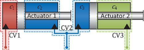
Figure 1 Example of a dual actuator hydraulic system with a fluid short circuit connection between chambers and .
Fluid short circuit connections were first investigated in [4, 8] for a hydraulic drive network where a dual actuator system is considered and different short circuit schemes are compared with the aim of designing an optimal drive system for a crane application. Indeed, an architecture incorporating a short circuit connection is found as the best match for the application when considering energy efficiency, reduction of maximum shaft torques, and reduction of hydraulic machine displacement sizes as design objectives. The same crane is subject for investigation in [9] which investigates and compares the drive sizes of many drive system architectures under certain load conditions. The paper highlights how the choice and sizing of a hydraulic drive network for an application is sensitive to the load requirements imposed on the design, especially regarding the simultaneity of actuator loads and movements. However, which exact hydraulic drive networks are included in the analysis is not presented, nor how these drive networks have been identified.
Another multi-pump system concept is presented in [10] in which a matrix of valves would make it possible to create short circuit connections between chambers. However, no specific multi-actuator systems architectures are investigated nor are any general valve-switching strategies presented for how to connect actuators and pumps. Reference [11] similarly considers two actuators and a valve matrix in combination with a digital displacement pump, where the individual pistons are divided into groups as were they separate pumps. In this case, short circuit connections are possible, though the paper specifically mentions that such operating conditions are carefully avoided. Other studies such as [12, 13] consider a valve matrix, but still apply control valves. In these cases a short circuit connection on the actuator side is not possible. A valve matrix in direct connection with the actuators could in general allow for short circuit connections regardless of which displacement machine is supplying the flow.
In [14, 15], a dual cylinder hydraulic drive network incorporating a fluid short circuit connection between the rod-side chambers is experimentally tested, hereby validating the satisfactory control of a hydraulic drive network incorporating a short circuit connection. The same system is investigated in [6], where the flow sharing capabilities of a short circuit connection are experimentally analyzed and verified, highlighting the importance of limiting resistive losses in the short circuit connection.
A triple cylinder hydraulic system with short circuit connections between three chambers (the rod side of one cylinder and the piston sides of the other two cylinders) is investigated in [7, 16] for the application in an excavator. The investigated hydraulic drive network is shown to have less installed motor power and with similar energy efficiency and installed hydraulic machine sizes compared to a standalone electro-hydraulic solution, while using less energy compared to a separate metering valve controlled solution. However, it is not discussed why or how the specific hydraulic drive network architecture was chosen nor how it was identified. In [17], a so designated “perfect solution” is briefly presented, incorporating short circuit connections between the rod side chambers of a triple cylinder system. Also here, no explanation is given on why the proposed architecture is considered the perfect solution, nor are any further modeling or characterization of this system given.
From the above mentioned works, it is clear that short circuit connections are important to consider when designing energy efficient hydraulic systems with few and small components – especially when considering electro-hydraulic direct drive systems in the form of hydraulic drive networks and similar. However, from the existing literature it is not clear how such meaningful short circuit connections can be made on a generic level and how to characterize systems incorporating fluid short circuit connections.
Fluid short circuit connections are not to be mixed up or compared with regenerative functions where, for example, the potential energy in a boom is to be regenerated [18] or when fluid is regenerated through a valve assembly from one side of an actuator to the adjacent side to enable faster movements, something that is investigated in [19, 20, 21, 22] and used in industry [23, 24]. In these works, such connections are at least partially controlled and only active under certain load situations. The theory and methods presented in this paper are, therefore, not valid for such regeneration type connections.
This paper aims to clarify the characteristics of fluid short circuit connections in hydraulic actuated systems and to showcase an exhaustive method for identifying every physically meaningful short circuit connection scheme for any number of dual-acting hydraulic actuators. Section 2 presents and analyzes some of the characteristics associated with a fluid short circuit connection and presents several examples. Section 3 introduces a few concepts of graph theory, intended for the reader that is unfamiliar with such concepts. Some of these graph theoretical concepts are essential for identifying all feasible short circuiting schemes. Section 4 presents an exhaustive method for identifying every short circuiting scheme and how these may be encoded for referencing and implementation into a computer program using graph theoretical methods. The presented approach is generic for any number of hydraulic actuators, both linear and rotary, though it is assumed that there are always two working chambers associated with each actuator.
2 Characterization and Modeling of a Hydraulic Short Circuit Connection
A hydraulic fluid short circuit connection is defined as a fixed physical connection between any two hydraulic chambers. Ideally, the connection is implemented in a way which completely equalizes the pressures between connected chambers and thus allows for a resistive free fluid flow between these chambers. The following assumes that each hydraulic actuator that is part of the system under investigation, must be individually controllable so a load force/torque and motion may be freely controlled.
An example of a dual actuator hydraulic system is shown in Figure 1 with a short circuit connection between chambers and resulting in the combined control volume CV2. Hence, there are a total of three control volumes in this system to which fluid must be individually supplied by some controlled hydraulic drive structure.
One of the main consequences and advantages of applying short circuit connections is that the number of control volumes which must be supplied by a drive system is decreased, hence resulting in fewer components in the drive system. The introduction of these hydraulic couplings needs to be accounted for in the control of the system which may limit the use of well known control approaches. However, recent studies [15, 6] have experimentally demonstrated the successful control of a hydraulic system incorporating a fluid short circuit connection and validated the potential benefits of a short circuit connection. The consequences of a short circuit connection on pressure and flow, as well as the interaction with actuators, are presented in the following and examples are given subsequently.
2.1 Pressure Coupling
The hydraulic force of a double acting hydraulic cylinder is found by summing the hydraulic forces on each side of the piston as Equation 1, where , are the chamber pressures and , are the piston areas. The forces acting on the piston rods associated with atmospheric pressure are neglected. Similarly, the output torque of a rotary hydraulic actuator like a hydraulic motor is found as Equation 2, where is the displacement per rotation.
| (1) | ||
| (2) |
Due to linearity, these expressions may be written as a linear system of equations as Equation 3. For simplicity, it is assumed that the chambers of a multi-actuator system are labeled sequentially i.e., labels for the piston and rod side chambers associated with the first actuator, labels for the piston and rod side chambers associated with the second actuator, and so forth. Areas and displacements are likewise labeled sequentially. The labeling of pressures follows the labeling of control volumes, which are also sequentially labeled, but not necessarily correlating with the chamber labels.
| (3) |
The vector represents the generalized forces: forces in the case of linear actuators and torques in the case of rotary actuators. Vector represents the pressures in control volumes. Matrix describes the area/displacement relation between pressures and generalized forces (including sign), defined as Equation 4. Here, the operator implies element-wise multiplication.
| (4) |
The matrix contains the information of areas/displacements of each chamber, thus having a size of (number actuator chambers and number of actuators, respectively). Areas are used to represent both areas of linear hydraulic actuators as well as displacements of rotary hydraulic actuators, though the relevant parameters should be entered based on the system. The matrix is a transformation matrix describing short circuit connections in a hydraulic system with chambers and is determined using Algorithm 1. The input to the algorithm is an edge list which is a two column matrix with each row indicating the two connection points of a fluid short circuit connection. The notation is used to index into row and column of the matrix, with indices starting from 1.
Algorithm 1 Obtaining transformation matrix describing fluid short circuit connections.
Input: , ,
Require:
Ensure: is sorted in increasing order
SUM ROWS OF :
for
do
Sum row to row of
end
for
DELETE REDUNDANT ROWS OF :
for
do
Delete row of
end
for
Output:
As an example application of Algorithm 1, the system of Figure 1 is considered giving and the edge list . The transformation matrix is initialized as an or identity matrix, giving the matrix Equation 5.
| (5) |
There is one edge in the edge list, so rows of need to be summed once according to the labels in the edge list: sum row 3 of to row 2 of , giving the matrix Equation 6.
| (6) |
Finally, delete the rows in from the second column of the edge list i.e., delete row 3 of , resulting in Equation 7.
| (7) |
The linear system Equation 3, representing a real hydraulic system, must have at least one solution in the algebraic sense, meaning that any combination of generalized forces must be obtainable through some combination of pressures. Furthermore, pressure is a physical unit that is bound to strictly positive values and, in practice, the pressure in any chamber should not get below the atmospheric pressure to avoid cavitation phenomena, potentially severely damaging components. A system on the form of Equation 3 should therefore have infinitely many solutions to be physically meaningful, implying that there are infinitely many combinations of pressures which result in some forces on the actuators. Hence, the system of equations has at least one free variable. This is equivalent to stating that the nullity (system size minus its rank) should be at least 1. It effectively means that the overall pressure level is variable for any output hydraulic force, assuring that no pressures become negative.
Pressures may be determined based on the external loads as the minimization problem Equation 8 with equality constraints from Equation 3 and inequality constraints defining minimum pressure values . Possibly, additional equality constraints may be added specifying a set-pressure for a specific control volume . The minimization function may simply be the sum of pressures or any norm of the pressure vector .
| (8) |
A side effect of a short circuit connection between chambers is that some combinations of actuator forces result in higher chamber pressures than if there were no short circuit connections. This may become a limiting factor if the required forces result in pressures exceeding the component pressure ratings for a given system. Therefore, it is vital to only make short circuit connections that do not limit the functionality of the mechanism.
From this analysis of the pressure couplings resulting from short circuit connections, some characteristics can be concluded:
1. Between hydraulic double acting actuators there can be at most short circuit connections and, if part of the actuators in a system are not coupled by short circuit connections, these may be seen as independent actuators.
2. Actuators may only be short circuited in a manner resulting in Equation 3 having infinitely many solutions, given some combination of generalized forces.
These characteristics are further exemplified through 6 examples presented in Section 2.4.
2.2 Flow Coupling
By short circuiting two hydraulic chambers, the inflow of the combined control volume is simply the sum of the flows to the short circuited chambers. The total volume flows resulting from short circuit connections are found as Equation 9, with positive flow defined as going into the volume. Here, are the flows into each individual actuator chamber (before any short circuit connections) and its height is defined by the number of chambers . is the transformation matrix representing the short circuit connections.
| (9) |
If there are no short circuit connections between any chambers, is simply an identity matrix, , and .
Applying fluid short circuits in a hydraulic system may result in fluid being shared between actuators, depending on the simultaneity between the motion of the actuators. This may in turn result in reduced flow demands compared to a drive system with no short circuit connections, hence components with reduced sizes may be applied potentially resulting in reduced system cost.
2.3 Actuator Dimensions
Though the choice of hydraulic actuators for a mechanism is not a focus of this paper, a few notes are given in this regard. A hydraulic actuator is a component that converts a hydraulic pressure potential to a force/torque or a mechanical movement, either linear or rotary. The choice of actuator size is a compromise between the gearing of force/torque and speed. For example, increasing the diameter of a hydraulic cylinder results in a higher output force for the same hydraulic pressure, but also increasing the flow requirements for the same piston speed. As discussed in Section 2.1, the introduction of fluid short circuits may give rise to higher pressures for the same output force, which may be a limiting factor if these pressures exceed the component pressure ratings of the system. Therefore, it may be sensible to include the actuator sizes as variables in the design and sizing process of a hydraulic system, since this may allow short circuiting schemes that would otherwise result in excessively high pressures but, nevertheless, may be a good design choice when considering other design criteria such a size of the hydraulic drive system. As outlined in Section 2.2, hydraulic systems incorporating fluid short circuits are characterized by direct flow sharing between actuators. Hence, depending on the simultaneity between actuators, the increased flow resulting from larger actuators might not be causing a higher flow demand from the hydraulic supply system. The opposite case of decreasing actuator sizes to increase pressure levels, but decrease fluid flows, may also be sensible. Again, this might decrease the load requirements to the drive system components and thus their size.
2.4 Examples of Feasible and Infeasible Short Circuit Connections
The following examples illustrate some of the conclusions drawn in the previous sections. In particular, they aim to show which types of short circuit connections are feasible or infeasible, that is, whether they severely limit the force-producing capacity of the actuators. Additionally, the examples demonstrate how the edge list is defined in different scenarios.
Example 1: 1 Cylinder with 1 SC
Consider Figure 2, where a single hydraulic cylinder has had both its chambers short circuited. The resulting hydraulic force on the piston and the control volume flows are given by Equation 10. It is clearly seen that the hydraulic force applied can only be positive, assuming , which is analogous to a plunger cylinder (single chamber cylinder) with the effective pressure area of the piston given by , and the cylinder relies on external forces to move back the piston. The nullity of the A-matrix is therefore 0. Hence, this is the simplest example of a short circuiting scheme that is considered physically infeasible. Consequently, a system with at least two actuators is needed for a fluid short circuit to be feasible.
| (10) |
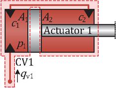
Figure 2 Example 1 system with 1 actuators (hydraulic cylinder) with a short circuit between chambers and .
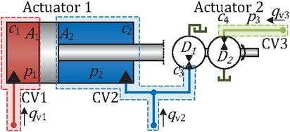
Figure 3 Example 2 system with 2 actuators (one hydraulic cylinder and one hydraulic transformer) with a short circuit between chambers and .
Example 2: 2 Actuators with 1 SC
Consider now the system illustrated in Figure 3, comprised by a cylinder and a hydraulic transformer actuator type, with the latter acting as a hydro-mechanical gear. Equation 11 shows the edge list, describing the short circuit connection, as well as the relation between pressures and actuator force and torque having a nullity of 1. Equation 12 describes the total flow into the three control volumes, of which control volume 2 (CV2) is composed of chambers and . For a rotary actuator, the associated chamber volumes are merely the fluid volumes associated with hoses and pipes. The hydraulic transformer is chosen to showcase the generality of the method. For a hydraulic transformer the in/out flows may be unequal implying . This is thus an extension to the simpler case of a hydraulic motor/pump in which case Equations 11 and 12 are still valid by setting . The short circuiting scheme analyzed her is considered physically feasible since any combinations of actuator force and torque are achievable (disregarding any upper pressure limitations).
| (11) | ||
| (12) |
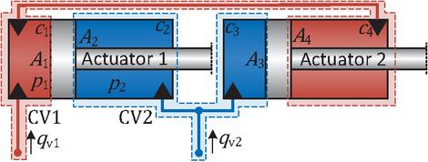
Figure 4 Example 3 system with 2 actuators (two hydraulic cylinders) with two short circuit connections between chambers and , and between chambers and .
Example 3: 2 Cylinders with 2 SCs
Considering now the dual cylinder system in Figure 4. This is structurally similar to the system of example 2, though this system has an additional short circuit connection between chambers 1 and 4. The describing equations are given by Equations 13 and 14. From Equation 14 it is seen that fluid is exchanged through the short circuit connections when the pistons are moving in the same direction. The two actuators are doubly coupled and there are no free variables in the transformation matrix between forces and pressures of Equation 13 as the nullity is 0. With this system, it is only possible to create forces on the two pistons of the same size and in opposite directions and hence, this is another example of a short circuiting scheme that is infeasible unless one intends to share the load between two cylinders.
| (13) | |
| (14) |
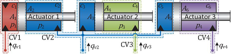
Figure 5 Example 4 system with 3 actuators (three hydraulic cylinders) with 3 short circuit connections between chambers , and .
Example 4: 3 Cylinders with 2 SCs
Example 4, illustrated in Figure 5, is a system with three hydraulic cylinders and two short circuit connections connecting chambers and all together resulting in four control volumes. The edge list and relation between forces and pressures are given by Equation 15. The nullity of the matrix is 1 and therefore the pressure level in the system is freely adjustable, given any combination of piston forces and hence the system is considered feasible. Equation 16 describes the flow relations of the system. It is seen that flow is exchanged through the short circuit connections from chamber to chambers and if all pistons move out (conversely for inward piston movements). Flow may be exchanged between chambers and if piston 2 and 3 move in opposite directions.
| (15) | |
| (16) |
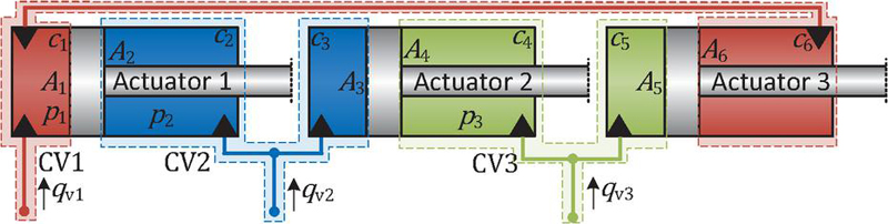
Figure 6 Example 5 system with 3 actuators (three hydraulic cylinders) with 3 short circuit connections between chambers and , between and , and between and .
Example 5: 3 Cylinders with 3 SCs
The system of Example 5, illustrated in Figure 6, has three hydraulic cylinders and three short circuit connections coupling all three actuators in a pairwise manner, as given by the edge list in in Equation 17 and resulting in the flow couplings given in Equation 18. The nullity of the A-matrix relating forces and pressures is 0 for this system. This means that there is only a single combination of pressures that can result in a given combination of piston forces. This system is thus another example of a physically infeasible short circuiting scheme.
| (17) | |
| (18) |
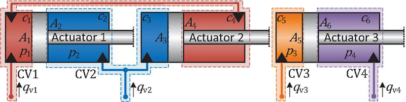
Figure 7 Example 6 system with 3 actuators (three hydraulic cylinders) with 2 short circuit connections between chambers and , and between and .
Example 6: 3 Cylinders with 2 SCs, Case Two
This system illustrated in Figure 7 represents a case where only part of the system is coupled. Hence, though the nullity of the -matrix in Equation 20 is 1 (one free variable), cylinders 1 and 2 are coupled in a way that leaves only a single solution for pressures and given some forces. This is seen in the fact that pressures and affect only the force of cylinder 3–columns three and four in the -matrix have nonzero values only in the third row. Therefore, the three cylinders should be seen as two separate systems, where cylinder 1 and 2 make up the same system as example 3 with two cylinders and two SCs, and cylinder 3 is an independent system in the sense of describing actuators coupled by short circuit connections.
| (20) | |
| (21) |
3 Some Supporting Notes on Graph Theory
This section is intended as a supporting note on some of the key concepts within graph theory and combinatorics, relevant to the analysis of short circuit connections. The topic of combinatorics is associated with combinations, arrangements, permutations, partitions and similar, whereas graph theory is the study of graphs (or networks) and the connectivity within these. For more comprehensive insights beyond the following, consider e.g. [25, 26, 27].
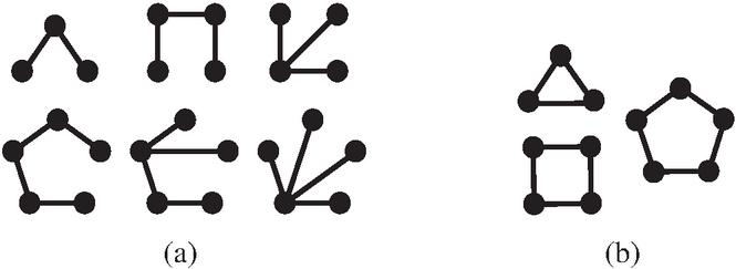
Figure 8 Example of (unlabeled) graphs on 3, 4, and 5 nodes. (a) Tree graphs. (b) Cycle graphs.
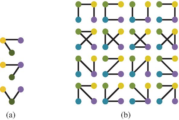
Figure 9 All labeled (a) 3-trees and (b) 4-trees. Colors represent node labels.
A graph is composed of vertices (or nodes) and edges (or connections). A node is represented visually by a dot whereas an edge is represented by a line between two nodes. A graph is thus constituted by a set of nodes and edges. Examples of graphs are shown in Figure 8. The nodes in a graph may be labeled so that each node is distinguishable from the others, for example by numbering the nodes sequentially. In Figure 9 the nodes have been labeled with colors, which may as well be interpreted as the numbers 1–4.
An edge may be directed, though only undirected edges are considered in this work which represent a connection in both directions between two nodes. The edges in a graph can be represented by an edge list which, together with the number of nodes, gives complete information about the graph. An edge list is a matrix of size , with being the number of edges and thus, each row in the edge list represents an edge. The columns in the edge list represent the connecting nodes of each edge. For undirected edges the order of the connecting nodes is of no importance, though in this paper it is assumed that an edge list is sorted so that the first column of each row contains the lowest numbered node label and that rows are sorted in ascending order so that the first row describes the edge with the lowest node labels.
If the edges in a graph are so that it is possible to go from one node to another, and end up back at the first node, without repeating any edge, the graph is said to contain a cycle (see Figure 8b). If, on the other hand, a graph contains no cycles but a path may be found from any node to any other node the graph is said to be a tree (see Figures 8a and 9 for examples). A graph is a tree if two of the following statements hold – the remaining statement is then implied:
1. The graph with nodes has edges.
2. The graph is acyclic.
3. The graph is connected.
If there are no cycles in a graph but it is composed of several components it is said to be a forest–each component in a forest is thus itself a tree. There exists a convenient encoding of trees called a Prüfer sequence. For a tree with n nodes its Prüfer sequence is the set with .
4 Identification of Fluid Short Circuit Connection Schemes
The set of all feasible short circuit connections for any number of hydraulic actuators is found by comparing the physical understanding of hydraulic short circuit connections to concepts of graph theory. It is noted that short circuit connections should first and foremost be seen as a hydraulic coupling between actuators, while the details of which exact chambers are connected are of less importance. Furthermore, it is noted that the physical characteristics presented in Section 2.1 are directly equivalent to the graph theoretical description of a tree-graph presented in Section 3.
This section presents a method to identify all (but only) physically feasible short circuit connections schemes for any hydraulic system. The method may be divided into three main steps as summarized in Algorithm 2, which are to be executed when considering a hydraulic system with actuators.
Algorithm 2 Identification and listing of physically meaningful short circuit schemes for actuators.
1: Create possible set partitions of the set {1,}.
2: For each sub-set in each set partition, make possible labeled trees, creating labeled forests. Section 4.1
3: For each edge in every forest, make possible chamber assignments and delete duplicates. Section 4.2
Step 1 of the algorithm is to find set partitions of the set of actuators . This is a well known procedure described e.g. in [26] and several software implementations may be found online. Table 1 presents the set partitions for -, -, and -sets. A partition of a set of actuators may be interpreted as dividing the actuators of a system into groups which are in some way connected by fluid short circuit connections, without accounting for which exact chambers are to be connected. Each group of actuators may then be refereed to as a component in the terminology of graph theory.
Table 1 List of set partitions for sets of size 2–4
| 2 elements | 3 elements | 4 elements |
| (lr)1-1 (lr)2-2 (lr)3-3 {{1}, {2}} | {{1}, {2}, {3}} | {{1}, {2}, {3}, {4}} |
| {{1,2}} | {{1,2}, {3}} | {{1,2}, {3}, {4}} |
| {{1,3}, {2}} | {{1,3}, {2}, {4}} | |
| {{1}, {2,3}} | {{1,4}, {2}, {3}} | |
| {{1,2,3}} | {{1}, {2,3}, {4}} | |
| {{1}, {2,4}, {3}} | ||
| {{1}, {2}, {3,4}} | ||
| {{1,2}, {3,4}} | ||
| {{1,3}, {2,4}} | ||
| {{1,4}, {2,3}} | ||
| {{1,2,3}, {4}} | ||
| {{1,2,4}, {3}} | ||
| {{1,3,4}, {2}} | ||
| {{1}, {2,3,4}} | ||
| {{1,2,3,4}} |
Step 2 of the algorithm, identifying label forests for each set-partition, is described in Section 4.1 and step 3, assigning chambers and removing duplicate short circuiting schemes, is described in Section 4.2. The output of the algorithm is a number of unique edge lists which represent each short circuiting scheme that is physically feasible for the set of actuators.
4.1 Identification of Labeled Forests
Having divided the set of actuators into components using set partitions, the next step is to consider each set partition one at a time. For a given set partition, it is given that each component is somehow connected within itself, but is not connected to other components. From Section 2.1, it is defined that there can be at most one less short circuit connections than there are actuators; . Following intuition of graph theory, it is realized that each component is a tree-graph and subsequently, the collection of components are forest-graphs.
Identifying all labeled (actuator) forests is a matter of recursively making each possible tree of every component. This may be done easily using the Prüfer encoding scheme of graph trees from which edge lists may be found, describing the connections between actuators.
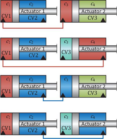
Figure 10 Illustration of the four possible chamber assignments for the short circuit connection between two actuators.
4.2 Assignment of Actuator Chambers
The last part of the method is to take each labeled (actuator) forest and make all possible assignments of chambers where, for each actuator there are two possible chambers to which a connection could be made, and hence there are possible chamber assignments for each short circuit connection as illustrated in Figure 10. To be able to perform the assignment of chambers in a generic and programmatic way, Equation 22 is defined. This describes the mapping from connections between actuators defined in step 2 of Algorithm 2, to the more specific fluid short circuit connections between actuator chambers, .
| (22) |
All three matrices and have the same size: . Matrix has only binary entries and is used to assign the chambers. Each row in is related to one edge, similar to the edge list. A zero indicates the connection to the first chamber of an actuator while a one indicates the connection to the second chamber of an actuator. For example, the matrices associated with the short circuit connections of Figure 10 are, from top to bottom respectively, , , , , while the actuator edge list is in all cases. Applying Equation 22 for these examples results in Equation 23 which are the four edge lists describing possible short circuiting schemes for two actuators. All possible chamber assignments are thus made by constructing each possible matrix of zeros and ones and applying Equation 22.
| (23) |
While all edge lists in Equation 23 are distinct, this is not always the case when dealing with systems with three or more actuators. In some cases, applying Equation 22 with different actuator edge lists may result in a similar chamber edge lists for certain assignment of chambers.
An example of such a case is visualized in Figure 11 showing six different graphs with Figures 11a, 11c and 11e (left column) representing connections between actuators and Figures 11b, 11d and 11f (right column) representing connections between specific actuator chambers. Note that the latter three graphs all connect chambers and in some way which, from a physical perspective, are all equivalent to combining the three chambers into a single control volume as in Figure 5 of Section 2.4, example 4.
Applying the associated edge lists of Figure 11 to Equation 22 results in Equations 24 to 26. The chamber edge list of Equation 25 is in the simple form where the labels have the lowest value while preserving the needed information–from the physical interpretation this is congruent to the chamber edge lists of Equation 24 and (26).
| Figures 11 a+b: | (24) | |||
| Figures 11 c+d: | (25) | |||
| Figures 11 e+f: | (26) |
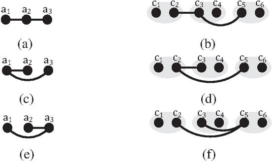
Figure 11 Example of three different actuator trees ((a), (c), and (e)) which, after assignment of chambers result in the same connection of chambers and ((b), (d), and (f)).
4.3 Example: Short Circuiting Schemes for 2 Actuators
In this example, the presented methods are applied to finding feasible short circuiting schemes for two actuators with the labels {1} and {2}.
Firstly, the possible set partitions which are {{1},{2}} and {{1,2}} are found, as outlined in Table 1. In the first set partition, there are two subsets with one element in each. This represents the solution with no short circuit connections between chambers.
We are then left with the second set partition consisting of a single subset with both actuator labels in it. The next step is to identify all labelled trees of each subset. There is only one subset with at least two elements, and this subset contains two elements which can only be connected into a tree-graph in a single manner, say by connecting the two elements. Hence, actuator 1 and 2 are connected in this case. Next, we assign chambers in all possible configurations. There is one connection with two possible chambers in each end of the connection, giving a total of 4 possible chamber connections (same as Figure 10). If we label the individual chambers in sequential order as [1,2,3,4], the four possible short circuiting schemes are , , , (same as Equation 23). In this case, there are no duplicates that need to be deleted. Including the null-solution of not making any short circuiting connections, there are thus a total of 5 unique short circuiting schemes for two actuators.
4.4 Example: Short Circuiting Schemes for 3 Actuators
For three actuators with the labels {1}, {2} and {3}, there are five set partitions as seen in Table 1. The first set partition {{1},{2},{3}} is the null-solution with no short circuit connections. The next three set partitions all contain two subsets with one and two elements respectively. This represents that there is a single short circuit connection, similar to the previous example with two actuators. Hence, the possible short circuiting schemes for 3 actuators and a single short circuit connections are given in Table 2.
Table 2 Chamber short circuit connection schemes for 2 actuators and 1 SC.
| Act. 1&2 connected | Act. 1&3 connected | Act. 2&3 connected |
| (lr)1-1 (lr)2-2 (lr)3-3 | ||
The last set partition represents the short circuit connections schemes where all three actuators are connected through two fluid connections. This is equivalent to a (labeled) tree graph with three nodes which can be made in three distinct ways (by having each of the nodes as the center node) as visualized in Figure 9a. When assigning specific actuator chambers there are two possible structures of short circuit connections: either the two fluid connections have a common chamber effectively coupling three chambers together or, the two fluid connections result in two separate short circuit connections. This can be done in 8 and 24 ways respectively as outlined in Table 3. Including the null-solution of having no short circuit connections, there are thus a total of 45 unique ways that the chambers of three actuators can be connected.
Table 3 Chamber short circuit connection schemes for 3 actuators and 2 SCs
| Triple connection | Two separate connections | |
| (lr)1-1 (lr)2-3 | , | , |
| , | , | |
| , | , | |
| , | , | |
| , | , | |
| , | , | |
| , | , | |
| , | , | |
| , | , | |
| , | , | |
| , | , | |
| , | , |
Table 4 Number of feasible fluid short circuit schemes for 2–6 hydraulic (dual chamber) actuators
| Number of actuators | |||||
| SCs | 2 | 3 | 4 | 5 | 6 |
| (lr)1-1(lr)2-2 (lr)3-3 (lr)4-4 (lr)5-5 (lr)6-6 0 | 1 | 1 | 1 | 1 | 1 |
| 1 | 4 | 12 | 24 | 40 | 60 |
| 2 | 32 | 176 | 512 | 1,120 | |
| 3 | 240 | 1,968 | 8,784 | ||
| 4 | 1,600 | 27,344 | |||
| 5 | 10,000 | ||||
| Total | 5 | 45 | 441 | 4,121 | 47,309 |
5 Discussion
Section 4.3 and Section 4.4 applied the proposed algorithm for identifying feasible short circuit connections for 2 and 3 actuators respectively. Applying the algorithm for up to 6 actuators and counting the number of unique short circuiting schemes results in Table 4. It is seen that the number of short circuiting schemes increases in an exponential manner with the number of actuators, showing the importance of being able to evaluate such systems in a generic programmatic manner using the modeling approach presented in Section 2 as it would be impractical to evaluate hundreds or thousands of systems manually. Especially considering that these are only the short circuiting schemes without any regard for which drive system is applied. If several drive system architectures are to be evaluated for each short circuiting scheme, it quickly becomes infeasible to manually evaluate all combinations, even for 2 or 3 actuators.
Considering the many system architectures possible, a programmatic evaluation method is required regardless if the evaluation is performed off-line, i.e. when designing a new system to be built, or if the evaluation is performed on-line, i.e. the system architecture is switched during operation which is possible with a valve-matrix or similar. The evaluation of system architectures can be approached in several ways:
1. Exhaustive (or enumerative) evaluation methods which guarantee that the global optimum is found. Such methods include brute-force, branch-and-bound and dynamic programming. These methods are most appropriate when computation time is not critical, such as when designing a future series produced system. Contrarily, the long computation time may be a hindrance if the evaluation needs to take place on-line on a running machine to continuously adapt and optimize the architecture to the present working conditions.
2. Stochastic (or heuristic) evaluation methods which are not guaranteed to find the global optimum. Such methods include Monte Carlo methods and “nature-inspired” optimization algorithms such as genetic algorithms. These methods may be applied if the design space of possible architectures is too large for exhaustive methods to be applied. In general, they may be applicable if computation time is critical and it is acceptable that the identification of the optimum architecture is not guaranteed–i.e. if it is sufficient to find a “somewhat good” architecture.
3. Data driven black- or gray-box approaches such as machine learning. These methods could be viable and apt for on-line continuous adaptation of the system architecture, especially if combined with forecasting methods, so that the architecture is adapted based on the foreseeable working conditions instead of only current working conditions. However, vast amount of data are required, which does not yet exist. Data driven approaches are thus considered inaccessible until further studies are presented applying exhaustive or stochastic optimization approaches.
An important question is whether short circuiting schemes can be evaluated in isolation, i.e., without considering any specific drive system, to distinguish between “good” and “bad” connection schemes. Several considerations may be relevant in this context.
Firstly, as pointed out in Section 2, the short circuiting of actuator chambers entails that the chamber pressures need to be higher than if there were no connections for some combination of actuator forces. Therefore, it would be straightforward to evaluate each short circuiting scheme through some load cycle using Equation 8 to calculate the chamber pressures to obtain the required actuator forces. If a pressure becomes too high, the given short circuit scheme could be disregarded though, as pointed out in Section 2.3, one could then choose larger actuators requiring less pressure for achieving the same force.
Secondly, Equation 9 may be used to find the fluid flows to the control volumes through some load cycle. One could then prioritize short circuit schemes which minimize the flow, which is to be handled by some drive system. However, it is not guaranteed that small flows are directly correlated with other design objectives such as total system cost or energy efficiency.
Finally, given the pressure and flow data, it is possible to analyze the power flows through short circuit connections and control volumes. However, caution is warranted, as the power flows associated with the actuators do not necessarily correlate directly with the previously discussed design objectives of system cost and efficiency. Moreover, it is important to note that such analyses cannot be conducted at a generic level; rather, they are highly dependent on the specific load cycle under consideration. Therefore, special care must be taken when selecting and defining the load cycle.
6 Conclusion
Making fluid short circuit connections in a hydraulic system has been proposed in recent literature as a means to decrease the amount of components needed to drive the system as well as enabling fluid sharing directly between actuators, potentially decreasing the load demands on the drive system resulting in smaller components and a more efficient system. Such short circuit connections are in this paper described and characterized with a focus on which short circuiting schemes are physically feasible. When designing a hydraulic system, it is important to know the complete design space to be able to find the optimal design solution. Realizing that methods from graph theory can be applied, a method is described on how to make an exhaustive list of all feasible short circuiting schemes. Each scheme is described as an edge list indicating the relevant short circuit connections. The method initially creates some short circuiting schemes which in a hydraulic sense are equivalent, so duplicate solutions are deleted. The result is an exhaustive list with unique solutions, each describing a fluid short circuiting scheme. This information can then be used in a design process of a hydraulic system when searching for an optimal system architecture.
References
[1] Z. Quan, L. Quan, and J. Zhang. Review of energy efficient direct pump controlled cylinder electro-hydraulic technology. Renewable and Sustainable Energy Reviews, vol. 35, pp. 336–346, 2014. https://www.sciencedirect.com/science/article/pii/S1364032114002639.
[2] G. Altare, A. Vacca. A Design Solution for Efficient and Compact Electro-hydraulic Actuators. Procedia Engineering, vol. 106, pp. 8–16, 2015. https://doi.org/10.1016/j.proeng.2015.06.003.
[3] E. Busquets. Advanced control algorithms for compact and highly efficient displacement-controlled multi-actuator and hydraulic hybrid systems. Purdue University, 2016. https://www.proquest.com/dissertations-theses/advanced-control-algorithms-compact-highly/docview/1848166438/se-2.
[4] L. Schmidt and K.V. Hansen. Electro-Hydraulic Variable-Speed Drive Networks—Idea, Perspectives, and Energy Saving Potentials. Energies, vol. 15:1228, 2022. https://doi.org/10.3390/en15031228.
[5] D. Fassbender, C. Brach, and T. Minav. Energy-Efficiency Comparison of Different Implement Powertrain Concepts to Each Other and Between Different Heavy-Duty Mobile Machines. International Journal of Fluid Power, vol. 25(02), 127–144. https://doi.org/10.13052/ijfp1439-9776.2521.
[6] M. van Binsbergen-Galán, B. Videbæk, K.V., Hansen, and L. Schmidt. Experimental Investigation of Hydraulic Power Sharing Potential in a Dual Cylinder Electro-Hydraulic Variable-Speed Drive Network. Proceedings of the BATH/ASME 2024 Symposium on Fluid Power and Motion Control. Bath, United Kingdom. September 11–13, 2024. V001T01A021. ASME. https://doi.org/10.1115/FPMC2024-140322.
[7] L. Schmidt, M. v. Binsbergen-Galan, R. Knöll, M. Riedmann, B. Schneider, and E. Heemskerk. Energy efficient excavator implement by electro-hydraulic/mechanical drive network. International Journal of Fluid Power, vol. 25, no. 04, p. 413–438, 2024. https://doi.org/10.13052/ijfp1439-9776.2541.
[8] L. Schmidt and S. Ketelsen and K.V. Hansen. Perspectives on Component Downsizing in Electro-Hydraulic Variable-Speed Drive Networks. Proceedings of the BATH/ASME Symposium on Fluid Power and Motion Control, 2022. https://doi.org/10.1115/FPMC2022-89547.
[9] M. van Binsbergen-Galán and L. Schmidt. Determination of Load Collective for Sizing of a Hydraulic Drive Network System Considering Simultaneity Between Actuator Loads. Proceedings of the ASME/BATH Symposium on Fluid Power and Motion Control, 2023. https://doi.org/10.1115/FPMC2023-109823.
[10] Tozzi C. Gama, A, Heybroek, K, and Ericson, L. An Analysis of a Multi-Pump System for Actuator Operation in Electric Mobile Machinery. Proceedings of the ASME/BATH 2023 Symposium on Fluid Power and Motion Control. Sarasota, Florida, USA. October 16–18, 2023. V001T01A023. ASME. https://doi.org/10.1115/FPMC2023-111452.
[11] Heitzig, Stefan and Sgro, Sebastian and Theissen, Heinrich. Energy efficiency of hydraulic systems with shared digital pumps. International Journal of Fluid Power (Taylor & Francis), vol. 13, no. 03, p. 49–57, 2012.
[12] J. Yao, P. Wang, Y. Yin, M. Li, and Y. Li. Power management of multi-source network hydraulic system with multiple actuators. Energy Conversion and Management, vol. 223, Nov. 2020, doi: 10.1016/j.enconman.2020.113247.
[13] R. Bao, T. Wang, and Q. Wang. A Multi-Pump Multi-Actuator Hydraulic System with On-Off Valve Matrix for Energy Saving. Proceedings of the 2019 IEEE/ASME International Conference on Advanced Intelligent Mechatronics (IEEE Access), Jun. 2019, pp. 1–6. doi: 10.1109/AIM.2019.8868810.
[14] L. Schmidt, K.V., Hansen, B. Videbæk, and M. van Binsbergen-Galán. Experimental Validation of a State Decoupling Method Applied to a Dual Cylinder Electro-Hydraulic Variable-Speed Drive Network. Proceedings of the BATH/ASME 2024 Symposium on Fluid Power and Motion Control. Bath, United Kingdom. September 11–13, 2024. V001T01A016. ASME. https://doi.org/10.1115/FPMC2024-140149.
[15] L. Schmidt and M. van Binsbergen-Galán. Electro-Hydraulic Variable-Speed Drive Network Technology - First Experimental Validation. Energies, 17(13):3192, 2024. https://doi.org/10.3390/en17133192.
[16] L. Schmidt and M. van Binsbergen-Galán and R. Knöll and M. Riedmann and B. Schneider and E. Heemskerk. Energy Efficient Excavator Functions Based on Electro-hydraulic Variable-speed Drive Network. Proceedings of the 14th International Fluid Power Conference (14. IFK 2024), 2024. https://doi.org/10.13052/rp-9788770042222C66.
[17] M. Vukovic, R. Leifeld and H. Murrenhoff. STEAM – a hydraulic hybrid architecture for excavators. Proceedings of the 10th International Fluid Power Conference — Dresden 2016, 2016. https://core.ac.uk/download/pdf/236373201.pdf.
[18] X. He, G. Xiao, B. Hu, L. Tan, H. Tang, S. He and Z. He. The applications of energy regeneration and conversion technologies based on hydraulic transmission systems: A review. Energy Conversion and Management, vol. 205, 112413, 2020. https://doi.org/10.1016/j.enconman.2019.112413.
[19] P. Marani, G. Ansaloni and R. Paoluzzi. Load sensing with active regeneration system. Proceedings of the JFPS International Symposium on Fluid Power, 2008, Volume 2008, Issue 7-3, Pages 617-622. https://doi.org/10.5739/isfp.2008.617.
[20] J. Andruch and J. Lumkes. Regenerative Hydraulic Topographies using High Speed Valves. SAE Technical Paper 2009-01-2847, 2009, https://doi.org/10.4271/2009-01-2847.
[21] J. Li, J. Zhao and X. Zhang. A Novel Energy Recovery System Integrating Flywheel and Flow Regeneration for a Hydraulic Excavator Boom System. Energies, 2020, 13(2), 315. https://doi.org/10.3390/en13020315.
[22] D. Padovani. Leveraging Flow Regeneration in Individual Energy-Efficient Hydraulic Drives. Proceedings of the ASME/BATH 2021 Symposium on Fluid Power and Motion Control. Virtual, Online. October 19–21, 2021. V001T01A013. ASME. https://doi.org/10.1115/FPMC2021-68594.
[23] Technical tips, regenerative valves. SUN Hydraulics, 1995. https://www.sunhydraulics.com/sites/default/files/media_library/tech_resources/int_assm_regen.pdf. Accessed 2025-02-14.
[24] Counterbalance Valves With Regenerative Function. Bosch Rexroth. https://apps.boschrexroth.com/products/compact-hydraulics/CH-Catalog/pdf/Counterbalance_with_regenerative.pdf. Accessed 2025-02-14.
[25] N. Biggs, E. Lloyd, and R. Wilson. Graph Theory, 1736-1936. Clarendon Press, 1976
[26] P. Mladenovic. Combinatorics: A Problem-Based Approach. Springer, Cham, 2019. https://doi.org/10.1007/978-3-030-00831-4.
[27] F. Harary and E. Palmer. Graphical Enumeration. Elsevier, 1973. https://doi.org/10.1016/C2013-0-10826-4.
Biographies

Mikkel van Binsbergen-Galán received his M.Sc. degree in engineering (mechatronics) from Aalborg University in 2022. He is currently a Ph.D. Fellow at AAU Energy, Aalborg University, working with the design of drive systems for mechatronic systems with a special focus on hydraulic systems and the components associated with such systems.

Lasse Schmidt received the M.Sc. degree in engineering (mechatronics) from Aalborg University, Denmark, in 2008. From 2008 he was with the application engineering group of Bosch Rexroth A/S, Denmark, and from 2010 an industrial Ph.D. fellow also associated with Aalborg University. He received the Ph.D. degree in robust control of hydraulic cylinder drives in 2014. Subsequently, he has been a postdoctoral researcher at AAU Energy while concurrently being with Bosch Rexroth AG. Hereafter he became an Assistant Professor with AAU Energy. He is currently an Associate Professor with AAU Energy and heading research activities related to electro-hydraulic drive network technology, a field in which he is the founder of the fundamental design and control principles. He is the main author or co-author of nearly 70 scientific peer-reviewed publications, most of them on topics related hydraulic drives and systems control. Lasses current research interests are in design and control of electro-hydraulic drive networks and their integration into both mobile working machines and industrial systems.
International Journal of Fluid Power, Vol. 27_2, 297–326
doi: 10.13052/ijfp1439-9776.2722
© 2026 River Publishers