Towards a Conceptual Framework for Hydraulic Drive Networks and Their Key Elements
Mikkel van Binsbergen-Galán* and Lasse Schmidt
AAU Energy, Aalborg University, Aalborg, Denmark
E-mail: mbg@energy.aau.dk
*Corresponding Author
Received 21 May 2025; Accepted 13 February 2026
Abstract
Hydraulic drive networks enable efficient actuation of multi-actuator hydraulic transmission systems which incorporate different coupling mechanisms between the actuators. So far, the topics of hydraulic drive networks have mainly been centered around the use of variable-speed electric machines combined with fixed hydraulic displacement machines to enable actuation. However, actuation in hydraulic drive networks may be realized in multiple ways, including the use of variable hydraulic displacement machines in through-drive configurations with a single electric motor, hydraulically supplied hydraulic motor-pump configurations and so forth. This paper introduces a definition of hydraulic drive networks and presents a framework of its different coupling layers including fluid short circuit connections and flow couplings through hydraulic displacement machines. Requirements for the hydraulic displacement machines as well as different component configurations and their control degrees of freedom are discussed. Furthermore, the paper illustrates the possible design space of hydraulic drive networks that should be considered when searching for an optimal drive system architecture, considering for example component sizes and system efficiency as design objectives.
Keywords: Hydraulic drive network (HDN), flow couplings, pressure couplings, multi-actuator system.
Nomenclature
| Area | Vector of areas/displacements of actuators | ||
| Actuator chamber | Capacitances relating motion and pressure | ||
| Displacement | Capacitances relating flows and pressure | ||
| Force | Volume | ||
| Gearing ratio | Piston speed | ||
| Number of gear teeth | Actuator motion | ||
| Number of units | Fluid bulk modulus | ||
| Power | Rotational speed | ||
| Pressure | |||
| Fluid flow |
| EM | Electric machine |
| HM | Hydraulic displacement machine |
| ICE | Internal combustion engine |
| HDN | Hydraulic drive network |
| HHEA | Hybrid hydraulic-electric architecture |
| EDN | Electro-hydraulic variable speed drive network |
1 Introduction
Hydraulic systems with hydraulic displacement machines (HMs) directly connected to the actuators, without any inline control valves, have gained substantial research interest particularly due to high energy efficiency as conceptual losses, i.e. throttling losses, can be avoided. These systems may be denoted as primary controlled systems as the control mechanism(s) directly affects the hydraulic input(s) [1]. System types include compact/self-contained electro-hydraulic actuators (EHAs) [2, 3, 4], direct pump control [5, 6], direct drive [7], displacement control [8], common pressure rail with hydraulic transformers [9, 10, 11, 12], hybrid hydraulic-electric architecture (HHEA) [13, 14, 15, 16, 17], and electro-hydraulic variable-speed drive networks (EDNs) [18, 19, 20]. These drive systems are characterized by controlling the fluid flow supplied to the actuator chambers by varying the speed and/or displacement volume of the HMs, and by enabling electrification by applying electric machines (EMs) as prime movers. Basically, a hydraulic drive system functions as a gear between input and output mechanical power as illustrated in Figure 1. HMs are defined as any component, e.g. pump, motor or transformer type, that enables mechanical and hydraulic power conversion or convert hydraulic power between pressure levels without any conceptual losses. That is, assuming ideal components, there are no conversion losses, hence the input and output mechanical power of a hydraulic gear are equal. This is in contrast to valve based control, where power is modulated by throttling, meaning that power is intentionally dissipated for controlling the output power. Even though HMs and actuators are distinctly depicted in Figure 1, the components used for these purposes are often interchangeable, meaning that an HM could in theory be used as an actuator and vice versa, e.g. as in the case of a hydraulic motor.

Figure 1 Conceptual illustration of a hydraulic drive system functioning as a gear between mechanical inputs and outputs.
1.1 Hydraulic Coupling Mechanisms
EDNs employ electro-hydraulic drives, each comprised of an EM driving a fixed displacement HM with variable speed, and they are distinguished from other similar technologies by employing a centralized drive system to multiple actuators incorporating hydraulic couplings within the drive system which allows for hydraulic power sharing between actuator chambers. This is shown to allow for reduced energy conversion losses as well as reduced component sizes, depending on the drive network architecture and actuator load requirements [18, 19, 21, 20]. Such hydraulic coupling mechanisms may appear in two separate ways and examples hereof are visualized in Figure 2:
1. HMs connected between actuator chambers.
2. Fluid short circuit connections between chambers of different actuators.
A short circuit connection is defined as a fluid connection between two actuator chambers where fluid can flow without any (or little) friction, ideally entailing an equalized pressure in the entire combined control volume consisting of the connected chamber volumes as well as any hoses or pipes connecting these. Depending on the number of actuators and their chamber configurations, a multi-actuator system may incorporate several short circuit connections. For dual-chamber actuators, such as traditional double-acting cylinders and motors, a maximum of short circuit connections can be feasibly integrated without significantly compromising the actuators’ work capacity. A detailed analysis of how these short circuit connections can be realized is presented in [22]. Each short circuit connection introduced into a system reduces the number of control volumes that must be supplied by HMs by one. For systems with two dual-chamber actuators a single short circuit connection can be configured in four distinct ways. With three dual-chamber actuators, one short circuit connection allows for 12 possible configurations, while two connections yield up to 32 distinct arrangements.
HMs may be connected between two chambers of an actuator, comparable to some EHA concepts and similar, as well as between the chambers of separate actuators. These connections must be realized in a manner that allows independent flow control to each control volume. When designing an EDN consisting of independent volumes (either control volumes or reservoirs) a minimum of HMs are required to enable independent flow control. Such configurations are referred to as basic EDNs [23]. The paper investigates how these basic networks can be structured and finds that unique configurations are possible, with the number of volumes influenced by the presence of short circuit connections. Applying more HMs than the minimum required amount could be viable if redundancy or increased control functionality is needed.
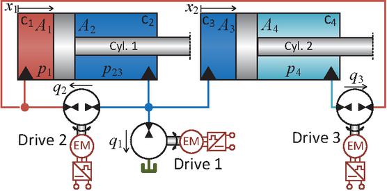
Figure 2 Example of an electro-hydraulic variable-speed drive network (EDN).
An example of an EDN with such hydraulic couplings is shown in Figure 2 for a dual-actuator system with two cylinders and three HMs. In this case any of the three inputs, i.e. rotational speed of the drive shafts, affect both cylinders. A fluid short circuit connection is present between chambers and thus creating a combined control volume. Drive 1, a hydraulic pump, connects this combined control volume to a hydraulic tank, drive 2 is connected between chambers and , and drive 3 is connected between chambers and . Equation 8 compares the standard formulation of flow continuity equations for a dual-cylinder system, illustrated in Figure 2, before and after introducing a fluid short circuit connection, with representing the aggregate flow contributions from the HMs. Before the short circuit connection is made, each actuator chamber 1–4 is described by its own continuity equation. After the short circuit connection between chambers and is introduced, these two chambers combine to a unified control volume with the common pressure . Here, are the bulk moduli and the total volume of each control volume.
| (1) |
Equation 8 highlights how hydraulic coupling mechanisms may affect the describing pressure dynamic equations of the system. Depending on the output work and the simultaneity between actuator loads and movements, the hydraulic couplings affect the drive system concerning e.g. needed number of components and their size as well as the energy efficiency. When designing a hydraulic drive system architecture for an application, it is desired to identify an optimal architecture when considering design objectives such as those just mentioned, supporting the need for assessing and comparing many different architectures.
EDNs rely on variable-speed electric machines as the active control elements. However, the control could also be realized by e.g. variable hydraulic displacement machines in through-drive configuration with a single electric motor, hydraulically supplied hydraulic motor-pump configurations or similar. Other such combinations are relevant to consider as they may allow for further component downsizing and efficiency improvement when pared with appropriate hydraulic couplings, since different components have different characteristics and power sharing abilities. Taking these approaches in consideration showcases the need for a more broad definition of drive networks. Hence, the term hydraulic drive networks (HDNs) is coined.
1.2 Outline and Contributions
The aim of this paper is to define hydraulic drive networks (HDNs) and characterize their structural elements, including the various coupling types and component configurations that can be combined to form a complete drive system. While EDNs have previously been studied in the context of dual- [18] and triple-actuator systems [19], this paper expands the design space by outlining a broader range of potential HDN architectures. These architectures may be relevant when designing new drive systems, particularly in the search for optimal configurations considering system size, efficiency, and cost.
It is beyond the scope of this paper to provide a comprehensive evaluation framework for all possible HDN configurations. Instead, the focus is on establishing a foundational definition and structural overview that can support future comparative studies and application-specific design efforts.
A definition of an HDN is presented in Section 2, including an overview of the component layers and coupling mechanisms that form the drive network architecture. Sections 3 and 4 discuss the key components and configurations that enable the proper functioning of an HDN, specifically:
• flow control using hydraulic machines (HMs), Section 3,
• mechanical coupling between HMs, Section 4.1, and
• the impact of prime mover characteristics on HDN design, Section 4.2.
2 Hydraulic Drive Networks: Definition and Conceptual Framework
An HDN is defined as a class of hydraulic drive systems that utilize HMs operating without conceptual losses—effectively functioning as a hydraulic gear. An HDN incorporates hydraulic coupling mechanisms such that at least one of the hydraulic flow inputs influences multiple mechanical outputs as illustrated in Figure 3. These outputs may include both motion and force or torque, in either linear or rotary actuators.
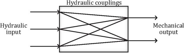
Figure 3 Conceptual diagram of drive system with hydraulic couplings.
2.1 Mathematical Definition of Hydraulic Coupling Mechanisms
Hydraulic coupling mechanisms are analyzed by considering Equation 9 which is a general representation of an HDN describing the load pressure dynamics on the actuators. Load pressures are virtual pressures which are proportional to the actuator force in the case of cylinders or proportional to the torque in the case of hydraulic motors. Load pressures are a weighted sum of the physical pressures associated with each actuator. For example, in the case of a dual-chamber cylinder, the load pressure is found as and . Hence, load pressures comprise a single state for each actuator and reflecting the mechanical output without needing to account for mechanical dynamics or possible mechanical couplings. The matrix maps the motion of actuators, i.e. piston velocity or shaft speed, into associated load pressure dynamics and is a function of the hydraulic capacitances and the areas or displacements associated with the actuators. The vector contains the motion of actuators, either linear or rotary. The matrix maps the input flows to load pressure dynamics and is also a function of the hydraulic capacitances and the areas or displacements associated with the actuators.
| (2) |
Coupling between an input and multiple outputs are present if has more than one non-zero entry in any column, meaning that a single flow input affects multiple load pressure dynamics. This may be a result both of the connections of HMs as well as any fluid short circuit connections between actuators. Short circuit connections between actuators furthermore entail that there are multiple non-zero entries in some row of , meaning that multiple actuator movements affect the dynamics of a single load pressure.
2.1.1 Example
Considering the system of Figure 2, the pressure dynamics are given as Equation 8 with a short circuit connecting chambers and . Flow directions are defined in the figure and all bulk moduli are assumed constant and equal . In this example, , and volumes are given as Equation 10.
| (3) | ||
The virtual load pressures are defined as a weighted differences between the pressures on each piston with the load pressure dynamics defined as Equation 11. Consequently, the and matrices are obtained as Equation 12 and Equation 13, respectively.
| (4) | ||
| (5) | ||
| (6) |
The matrix is seen to have only non-zero entries meaning that both piston movements affects both load pressures. Additionally, the matrix is also seen to have only non-zero entries implying that every flow input also affect both load pressure dynamics. Therefore, it can be concluded that the example system contains hydraulic coupling mechanisms and, since it has no conceptual losses, it can be classified as an HDN.
2.2 Structure of an HDN
An HDN comprises a set of interconnected layers, as visualized in Figure 4. These layers may include prime movers supplying mechanical energy, mechanical couplings between prime movers and multiple HMs, HMs forming flow couplings between control volumes, fluid short circuit connections between actuator chambers, actuators, and reservoirs. The core characteristics of an HDN are flow couplings and fluid short circuit connections, as outlined in the introduction, while HMs, mechanical couplings, and prime movers influence the operational behavior and control characteristics of the network as analyzed in Sections 3, 4.1 and 4.2, respectively.
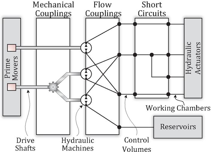
Figure 4 Visualization of the different layers that make up an HDN.
Hydraulic actuators may be of any type and may include any number of working chambers, such as plunger cylinders or multi-chamber configurations. In the context of HDNs, it may be advantageous to explore alternative actuator arrangements and sizes to better balance fluid flow capacity with pressure demands. A detailed analysis of such design considerations is left for future work.
A fluid reservoir is in practice necessary in any hydraulic system to allow for changes in total system volume due to actuator asymmetry as well as fluid compression and flow loss effects. A reservoir is able to provide and receive fluid to and from the control volumes and may be non-pressurized as in the case of a vented tank or pressurized as in the case of an accumulator. There could be several reservoirs connected in a system, possibly working at different pressure levels.
3 Configurations Realizing Flow Control
The HMs in an HDN may be of any type allowing proper functioning of the system, meaning that any movements and loads on the actuators are supported by the HMs and their flow coupling connections. The loads and movements of the actuators of a hydraulic system are defined by their target trajectory as well as external loads acting on the system. Actuator forces, hence control volume pressure levels, are dictated by the external loads and the HMs must be able to displace fluid between control volumes and reservoir independently of these loads and pressure levels. This means that, in general, all HMs must be able to operate in a 4-quadrant manner regarding flow and pressure difference. Furthermore, the flow of each HM must be independently controllable to be able to direct flow to any control volume as needed.
The flow of an HM is a product of the displacement (per rotation unit) and the rotational speed, of which at least one parameter needs to be variable for the output flow to be fully controllable. The dynamic performance of the speed or displacement ratio control is essential to match the dynamic requirements of the system—otherwise the controllability is compromised. Control of the displacement ratio is realized within the hydraulic machine while speed control is realized on the driving shaft such as by the prime mover.
Possible HMs achieving full flow control through speed and/or displacement ratio control are visualized in Figure 5. An arrow with a solid line indicates complete control of displacement ratio (orange arrow) or speed (blue arrow) with a dynamic performance that is appropriate for the application. An arrow with a dashed line indicates a somewhat limited control of displacement ratio or speed which may imply:
1. Dynamic control performance of displacement ratio or speed is insufficient for the applications e.g., an excavator with manually adjustable engine speed or a variable displacement pump with slow-varying displacement control mechanism.
2. Displacement or speed can be controlled only in a single direction.
3. Zero (or low) displacement ratio or speed is not possible.
Many commercially available machines exhibit such limitations, e.g. bent axis variable displacement machines which cannot operate with both positive and negative displacement in which case, at least some degree of speed control is also required to enable full flow control. In Figure 5, the HM in area (I) has full displacement ratio control while the shaft speed is considered fixed. Area (II) Shows an HM which is fully displacement ratio controlled but the speed is not completely controllable, e.g. it could be variable only in a single direction. Area (III) shows an HM with the maximum degree of flow control with full control of both displacement ratio and speed. Area (IV) shows an HM with some limitation in control of both displacement ratio and speed. This is only feasible if the combined control and related dynamics offer full flow control with proper dynamics. Area (V) shows an HM with full speed control and partial control of displacement ratio. Finally, area (VI) shows an HM with full speed control and fixed displacement per revolution.
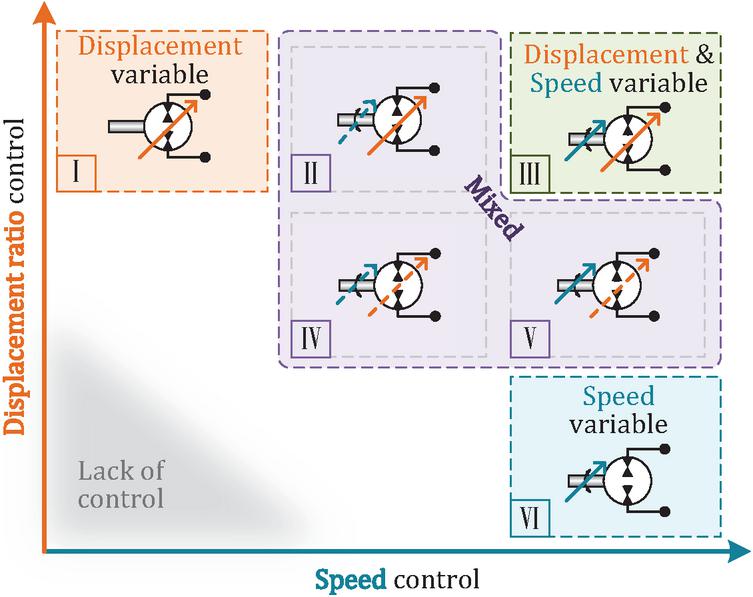
Figure 5 Possible configuration space of HMs achieving independent flow control through speed and/or displacement ratio control.
Control of displacement ratio is available with piston type HMs. Fixed displacement machines exist in various forms e.g., external gear, internal gear, vane, and piston machines. Speed control is realized on the shaft of the HM and is independent of the machine type, though some HM types may impose limitations, such as requiring uni-directional rotation.
3.1 Transformer Type HMs
For all HMs considered in the preceding discussion, the input and output flows of each displacement machine are theoretically equal i.e., (neglecting any leakage and compression effects). A special case of an HM is one that creates a gearing of the flow so that the input and output flows satisfy . Such hydraulic machines are considered as transformer type HMs. A main difference from other notions of hydraulic transformers is that a prime mover is connected to the shaft moderating power as needed and allowing (theoretically) for any gearing ratio.
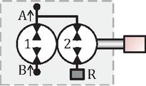
Figure 6 Transformer type HM.
A general representation of a transformer type hydraulic machine is presented on Figure 6. The transformer consists of a primary unit connecting the A- and B-ports and a secondary (boost) unit connecting the A-port with a hydraulic reservoir (R-port). The flows of the transformer are given as Equation 14, with the displacement ratio between flow A and B depending on the displacements of the primary and secondary units, which can be of any size and possibly with variable displacements. The considerations regarding flow control presented previously are equally valid when considering the primary unit of the hydraulic transformer, while the controllability of the secondary unit is related only to the flow gearing ratio.
| (7) |
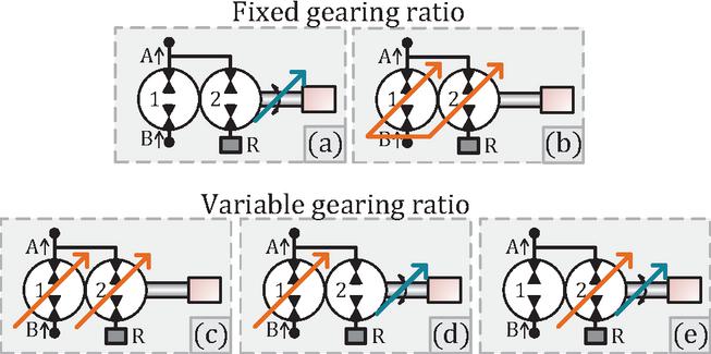
Figure 7 Transformer types achieving fixed or independent flow gearing ratios.
Examples of speed and displacement variability of a transformer are shown on Figure 7. A fixed gearing ratio, , is achieved if both units are fixed displacement (Figure 7a), or if both units are displacement variable and their displacement proportions are equal (Figure 7b) regardless of whether the speed is controllable. If the primary unit is displacement variable and the flow of the secondary unit is adjustable through either displacement (Figure 7c) or speed (Figure 7d), the input and output flows of the transformer are independent, . Such a transformer with independent flows may be controlled to have a certain, possibly varying, flow gearing while the additional degrees of freedom are used for secondary control objectives such as optimizing the operation for maximum energy efficiency.
On the other hand, if a transformer with independent flows is controlled without any regard to flow gearing, the transformer might as well be considered as two independent HMs mounted in tandem on the same shaft. This is discussed further in Section 4.1. Finally, if the primary unit is fixed displacement (speed control is thus required) and the secondary unit is displacement variable (Figure 7e), the flow gearing ratio is variable, but the flows are not independent since zero input flow implies zero output flow. Of course, a transformer with the possibility of varying the flow gearing ratio could be controlled to have a fixed flow gain, if this is desired.
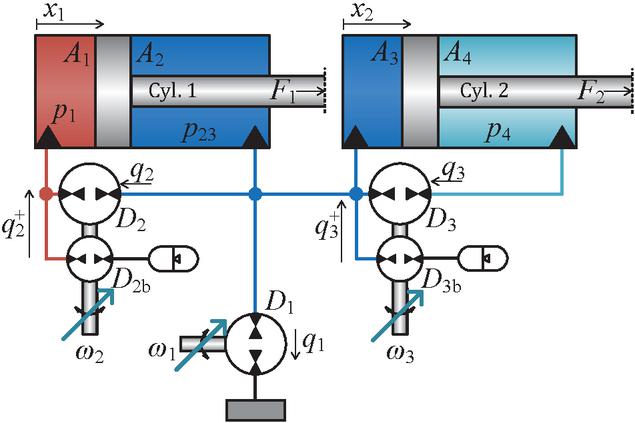
Figure 8 Example of a hydraulic drive network with two transformer type HMs, creating a gearing of the flow between control volumes.
3.1.1 Example HDN with Transformer Type HMs
An example of an HDN for a dual-actuator system is shown in Figure 8. The system actuators are differential cylinders incorporating a fluid short circuit connection between chambers 2 and 3 (rod side of cylinder 1 and piston side of cylinder 2) similar to the system in Figure 2. A transformer type HM is placed on each cylinder between the piston and bore side, while a standard HM connects the short circuited chambers to a hydraulic reservoir. For illustration purposes, each hydraulic transformer is in this example connected to a hydraulic accumulator enabling flow and energy storage. All HMs are speed controlled with a fixed displacement meaning the transformer flow gearing ratios are constant.
The example is meant to illustrate one of the many combination possibilities of components in HDN, in this case the use of hydraulic transformers and what benefits that entails regarding flow demands, hence sizing of components. The architecture of the example is a basic network with three HMs connected between three control volumes and reservoirs. Each transformer, schematically illustrated as two hydraulic motors in tandem on the same shaft, are considered as a single HM.
Whether this HDN architecture and choice of component types is optimal considering specific design objectives depends entirely on the required work output of the machine and the available components and their size resolution. The architecture could be considered as having conventional fixed displacement single pump/motor type HMs, instead of transformer type HMs, by assuming .
The fluid flow inputs to the system are defined as Equations 15, 16 and 17 and the physical pressure dynamics are given as Equations 18, 19 and 20, with all bulk moduli assumed equal and constant.
| (8) | ||
| (9) | ||
| (10) | ||
| (11) | ||
| (12) | ||
| (13) |
With and , the definition of virtual pressures in the form of load pressures is identical to Equation 11 resulting in being defined as Equation 21 and being defined as Equation 22 for this example. Both of these matrices contain non-zero values in all entries, why hydraulic coupling mechanisms are present, and the system can be interpreted as a hydraulic gear. Hence, it can be categorized as an HDN.
| (14) | ||
| (15) |
The static flow relation between piston movements and HM shaft speeds are found as Equation 23 by setting and solving for the shaft speeds. In this regard, movements of piston 1 affect the speed of drive 1 and 2, while movements of piston 2 affect the speeds of drive 1 and 3.
| (16) |
A sensible choice of component sizes could be to match the flow gearing ratios of the transformers to the ratio of the piston areas so that and . In this case, Equation 23 simplifies to Equation 24.
| (17) |
The effect of matching the flow and area ratios is that is now ideally independent of the piston movements, only leakage and compression flows would need to be handled by drive 1. This means that the flow requirements for the HM of drive 1 have been greatly reduced, thus allowing for a smaller component size. Whether the increased complexity of the transformer type HMs outweighs the savings from a smaller supply pump on drive 1 depends on available components and the cost of these, why this must be considered for any specific application at hand.
4 Mechanical Couplings and Prime Movers
4.1 Mechanical Couplings
As presented in Figure 4 and as illustrated on Figure 9, multiple HMs could be mechanically coupled. This could be advantageous since a mechanical coupling entails that multiple hydraulic units can be powered by the same prime mover, thus reducing the needed number of prime movers, as well as enabling mechanical power sharing and torque balancing between HMs. Mechanically coupling several units implies that their shaft torques and speeds are coupled. If the construction of the HMs allow for it, several machines could be mounted on the same drive shaft, commonly known as through drive. This enables, at least in theory, that all HMs are driven by the same prime mover on the same drive shaft, though consideration needs to be taken for the structural strength of the shaft that needs to be able to withstand the combined torque of the machines.
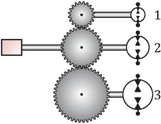
Figure 9 Illustration of how multiple HMs can be driven by the same prime mover with a mechanical gearing for the shaft speed of each HMs.
When mounting several HMs on the same shaft, their rotational speed are all equal. This means that all HMs that share the same shaft need to be displacement variable to enable full and independent flow control. Even though it theoretically would be possible to control one of the units purely by varying speed, this is not possible in practice: when the unit with only speed control has a requirement of zero flow, the shaft is stationary thus preventing all other units on the same shaft to control flow by displacement variability. Speed control could be added for the sake of minimizing losses, especially churning losses, and increased control capabilities at low flow requirements.
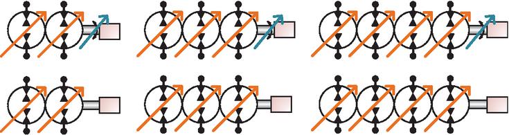
Figure 10 Illustration of how 2, 3, or 4 HMs can be driven by the same axle drive shaft.
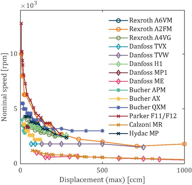
Figure 11 Relation between (maximum) displacement and maximum continuous (nominal) speed for various commercially available HMs (datasheet values).
Commercially available HMs have an inverse relation between nominal speed and displacement size when considering a certain flow. This is illustrated by Figure 11 showing the relation between datasheet values for nominal speed and displacement for various component series from multiple manufacturers. In the case of variable displacement machines, the shown displacement is the maximum displacement.
This relation entails that smaller HMs need to be driven to much higher speeds to exploit the full flow potential of the machine. Conversely, if a small machine is mounted on the same shaft as a large machine, the shaft speed is limited by the minimum of the nominal speeds. To compensate for the lower speed range, the smaller machine would need to be sized bigger to deliver the same flow. A way to compensate for the different speed ratings of different machines is to have the machines mechanically coupled through a gearing as exemplified by the illustration in Figure 9. This way, it is still possible to only use a single prime mover to power several HMs while the gearing can be chosen to match the speed characteristics of each HM. Figure 9 shows an illustration of how three HMs, driven by the same prime mover, are mechanically coupled through a gearing. Following the trend shown in Figure 11, and resulting in the flows as Equation 25, with being the number of teeth in the corresponding gear. The speed gearing is a fixed ratio, why full individual flow control must still be obtained by displacement and possibly speed variability, similar to the case where all HMs were mounted directly on the same drive shaft, having the same rotational speed.
| (18) |
In theory, it could be possible to implement a continuously variable transmission (CVT) gearing enabling a continuous control of the gearing ratios between shaft speed, which would make it possible to actively control the speed of each HM. This way, individual speed control is maintained, while using only a single prime mover, enabling the use of fixed displacement machines despite having a mechanical coupling.
4.2 Prime Movers
Here, prime movers are defined to be the power sources to HMs by converting an energy potential to mechanical energy on a shaft. The power flows in an HDN are interlinked as of the introduced coupling effects, though, on average, power is flowing from the prime movers to the actuators which are expected to perform work. Neglecting losses, power is maintained at every stage, why the total power is always the same, as implied in Equation 26 containing the dot product of torques and speeds (mechanical power), pressure differences and flows (hydraulic power), as well as forces and velocities (mechanical power).
| (19) |
Fluid short circuit connections enable pressurized fluid flow between actuator chambers and thus power to flow directly between actuators. The HMs that are connected between control volumes create flow couplings between these actuators and thus power is modulated as needed between the connected chambers.

Figure 12 Prime movers which can input mechanical power on a shaft driving HMs.
Figure 12 shows three types of prime movers which can deliver power to a drive shaft driving an HM, namely: hydraulic, electric, or fuel based prime movers. Without considering the specificities of each prime mover, any prime mover could deliver power to any shaft driving one or several HMs, thus satisfying the function as a power source. When analyzing a specific application, it is essential to consider the required dynamic performance of the hydraulic system and whether this can be achieved with some combination of HMs and prime movers. For example, the required range of dynamic performance differs greatly from a harbor crane to an injection molding machine. The applicability of different prime movers and other drive components must therefore be assessed for each individual application.
A hydraulic prime mover converts a hydraulic pressure potential from a pressure rail to mechanical power on a drive shaft. For a hydraulic prime mover the shaft torque and speed is controlled through the varying displacement of a hydraulic motor. Effective speed control of a shaft is thus dependent on the control mechanism for the motor displacement. For hydraulic prime movers, regenerative (negative) power may be shared through a pressure rail to other hydraulic prime movers and stored in an accumulator. Alternatively, excess pressure may be dissipated over a discharge valve connected to a hydraulic tank.
Electric machines convert an electric potential to mechanical power on the drive shaft. Considering electric prime movers such as e.g. electric synchronous motors combined with electric inverter drives, these generally have appropriate dynamic performance. For electric prime movers, regenerative power may be shared with other electric prime movers e.g., through a shared DC-bus, or the power may be stored on a capacitive element. Alternatively, regenerative power may be dissipated in break resistors or directed into the electric grid in the case of grid connected machines.
Internal combustion engines (ICEs) create mechanical power from a chemical potential. ICEs have a relatively slow dynamic response and can only turn in one direction and hence only have limited ability for speed control of their shaft. A hydraulic drive with a combustion engine as the prime mover would thus involve displacement control of the HMs and could include a mechanical flywheel to average out power spike demands on the combustion engine. A fuel powered prime mover is not able to regenerate power, so the only options are to convert the energy to another form, which requires extra components, or dissipate the energy in some form of brake. Here again, a flywheel could store smaller spikes of regenerative power. The downside of using a larger flywheel is that any speed changes (including startup) become more power intensive.
5 Conclusion
HDNs offer an interconnected approach to designing a multi-actuator hydraulic drive system without any conceptual losses. They are defined as incorporating hydraulic coupling mechanisms with the consequence that one flow input affects multiple actuators because of flow couplings through the connections of HMs in addition to fluid short circuit connections of actuator chambers.
Types of HMs and their requirements are showcased and discussed, with special focus on achieving independent (4-quadrant) flow control of each machine for ensuring proper control of drive networks. An example is presented employing transformer type HMs, which may be advantageous for minimizing the flow downstream in the hydraulic network. Mechanical couplings are discussed with consideration for the degrees of freedom of each drive. Multiple hydraulic displacement units may be driven by the same drive shaft, allowing these to be powered by the same prime mover. Alternatively, several shafts may be connected through a gearing (possibly variable) which may allow for a better exploitation of the HM speed capabilities when mechanically coupled units are of different sizes. Finally, prime movers and their potential for realizing speed control is discussed, as well as the power flows and handling of regenerative (negative) power flows.
HDNs encompass a vast design space of coupling mechanisms and components, all of which may be relevant when designing an optimal architecture with respect to objectives such as component sizes and efficiency. The optimal configuration depends heavily on the required actuator output movements and forces, as well as the availability and size resolution of components.
Given this complexity, identifying optimal configurations requires not only a clear understanding of system requirements but also further exploration of practical implementations. Future studies could explore HDN architectures using a single prime mover with variable displacement pumps, as well as assess how auxiliary and safety features, such as load holding, thermal management, and fault tolerance, can be integrated within HDNs.
References
[1] A. Vacca and G. Franzoni, Hydraulic fluid power : fundamentals, applications, and circuit design. Hoboken, NJ: Wiley, first edition ed., 2020.
[2] D. Hagen, D. Padovani, and M. Choux, “A comparison study of a novel self-contained electro-hydraulic cylinder versus a conventional valve-controlled actuator—part 1: Motion control,” Actuators, vol. 8, no. 4, 2019. https://doi.org/10.3390/act8040079.
[3] S. Michel and J. Weber, “Energy-efficient electrohydraulic compact drives for low power applications,” in Fluid Power and Motion Control FPMC 2012, Bath (GB), pp. 93–107, 2012.
[4] S. Frischemeier, “Electrohydrostatic actuators for aircraft primary flight control - types, modelling and evaluation,” in Proceedings of the 5th Scandinavian International Conference on Fluid Power, SICFP ’97, Linköping, Sweden, May 28. -30, pp. 1–16, Technische Universität Hamburg, 5 1997. https://doi.org/10.15480/882.236.
[5] S. Helduser, “Electric-hydrostatic drive—an innovative energy-saving power and motion control system,” Proceedings of the Institution of Mechanical Engineers, Part I, vol. 213, no. 5, pp. 427–437, 1999.
[6] Z. Quan, L. Quan, and J. Zhang, “Review of energy efficient direct pump controlled cylinder electro-hydraulic technology,” Renewable and Sustainable Energy Reviews, vol. 35, pp. 336–346, 2014. https://doi.org/10.1016/j.rser.2014.04.036.
[7] T. Koitto, H. Kauranne, O. Calonius, T. Minav, and M. Pietola, “Experimental study on fast and energy-efficient direct driven hydraulic actuator unit,” Energies, vol. 12, no. 8, 2019. https://doi.org/10.3390/en12081538.
[8] C. Schenke and J. Weber, “Energy efficiency of displacement control drive systems in hydraulic forming presses,” Journal of Manufacturing Science and Engineering, vol. 141, p. 041013, 02 2019. https://doi.org/10.1115/1.4042604.
[9] P. A. Achten and J.-O. Palmberg, “What a difference a hole makes-the commercial value of the innas hydraulic transformer,” in The Sixth Scandinavian International Conference on Fluid Power, SICFP’99, pp. 873–886, Tampere University of Technology, Finland, 1999.
[10] M. Heikkilä and M. Linjama, “Displacement control of a mobile crane using a digital hydraulic power management system,” Mechatronics, vol. 23, no. 4, pp. 452–461, 2013. https://doi.org/10.1016/j.mechatronics.2013.03.009.
[11] W. Shen, H. Huang, Y. Pang, and X. Su, “Review of the energy saving hydraulic system based on common pressure rail,” IEEE Access, vol. 5, pp. 655–669, 2017. https://doi.org/10.1109/ACCESS.2017.2648642.
[12] P. Johansen and A. H. Hansen, “A digital hydraulic full-bridge oscillation transformer,” in ASME/BATH 2023 Symposium on Fluid Power and Motion Control, Fluid Power Systems Technology, p. V001T01A055, 10 2023. https://doi.org/10.1115/FPMC2023-111865.
[13] P. Y. Li, J. Siefert, and D. Bigelow, “A hybrid hydraulic-electric architecture (hhea) for high power off-road mobile machines,” in ASME/BATH 2019 Symposium on Fluid Power and Motion Control, Fluid Power Systems Technology, p. V001T01A011, 10 2019. https://doi.org/10.1115/FPMC2019-1628.
[14] A. A. Khandekar, J. Siefert, and P. Y. Li, “Co-design of a fully electric hybrid hydraulic-electric architecture (fe-hhea) for off-road mobile machines,” in 2021 American Control Conference (ACC), pp. 352–357, 2021. https://doi.org/10.23919/ACC50511.2021.9482615.
[15] J. Siefert and P. Y. Li, “Optimal control of the energy-saving hybrid hydraulic-electric architecture (hhea) for off-highway mobile machines,” IEEE Transactions on Control Systems Technology, vol. 30, no. 5, pp. 2018–2029, 2022. https://doi.org/10.1109/TCST.2021.3131435.
[16] J. Wills and P. Y. Li, “Electric and hydraulic propel torque modulation for a compact track loader with the hybrid hydraulic electric architecture (hhea),” in ASME/BATH 2023 Symposium on Fluid Power and Motion Control, Fluid Power Systems Technology, p. V001T01A067, 10 2023. https://doi.org/10.1115/FPMC2023-112035.
[17] J. Wills and P. Y. Li, “Comparison of real-time pressure rail selection algorithms for the hybrid hydraulic electric architecture: Case study on a track loader,” in BATH/ASME 2024 Symposium on Fluid Power and Motion Control, Fluid Power Systems Technology, p. V001T01A027, 09 2024. https://doi.org/10.1115/FPMC2024-140443.
[18] L. Schmidt and K. V. Hansen, “Electro-hydraulic variable-speed drive networks; idea, perspectives, and energy saving potentials,” Energies, vol. 15, no. 3, 2022. https://doi.org/10.3390/en15031228.
[19] L. Schmidt and M. van Binsbergen-Galán, “Electro-hydraulic variable-speed drive network technology—first experimental validation,” Energies, vol. 17, no. 13, 2024. https://doi.org/10.3390/en17133192.
[20] L. Schmidt, M. van Binsbergen-Galán, R. Knöll, M. Riedmann, B. Schneider, and E. Heemskerk, “Energy efficient excavator implement by electro-hydraulic/mechanical drive network,” International Journal of Fluid Power, vol. 25, p. 413–438, Dec. 2024. https://doi.org/10.13052/ijfp1439-9776.2541.
[21] L. Schmidt, S. Ketelsen, and K. V. Hansen, “Perspectives on component downsizing in electro-hydraulic variable-speed drive networks,” in BATH/ASME 2022 Symposium on Fluid Power and Motion Control, Fluid Power Systems Technology, p. V001T01A027, 09 2022.
[22] M. van Binsbergen-Galán and L. Schmidt, “Characterization & identification of short circuit connections in hydraulic drive networks,” International Journal of Fluid Power, 2025. (in press).
[23] M. van Binsbergen-Galán and L. Schmidt, “Defining the design space of basic hydraulic drive networks,” International Journal of Fluid Power, vol. 26, no. 3, pp. 1–20, 2025. (in press).
Biographies

Mikkel van Binsbergen-Galán received his M.Sc. degree in engineering (mechatronics) from Aalborg University in 2022. He is currently a Ph.D. Fellow at AAU Energy, Aalborg University, working with the design of drive systems for mechatronic systems with a special focus on hydraulic systems and the components associated with such systems.

Lasse Schmidt received the M.Sc. degree in engineering (mechatronics) from Aalborg University, Denmark, in 2008. From 2008 he was with the application engineering group of Bosch Rexroth A/S, Denmark, and from 2010 an industrial Ph.D. fellow also associated with Aalborg University. He received the Ph.D. degree in robust control of hydraulic cylinder drives in 2014. Subsequently, he has been a postdoctoral researcher at AAU Energy while concurrently being with Bosch Rexroth AG. Hereafter he became an Assistant Professor with AAU Energy. He is currently an Associate Professor with AAU Energy and heading research activities related to electro-hydraulic drive network technology, a field in which he is the founder of the fundamental design and control principles. He is the main author or co-author of nearly 70 scientific peer-reviewed publications, most of them on topics related hydraulic drives and systems control. Lasses current research interests are in design and control of electro-hydraulic drive networks and their integration into both mobile working machines and industrial systems.
International Journal of Fluid Power, Vol. 27_3, 487–510
doi: 10.13052/ijfp1439-9776.2731
© 2026 River Publishers