A Coupled Elastohydrodynamic Lubrication Model for Radial Piston Motors Incorporating Piston Tilt and Deformation
Jinhwan Lee1,*, Lizhi Shang1,* and Pierre Bernard2
1Maha Fluid Power Research Center, Purdue University, Lafayette, IN, USA
2Poclain Hydraulics Industrie, Verberie, France
E-mail: lee4775@purdue.edu; lshang@purdue.edu; pierre.bernard@poclain.com
*Corresponding Authors
Received 30 August 2025; Accepted 15 December 2025
Abstract
This study presents a coupled Elastohydrodynamic Lubrication (EHL) simulation model for a multi-lobe radial piston motor and its experimental validation under high-load and low-speed conditions. These operating regimes pose challenges such as severe wear and excessive power loss due to complex lubricating interfaces, which are difficult to characterize experimentally. To address this, the model solves a density-based Reynolds equation incorporating multi-body dynamics, throttling losses, and elastic deformations of components. Simulation results reveal that lubrication regimes and asperity contact pressures depend strongly on chamber pressure and motor speed. The roller–bushing interface operates under mixed lubrication, while the piston–cylinder interface exhibits boundary lubrication during high-load conditions due to severe asperity contact. Piston tilt and asymmetric deformation significantly affect film thickness and pressure distribution of lubricating interfaces. Incorporating a friction model based on experimental data enabled a realistic analysis of power loss, identifying the upper piston–cylinder interface and throttling loss as major contributors. The model provides a detailed framework for simulating and analyzing tribological behaviors in radial piston motors and can be used to evaluate the effects of design parameters such as clearance, geometry, and material properties.
Keywords: Radial piston motors, elastohydrodynamic lubrication, deformation, power loss.
1 Introduction
A multi-lobe radial piston motor offers high-torque actuation in a hydraulic transmission for construction and agricultural machinery. Radial piston motors convert the flow energy from pressurized inlet fluid into mechanical shaft work through piston strokes. In this process, a hydrostatic force is transferred through a series of components – cam, roller, bushing, piston, and cylinder bore wall – via lubricating interfaces. The hydrostatic pressure applied to the piston is balanced by the normal force from the cam with a certain contact angle, causing the piston to exert force on the cylinder wall and generate torque. More details on the working principle of radial piston motors can be found in [1, 2].
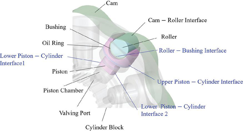
Figure 1 Lubricating interfaces.
Tribological performance of the lubricating interfaces can substantially affect the overall efficiency and reliability of radial piston motors. There are multiple lubricating interfaces for a typical stepped piston assembly as described in Figure 1. The cam–roller interface is a nonconformal rolling contact with relatively negligible power loss, and the roller–bushing interface is a crucial conformal contact which should provide reliable low friction. Also, the connected upper and separate lower bore interfaces are piston–cylinder interfaces that do not have reliable pressure build-up mechanisms due to piston tilt. Radial piston motors typically operate at low speeds and high loads, and these operating conditions have the potential to result in excessive power loss due to increased solid friction from asperity contact and mechanical failure from surface damage.
Many experimental research works focused on improving the overall performance of the lubricating interfaces by reducing frictional coefficient and surface damage. Olsson et al. [1] used a simulated test bench to investigate the effect of lubricant properties on tribological behaviors of a piston–cylinder interface, assuming a rectangular contact area. Pettersson et al. [3] showed that the textured surfaces of a roller–piston interface could improve friction coefficient variation. Lewis [4] studied the effect of surface layer material on friction coefficient and scuffing damage with different lubricant supply conditions and demonstrated lower friction coefficient with cloth material than sintered bronze. Nilsson et al. [5] studied seizure mechanisms of a radial piston motor under actual motor operation conditions using a test configuration that can measure hydromechanical losses. They demonstrated that seizure could initiate from a roller–piston interface and piston–cylinder interface with increased hydromechanical loss, severe wear, and scuffing. A drawback with the above-mentioned works is that their results may not exactly represent the motor operation condition because the lubricating interfaces were investigated in isolation with simplified test setups in which lubricating conditions might be different [1, 3, 4]. Also, experimental studies may need bulky and high-cost test rigs that cannot be easily configurable for different machine designs. Above all, it is difficult to directly measure important physical quantities such as hydrodynamic pressure, asperity contact pressure, and film thickness.
To address those difficulties, many numerical models were proposed to understand the behaviors of lubricating interfaces in hydraulic machines. Dahlén et al. [6] proposed a full film lubrication model for the roller–bushing interface and valving interface in a radial piston motor by solving a Reynolds equation. Isaksson et al. [7, 8] proposed a full film and mixed lubrication model for the roller–piston interface with a hydrostatic groove, considering the piston deformation and surface roughness. Zhang et al. [9] proposed the unsteady EHL model for a roller–piston interface and showed that a slotted hole could largely increase the film thickness. Zhang et al. [10] proposed a modified lubrication model for a roller–piston interface with a focus on thermal analysis, demonstrating a significant temperature rise from viscous and asperity friction. Li et al. [11] proposed a CFD simulation for a valving interface with leakages and volumetric efficiency analysis. Besides simulation models for radial piston motors, advanced coupled simulation models have been developed for other types of hydraulic machines. Ransegnola et al. [12] proposed a simulation model that considered multiple lubricating interfaces in a swashplate-type axial piston machine to investigate piston and slipper spin. Sarode et al. [13] used a simulation model to investigate the effect of geometric tolerance and taper of a piston on energy dissipation in piston-cylinder interface of an axial piston machine. Mukherjee et al. [14] developed a coupled thermal simulation model to study the effect of thermal behaviors on the efficiency and film thickness in a swashplate-type axial piston machine. Also, Pawar et al. [15] proposed a coupled thermal simulation model for an external gear machine that can predict housing wear and efficiency. Ivantysyn et al. [16] presented a comprehensive study on developing a digital twin of an axial piston machine and showed that the simulation model can be used to predict overall performance and lifespan of the machine.
To date, a fully coupled EHL simulation model for a radial piston motor that incorporates multiple physical phenomena – such as transient chamber pressure, lubricating interfaces, asperity contact, rigid body dynamics, and component deformation – has not been developed. Previous numerical studies have typically neglected critical aspects of piston dynamics, such as tilt during operation, which significantly influence asperity contact pressure and area. Additionally, the coupled interaction between the roller–bushing and piston–cylinder interfaces has often been overlooked due to modelling complexity, despite their substantial combined impact on piston deformation and dynamics. As a result, despite extensive experimental and simulation efforts, the design of lubricating interfaces in radial piston motors remains challenging, largely due to limited understanding of their coupled behaviors. The purpose of this study is to develop and validate a coupled EHL simulation model that can assess various design parameters and provide physical insights into tribological behavior incorporating important physics.
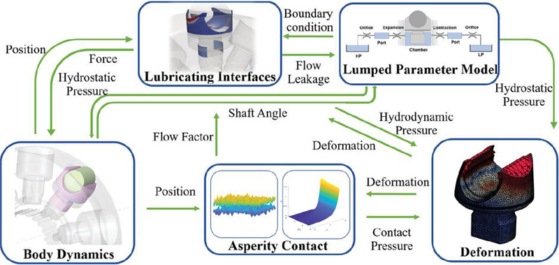
Figure 2 Simulation domains.
Universal Reynolds equations for the roller–piston interface and piston–cylinder interfaces are fully coupled with the lumped parameter model, rigid body dynamics, and deformation caused by hydrodynamic and asperity contact pressures. The physical quantities exchanged between different physical domains are illustrated in Figure 2. The simulation was performed using Multics, an in-house numerical solver for hydrostatic machines developed by the authors’ research group. To validate the developed simulation model, experimental measurements were conducted for the roller–bushing interface as well as all lubricating interfaces, including the piston–cylinder interface. A commercially available MSE08 motor from Poclain Hydraulics Industrie, with a maximum displacement of 1248 cc and a rated power of 41 kW, was selected as the reference machine. The working fluid used was ISO VG46, and isothermal conditions at 50∘C were assumed to represent typical operating conditions. Simulations were carried out over a range of shaft speeds from 30 RPM to 150 RPM, with inlet pressures varying from 50 bar to 350 bar, and a fixed outlet pressure of 20 bar.
This study is an extended version of our previous work presented in SICFP 2025. While the experimental comparison was included in the earlier version, the discrepancy with simulation motivated the development of realistic friction model, which improves the correlation with measurement. The developed model is newly validated for 150 RPM and the power loss analysis has been updated.
2 Numerical Models
2.1 Lumped Parameter (LP) Model
The LP model is crucial to the entire simulation because it calculates the piston chamber pressure, which other domain solvers rely on, and the throttling loss, another major source of the power losses. The cross-section view of a piston with the valving interface and its equivalent hydraulic circuit are presented in Figure 3. As the cylinder block rotates, the port is alternatively connected to the high-pressure inlet and low-pressure outlet. When the port connects to the high-pressure inlet, the piston moves upward, increasing the piston chamber volume; when it connects to the low-pressure outlet, the piston moves downward. The inlet and outlet of the port are where the throttling losses occur, and any flow leakage or friction loss through the valving interface was not considered in the simulation.
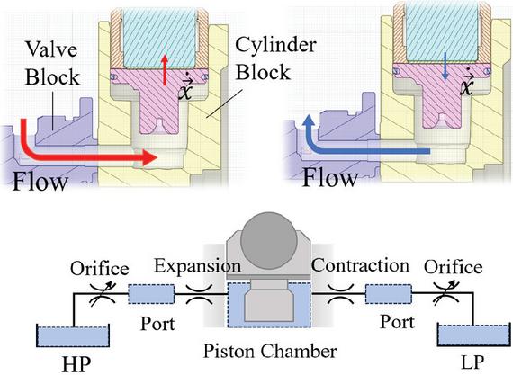
Figure 3 Hydraulic circuit for the LP model.
While a computationally cost-effective and reasonably accurate model to calculate pressure for a control volume, such as a piston chamber and port is the pressure build-up equation (Equation (1)) where , and represent volume averaged pressure, isothermal bulk modulus, and chamber volume.
| (1) |
Also, the volume flow in Equation (1) depends on the opening area of the valving port and the pressure difference , and this can be modeled as flow with a restrictive orifice (Equation (2)). and represent orifice discharge constant and averaged density of the fluid.
| (2) |
In addition to the throttling loss, the expansion and contraction of the flow path may provide additional pressure drop, as modeled in Equation (3). and , , , and represent minor loss coefficient, Darcy friction coefficient, port length, port diameter, and averaged flow velocity respectively.
| (3) |
Since the orifice opening area and volume change are function of a motor shaft angle, Equations (1), (2) and (3) should be solved simultaneously with body dynamics.
2.2 Lubricating Interfaces
The hydrodynamic pressure of the lubricating interfaces can be calculated using the density-based universal Reynolds equation for a mixed lubrication suggested by Ransegnola [17] where , , and represents pressure flow factor, shear flow factor, contact flow factor, and roughness flow factor in Equation (4). The equation considers the effect of asperity contact on hydrodynamic pressure by introducing the concept of averaged flow using flow factors. The pressure flow factor represents increased resistance from asperity for pressure-driven Poiseuille flow and shear flow factor represents added shear flow caused by asperity [18, 19]. Also, contact flow factor and roughness flow factor are used to relate averaged film thickness with local film thickness for compressible flow [17, 20]. Those flow factors can be pre-calculated for nondimensional film thicknesses assuming Gaussian and isotropic surface roughness, and the results can be found in [17].
| (4) |
2.3 Asperity Contacts
In mixed or boundary lubrication regimes, the asperity contact pressure provides additional load support for a lubricating interface. Lee et al. [21] provided the curve-fitted analytic model that can predict averaged asperity contact pressure for given material properties and fluid film thickness, considering the elastic and plastic behavior of surfaces (Equation (5)). The surface roughness was measured for all lubricating surfaces, and the equivalent surface roughness were used for Equation (5) and flow factor calculations for each lubricating interface. As a results, the friction force that includes hydrodynamic shear stress [18] and asperity contact friction can be calculated as Equation (6). In addition, the measured surface profile of the roller from partial crowning which is known to prevent high stress at the edges was implemented to provide an additional gap height to the edges.
| (5) | |
| (6) |
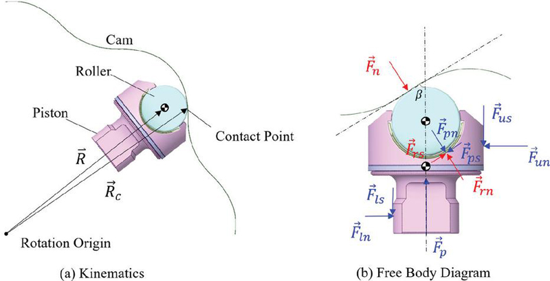
Figure 4 Roller and piston dynamics.
2.4 Kinematics and Rigid Body Dynamics
As shown in Figure 4(a), the rotational velocity of the roller can be obtained by assuming no slip at the contact point, which means the velocity at the contact point should be zero (Equation (7)). The calculated rotational velocity was imported as a look-up table which is a function of a cylinder block rotation angle.
| (7) |
The free-body diagram for the piston and roller is shown in Figure 4(b). The forces applied to the roller are represented in red and the forces applied to the piston are represented in blue. The pressure force is calculated from the piston chamber pressure in the LP model. The normal force represents the reaction force from the contact point and can be approximated from force balance using contact angle without considering friction from the piston-cylinder interfaces. and , are shear and normal force applied to the roller by the roller–bushing interface, and and are shear and normal force applied to the piston by the same lubricating interface. Similarly, and are shear and normal force applied to the piston by upper piston–cylinder lubricating interface, and and are shear and normal force applied to the piston by the lower piston–cylinder lubricating interfaces. Also, the cylinder block was set to rotate at a constant shaft speed. Since the motion in axial direction is constrained by a thrust bearing and the valving interface, only planar motions were considered for the roller and piston with Newton’s second law (Equations (8 and 9)).
| (8) | ||
| (9) |
2.5 Solid Deformation
In general, deformation considerably affects hydrodynamic pressure and film thickness distribution in an elastohydrodynamic lubrication. Moreover, the roller–bushing interface and the piston–cylinder interface have a mutual effect on the overall deformation of the piston. One of the most successful methods to consider deformation for a Reynolds equation is the influence matrix method [22]. By solving a linear static elastic equation offline using a finite element method, the relationship between the deformation gap for th node and reference pressure on th face in fluid film domains is found in matrix as Equation (10). Then, the matrix operation is performed in the main coupled simulation for combined pressure which includes hydrostatic, hydrodynamic, and asperity contact pressure for j-face in fluid films. To generate the influence matrix for each solid body, the mechanical properties of standard alloy steel were used for the roller, piston, and cylinder block, and the equivalent mechanical property was used for PEEK-based bushing.
| (10) |
3 Experimental Validation
3.1 Experimental Setup
The friction torque from the simulated lubricating interfaces was compared to measurement using an experimental setup with a torque meter (Figure 5). To isolate frictions from other sources of power loss, the electric motor rotates the cam through a shaft supported by two bearing supports while pressurized fluid is supplied to the inlet of the fixed cylinder block. During the measurement, the chamber pressure was controlled to increase slowly. This experimental setup is different from actual motor operating conditions where cylinder block ports are alternatively connected to valve block ports and pressurization and depressurization of chamber pressure occur. Additionally, ISO VG46 was used as the working fluid, and the temperature of the cylinder block was controlled to around 50∘C by an external cooling system. PT100 resistance temperature detector was installed to measure fluid temperature with an accuracy of 1.5∘C. For all measurements, the torque meter was calibrated to eliminate the friction torque from the bearing supports, providing an accuracy of 2.5Nm.
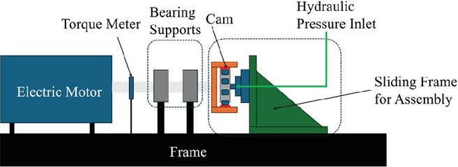
Figure 5 Schematic diagram for experimental setup.
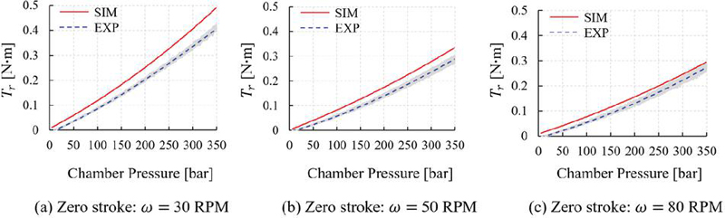
Figure 6 Roller friction torque comparisons.
3.2 Friction Torque Comparison
First, a zero-stroke cam without a wavy profile was used to prevent reciprocating motion of the piston where only friction from the roller–bushing interface was measured. The measurement inevitably includes the friction from roller – cam interface, but the amount may be negligible when assuming pure rolling. The measured friction torque from the shaft can be related to simulated roller friction torque using Equations (11 and 12) where , , , and represent the power loss, number of rollers, shaft speed, roller speed, and and represent the diameter of the cam and roller.
| (11) | |
| (12) |
Similar to the experiment, the inlet pressure and resultant force applied were increased gradually for different shaft speeds during the simulation. A constant friction coefficient of 0.006 was used for asperity contact in the roller–bushing interface, and the total friction is the sum of viscous and asperity contact frictions (Equation (6)). The measurement and simulation results showed a relatively good match in trends (Figure 6(a, b, c)) although the growing deviation can be observed for high chamber pressure at 30 RPM, which can be attributed to nonlinear asperity contact behavior at this condition.
Second, the full-stroke cam with a wavy profile was used to measure the friction from all lubricating interfaces, including the roller–bushing interface and piston–cylinder interfaces. Unlike the previous case for the zero-stroke cam with the gradual pressure increase, the simulation was run for 12 operating conditions with fixed chamber pressure due to high computational costs. The power loss from the piston–cylinder interfaces was much greater than that from the roller–bushing interface, and mostly due to asperity contact friction. Moreover, the asperity friction coefficient for piston–cylinder interface highly depended on the operating conditions, ranging from 0.06 to 0.15.
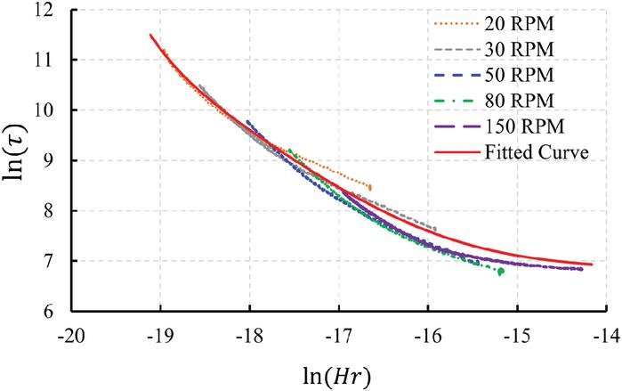
Figure 7 Dimensionless friction torque and operating conditions.
To obtain a realistic friction model from experimental data, a dimensionless analysis by the Buckingham Pi theorem [23] was introduced to generalize the effect of operating conditions on the friction torque. The averaged friction torque can be a function of various parameters from geometric dimensions, material properties of solid parts and working fluid, and operating conditions (Equation (13)).
| (13) |
Choosing viscosity , cam diameter , and rotational speed as scaling variables yields the dimensionless torque number where represents order of magnitude of the viscous torque applied to the cam or cylinder block depending on kinematics (Equation (14)).
| (14) |
Under varying operating conditions for the same machine, the dimensionless geometric parameters remain constant and can therefore be considered negligible in their influence. Similarly, the effect of dimensionless material properties has been found to be minimal. Instead, friction torque shows a strong dependence on dimensionless operating conditions, , similar to the Hersey number used in the Stribeck curve for journal bearing lubrication [24], which distinguishes different lubrication regimes (Equation (3.2)). In this context, a lower value of indicates more severe asperity contact between the piston–cylinder interfaces, leading to increased friction torque.
| (15) |
The dotted lines in Figure 7 represent the measured dimensionless friction torque at rotational speeds of 20, 30, 50, 80, and 150 RPM. The experimental correlation (solid red curve) was derived using the data at 20, 30, 50, and 80 RPM, excluding 150 RPM. The data at 150 RPM was used as an independent validation to demonstrate the capability of the method to predict friction torque for general operating conditions. Therefore, for any given operating condition, the friction torque can be predicted using the experimental correlation. Furthermore, the solid friction coefficient can be estimated through power loss calculations, under the reasonable assumption that asperity contact friction dominates over viscous friction in the piston–cylinder interface (Equation (16)).
| (16) |
The calibrated simulation results for 30, 50, and 80 RPM showed close agreement with experimental measurements. The developed model was further validated at 150 RPM, demonstrating a similar level of relative error (Figure 8).
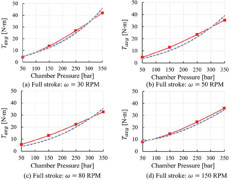
Figure 8 Total friction torque comparisons.
4 Results and Discussion
Unlike the experimental set up where the chamber pressure is slowly increased or maintained, the simulation results in this section considers transient chamber pressure and valving port timing by solving the lumped parameter model.
4.1 Roller – Bushing Interface
The fluid films are strongly coupled through piston dynamics and deformation and this coupling significantly affects hydrodynamic and asperity contact pressures and fluid film thickness distribution. This is especially important when the contact angle is at the maximum and the piston exerts a maximum force on the cylinder wall, and as a result, the piston deforms asymmetrically (Figure 9). This asymmetric deformation results in tribological behavior that differs from previous observations, where the minimum film thickness is typically observed in the middle of the lubricating area [10]. The hydrodynamic pressure and film thickness distribution of the roller–bushing interface at this moment are illustrated in Figures 10 and 11. The x-axis represents the roller coordinate angle at the mid-plane of the interface, and the y-axis represents the corresponding dimensionless film thickness and hydrodynamic pressure. The minimum yield strength of two surfaces used to nondimensionalize hydrodynamic and contact pressure were 120 MPa for roller–bushing interface and 240 MPa for piston–cylinder interface. In the asperity-contact model the nominal hardness is assumed to be three times the minimum yield strength [21]; using for scaling therefore gives a physically meaningful measure of pressure relative to nominal hardness. In addition, the asperity contact mainly occurs from 60∘ to 180∘, those regions are plotted in magnified view on the upper right-hand side of each figure.
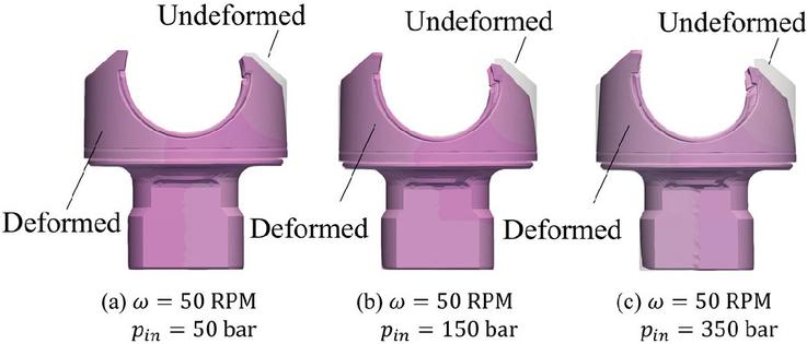
Figure 9 Deformation of piston (exaggerated).
At shaft speeds of 80 RPM and 150 RPM, the roller rotates rapidly enough to develop adequate hydrodynamic pressure across the lubricated area, except near the bushing edge (Figures 10(c), (d) and 11(c), (d)). Under these conditions and an inlet pressure of 50 bar, the minimum dimensionless film thickness exceeds 1, indicating operation in the partial lubrication regime [24]. However, at higher inlet pressures – 150, 250, and 350 bar – the asymmetric piston deformation has a more pronounced impact. Near the roller edge (180∘), the film thickness significantly decreases, accompanied by a localized spike in hydrodynamic pressure and the onset of asperity contact. This behavior is consistent with the experimental findings of Nilsson et al. [5], who reported severe wear near the piston edge. Interestingly, the same asymmetric deformation can locally enhance the film thickness in other regions. This effect is particularly evident in the area between 90∘ and 150∘, where increased inlet pressure results in a measurable rise in film thickness.
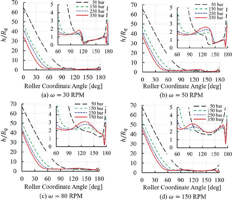
Figure 10 Film thickness distribution on roller–bushing interface.
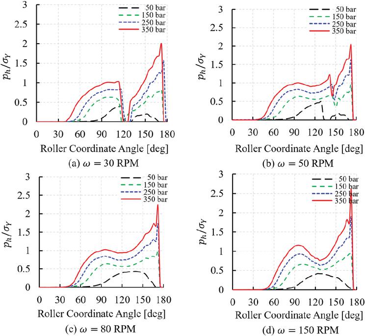
Figure 11 Hydrodynamic pressure distribution on roller–bushing interface.
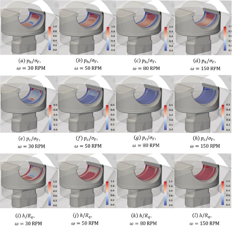
Figure 12 Roller–bushing interface results for bar.
Moreover, when the shaft speed further decreased from 80 RPM to 50 RPM, the loss of hydrodynamic pressure induced more asperity contact before the roller coordinate angle of 150∘ (Figures 11(b) and 12(b), (f), (j)). This behavior is even more pronounced when the shaft speed is 30 RPM, showing a complete loss of hydrodynamic pressure around 120∘ for all inlet pressure conditions (Figures 11(a) and 12(a), (e), (i)). The film thickness remained relatively constant due to the severe solid contact, and this eliminated the primary hydrodynamic pressure build-up mechanism, physical wedge from the geometrical nominal clearance. These results demonstrated the tribological behaviors of the roller–bushing interface is highly sensitive to the operating conditions, and high loading and low shaft speed can pose wear or seizure as observed in [5].
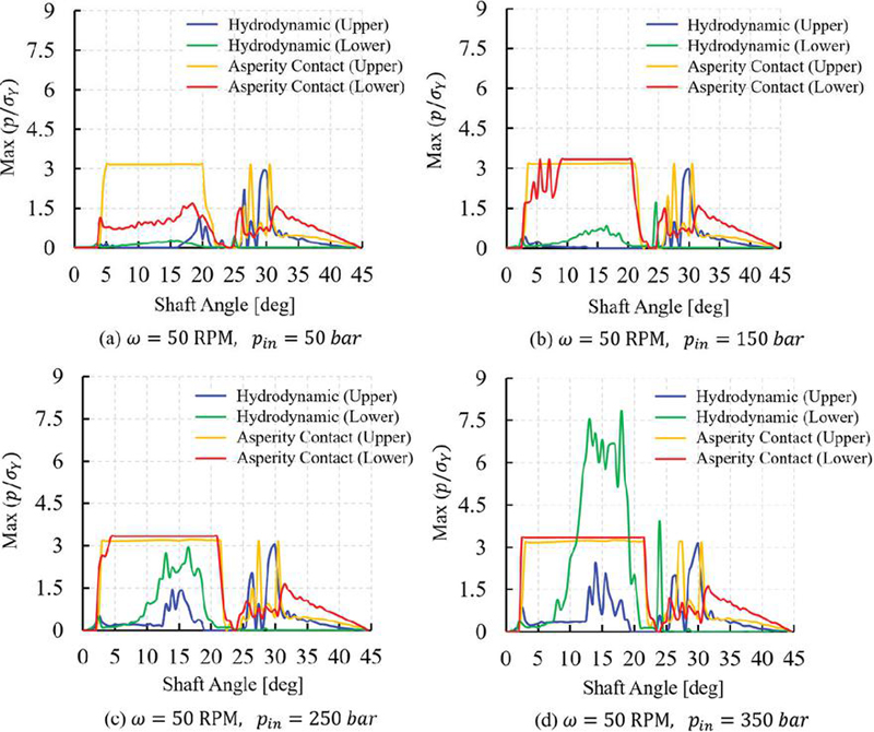
Figure 13 Maximum dimensionless hydrodynamic and contact pressure.
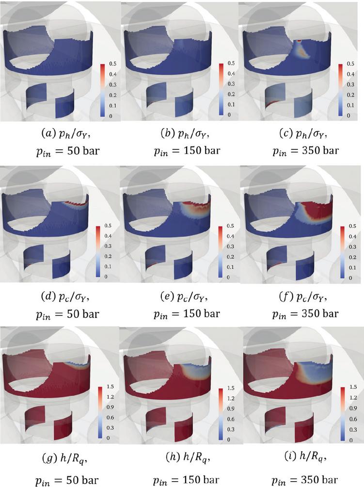
Figure 14 Piston–cylinder interface for RPM at the shaft angle of 13∘.
4.2 Piston–cylinder Interface
When the contact angle is not zero, the geometrical nominal clearance between a piston and cylinder bore can induce tilt of the piston which can largely influence the hydrodynamic and contact pressure distribution on the piston–cylinder interfaces. To investigate those behaviors, the maximum value of hydrodynamic and asperity contact pressures over each interface domain for a period of reciprocating motion are shown for the shaft speed of 50 RPM with different inlet pressures (Figure 13). From 0∘ to 22.5∘ shaft angle, the piston chamber is connected to a high-pressure inlet, and the piston starts to move upward, tilt in the clockwise direction. This tilting of the piston offers a physical wedge only for the lower lubricating films, and the upper fluid film should rely on squeeze motion to build up hydrodynamic pressure. Therefore, the asperity contact pressure of the upper fluid film rapidly increased to hardness value and supported most of the loading for all inlet pressure conditions (Figure 14(d), (e), (f)). For these conditions, it should be noted that the hydrodynamic pressure only temporarily existed up to the shaft angle of 13∘ due to increased squeeze motion, and the pressure spikes from the shaft angle of 13∘ to 22.5∘ originated from a few isolated cells which cannot contribute much to the load support (Figure 14(c)). On the other hand, the lower fluid films can build up hydrodynamic pressure from the physical wedge, showing a significant increase in the high loading (Figure 13(d) and Figure 14(c)). However, the asperity contacts also occurred for lower films because the hydrodynamic alone cannot support the loading, and this asperity contact is highly dependent on the loading (Figure 14(d), (e), (f)). When the piston chamber is connected to the low-pressure outlet of 20 bar which corresponds to 22.5∘ to 45∘ shaft angle, the piston moves downward. The counterclockwise tilt of the piston provides the physical wedge only to the upper fluid film. Therefore, the maximum hydrodynamic pressure of the upper fluid film was higher when the piston moved downward than when the piston moved upward despite the much smaller loading. On the other hand, the lower fluid films cannot build up hydrodynamics pressure, and most of the loading is supported by asperity contact pressure. The region of high asperity contact pressure (100 bar) during the reciprocating motion is illustrated in Figure 15(a), (b), (c) for various shaft speed and inlet pressure conditions. The predicted area was compared to the wear area of a piston under real motor operating conditions and showed a good match in the location.
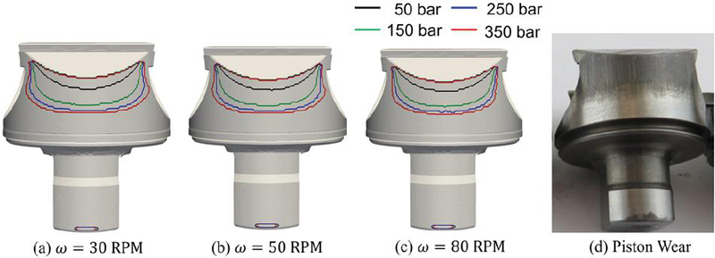
Figure 15 Asperity contact area and piston wear.
4.3 Power Loss Analysis
The ratio of power loss to theoretical power (Equation 17) was calculated to identify power loss contributions as shown in Figure 16.
| (17) |
The upper fluid film accounts for the majority of power loss across the lubricating interfaces, contributing more than 74% to 90% of the total power loss. This is consistent with the earlier discussion, as the upper film experiences significant asperity contact and wear. Although the trends in the power loss vary with shaft speed, they generally align with the dimensionless results shown in Figure 7. For instance, at 50 bar, power loss increases rapidly with shaft speed. In contrast, at 350 bar, a slight decrease in power loss is observed. On the x-axis of Figure 7, the 350 bar condition (ranging from 18.2 to 16.6) shows a steep drop in dimensionless torque, which corresponds to a slight reduction in actual torque. Conversely, the 50 bar condition (ranging from 14.5 to 16.3) exhibits a more gradual decline in dimensionless torque, resulting in an overall increase in actual torque. In most cases, the lower fluid films contribute negligibly to total power loss. This is due to their ability to generate hydrodynamic pressure during the upstroke and the comparatively lower load they bear. The roller–bushing interface contributes less than 1.5% to total power loss, owing to its consistent hydrodynamic support and the low solid friction coefficient between the PEEK-based bushing and the steel roller.
Beyond the lubricating interfaces, the developed model also predicts power losses associated with throttling, as captured by the LP model. These losses are caused by viscous dissipation occurring at the valving interface and internal flow connection to the chamber due to expansion and contraction. Throttling losses due to the valving interface, modelled as orifice flow, represent another significant source of power loss, particularly at high shaft speeds. When the inlet pressure increased from 50 bar to 150 bar, the throttling loss ratio decreased by approximately 60% at 80 RPM and 70% at 150 RPM. This behavior is likely due to the increased pressure difference between the inlet and the piston chamber, which may result in more complete chamber filling and shorten the duration of pressure drop. However, when the inlet pressure was further increased to 250 and 350 bar, the throttling loss ratio increased again. At sufficiently high inlet pressures, the chamber fills more completely, and the resulting higher flow velocities across the orifice induce greater viscous dissipation, thereby increasing throttling losses. The throttling losses due to the chamber connection were generally negligible across most operating conditions, with a maximum loss ratio of approximately 4% observed at low inlet pressure (50 bar) and high shaft speed (150 RPM).
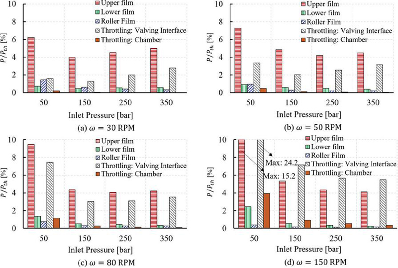
Figure 16 Power loss analysis.
5 Conclusion
A novel simulation framework was developed to investigate the lubricating interfaces in a radial piston motor. The model integrates a lumped parameter model with body dynamics, fluid-film lubrication, asperity contact, and elastic deformation in a fully coupled manner. Incorporating these multiphysics interactions was found to be essential for realistic predictions. The results showed that asymmetric deformation strongly influenced the hydrodynamic pressure and film thickness distribution in the roller–bushing interface. In addition, piston tilting introduced squeeze-film effects and wedge formation in the piston–cylinder interface, depending on the tilt direction. A comprehensive power loss analysis was performed across all lubricating interfaces and hydraulic components within the lumped parameter framework. Among them, the upper piston–cylinder interface was identified as the dominant loss source, followed by throttling losses at the valving interface under all operating conditions. Overall, the developed model provides a useful tool for assessing key design parameters such as nominal clearance, piston geometry, cam profile, and valving port area and timing, while also offering deeper insights into the lubricating behavior of piston–cylinder assemblies in radial piston motors.
Furthermore, significant power loss may raise the temperature of the entire radial piston motor, including the lubricating interfaces. Due to a decrease in viscosity, the performance of the lubricating interfaces may be highly affected. To account for thermal effects, the current model can be extended to include thermal aspects as a future work. The model should consider temperature distribution in the lubricating interfaces and heat conduction through adjacent solid parts with proper boundary conditions. The comparison between the current isothermal and thermal models will clearly reveal the thermal effects.
Nomenclature
| Symbol | Description | Symbol | Description |
| Orifice area | Asperity contact pressure | ||
| Nominal clearance | Hydrodynamic pressure | ||
| Orifice discharge coefficient | Inlet pressure | ||
| Piston Diameter | Pressure on th face | ||
| Port diameter | Reference pressure | ||
| Cam diameter | Power loss | ||
| Roller dimeter | Theoretical power | ||
| Darcy friction factor | Linear momentum | ||
| Force | Volume flow rate | ||
| Total friction force for lubricating interface | Equivalent surface roughness | ||
| Polynomial coefficient matrix | Roller position | ||
| Local fluid film thickness | Contact position | ||
| Deformation gap of ith node | Piston stroke period | ||
| Averaged fluid film thickness | Averaged shaft friction torque | ||
| Hersey number | Roller friction torque | ||
| Bulk modulus | Shaft friction torque | ||
| Port length | Flow velocity magnitude | ||
| Moment | Bottom surface velocity | ||
| Number of rollers | Mean velocity of two surfaces | ||
| Pressure | Top surface velocity | ||
| Displacement of piston chamber | Torque number | ||
| Roller linear velocity | Contact flow factor | ||
| Contact point velocity | Shear stress factors | ||
| Isotropic index parameter | Pressure flow factor | ||
| Minor loss coefficient | Roughness flow factor | ||
| Viscosity of a working fluid | Shaft speed | ||
| Contact friction coefficient | Roller angular speed | ||
| Density of a working fluid | Influence matrix | ||
| Minimum yield strength of two surfaces |
References
[1] H. Olsson, J. Ukonsaari, Wear testing and specification of hydraulic fluid in industrial applications, Tribology International, 36(11): 835–841, 2003, https://doi.org/10.1016/S0301-679X(03)00101-4.
[2] C. Zhang, H. Tan, Y. Fang, X. Zhang, Y. Yang, Y. Duan, M. Han, S. Cui, B. Xu, J. Zhang, Deformation pre-compensated optimization design of cam ring for low pulsation hydraulic motors, Journal of Zhejiang University SCIENCE A, 24(2) 130–145, 2023, https://doi.org/10.1631/jzus.A2200552.
[3] U. Pettersson, S. Jacobson, Textured surfaces for improved lubrication at high pressure and low sliding speed of roller/piston in hydraulic motors, Tribology International, 40(2): 355–359, 2007, https://doi.org/10.1016/j.triboint.2005.11.024.
[4] R. Lewis, Friction in a hydraulic motor piston/cam roller contact lined with PTFE impregnated cloth, Wear, 266(7–8): 888–892, 2009, https://doi.org/10.1016/j.wear.2008.12.009.
[5] D. Nilsson, B. Prakash, Investigation into the seizure of hydraulic motors, Tribology International, 43(1–2): 92–99, 2010, https://doi.org/10.1016/j.triboint.2009.05.001.
[6] L. Dahlén, H. Olsson, Analysis of two sliding contacts inside a radial piston hydraulic motor, Proceedings of the JFPS International Symposium on Fluid Power 2002, (5–2): 537–542, 2002, https://doi.org/10.5739/isfp.2002.537.
[7] P. Isaksson, D. Nilsson, R. Larsson, Elasto-hydrodynamic simulation of complex geometries in hydraulic motors, Tribology International, 42(10): 1418–1423, 2009, https://doi.org/10.1016/j.triboint.2009.05.018.
[8] P. Isaksson, D. Nilsson, R. Larsson, and A. Almqvist, The influence of surface roughness on friction in a flexible hybrid bearing, Proceedings of the Institution of Mechanical Engineers, Part J: Journal of Engineering Tribology, 225(10):975–985, 2011, https://doi.org/10.1177/13506501114172.
[9] X. Zhang, J. Zhang, B. Xu, Z. Yang, Q. Zhao, H. Zhang, The effect of slotted hole on minimum oil film thickness of piston in radial piston hydraulic motor, Proceedings of the ASME/BATH 2021 Symposium on Fluid Power and Motion Control, 2021, https://doi.org/10.1115/FPMC2021-69937.
[10] C. Zhang, X. Zhang, P. Dong, H. Zhang, Z. Zheng, J. Zhang, B. Xu, Composite thermal oil film lubrication model for hybrid journal bearings, Tribology International 194, 2024, https://doi.org/10.1016/j.triboint.2024.109556.
[11] C. Li, T. Jiang, C. Liu, H. Xu, G. Shi, Investigation of the leakage in the flow distribution pair of radial piston hydraulic motors through CFD analysis and experiments, Flow Measurement and Instrumentation, 96, 2024, https://doi.org/10.1016/j.flowmeasinst.2024.102555.
[12] T. Ransegnola, L. Shang, Andrea Vacca, A study of piston and slipper spin in swashplate type axial piston machines, Tribology International, 167, 2022, https://doi.org/10.1016/j.triboint.2021.107420.
[13] S. Sarode, L. Shang, Andrea Vacca, Numerical investigation of the influence of part geometric tolerances on piston/cylinder interface performance, International Journal of Fluid Power, 23_3, 343–362, 2022, https://doi.org/10.13052/ijfp1439-9776.2334.
[14] S. Mukherjee, L. Shang, A. Vacca, Numerical analysis and experimental validation of the coupled thermal effects in swashplate type axial piston machines, Mechanical Systems and Signal Processing, 220, 2024, https://doi.org/10.1016/j.ymssp.2024.111673.
[15] A. Pawar, Andrea Vacca, Manuel Rigosi, Comparative analysis of external gear machine performance considering deformation and thermal effects, International Journal of Fluid Power, 25_3, 465–492, 2024, https://doi.org/10.13052/ijfp1439-9776.2543.
[16] R. Ivantysyn, J. Weber, Advancing thermal monitoring in axial piston pumps: simulation, measurement, and boundary condition analysis for efficiency enhancement, International Journal of Fluid Power, 25_4, 547–590, 2024, https://doi.org/10.13052/ijfp1439-9776.2546.
[17] T. Ransegnola, A strongly coupled simulation model of positive displacement machines for design and optimization, Doctoral Thesis, Purdue University, 2020.
[18] N. Patir and H. S. Cheng, An average flow model for determining effects of three-dimensional roughness on partial hydrodynamic lubrication, Journal of Tribology, 100(1): 12–17, 1978, https://doi.org/10.1115/1.3453103.
[19] N. Patir and H. S. Cheng, Application of Average Flow Model to Lubrication Between Rough Sliding Surfaces, Journal of Tribology, 101(2):220–229, 1979, https://doi.org/10.1115/1.3453329.
[20] W. Chengwei and Z. Linqing, An average Reynolds equation for partial film lubrication with contact factor, Journal of Tribology, 111(1):188–191, 1989, https://doi.org/10.1115/1.3261872.
[21] Si C. Lee and N. Ren, Behavior of elastic-plastic rough surface contact as affected by surface topography, load, and material hardness, Tribology Transactions, 39(1):67–74, 1996, https://doi.org/10.1080/10402009608983503.
[22] M. Pelosi and M. Ivantysynova, The impact of axial piston machines mechanical parts constrain conditions on the thermo-elastohydrodynamic lubrication analysis of the fluid film interfaces, Internation Journal of Fluid Power, 14(3):35–51, 2013, https://doi.org/10.1080/14399776.2013.10801412.
[23] E. Buckingham, On physically similar systems: Illustrations of the use of dimensional equations, Phys. Rev., vol. 4, no. 4 1914, https://doi.org/10.1103/PhysRev.4.345.
[24] M. D. Hersey, The laws of lubrication of horizontal journal bearings, J. Wash. Acad. Sci. 4, 542, 1914.
[25] B.J Hamrock, S.R. Schmid, and B.O. Jacobson, Fundamentals of Fluid Film Lubrication (2nd ed.). CRC Press. 2004.
Biographies

Jinhwan Lee received the bachelor’s degree in mechanical engineering from Ajou University in 2018, the master’s degree in mechanical engineering from Pohang University of Science and Technology in 2020. He is currently pursuing a doctorate degree in mechanical engineering at Purdue University since 2023. His research areas include numerical and experimental methods for elastohydrodynamic lubrications in hydrostatic machines.

Lizhi Shang is an Assistant Professor of Agricultural and Biological Engineering and Mechanical Engineering at Purdue University. His research focuses on designing and modeling hydrostatic pumps and motors, hydro-dynamic pumps and turbines, and fluid power systems. He also conducts advanced computational and experimental tribological analysis to enhance energy efficiency, reliability, and controllability of fluid power systems. Dr. Shang is affiliated with the Maha Fluid Power Research.

Pierre Bernard is Hydro-mechanical Engineering Manager at Poclain Hydraulics Industrie. He specializes in the design and modelling of positive displacement machines, and in particular multi-lobe radial pistons motors. His focus is on improving hydraulic pumps and motors efficiency to help reduce hydraulic systems energy consumption.
International Journal of Fluid Power, Vol. 27_1, 1–28
doi: 10.13052/ijfp1439-9776.2711
© 2026 River Publishers