Modeling and Analysis of Hydrostatic Pockets in the Cylinder Block–Valve Plate Lubricating Interface of a Floating Piston Pump
Haotian Han1,*, Thomas Heeger2, Lizhi Shang1 and Liselott Ericson2
1Maha Fluid Power Research Center, Purdue University, West Lafayette, IN, USA
2Fluid and Mechatronic Systems, Linköping University, Linköping, Sweden
E-mail: han592@purdue.edu; thomas.heeger@liu.se; shangl@purdue.edu; liselott.ericson@liu.se
*Corresponding Author
Received 16 September 2025; Accepted 21 January 2026
Abstract
Piston-type positive displacement machines are used across diverse applications and operating conditions, posing a critical design challenge to minimize solid-body contact while maintaining high efficiency. This study investigates the potential of hydrostatic pockets between the cylinder block and valve plate to provide dynamically and passively controlled pressure forces, mitigating contact issues at low speeds without excessive losses at high speeds.
Simulations of a baseline pump design revealed persistent solid-body contact under low-speed and high-pressure conditions, indicating the need for enhanced lubrication strategies. Retaining the baseline design, the study examined multiple hydrostatic pocket configurations through simulation, varying their location, quantity, and size. Furthermore, this study also investigates the size of the grooves, which act as constant-area orifices connecting the hydrostatic pockets and displacement chambers. Although the primary focus is on low-speed high-pressure and high-speed high-pressure scenarios, additional operating points at low-speed low-pressure, high-speed low-pressure, and medium-speed medium-pressure are also considered.
The effectiveness of each design is evaluated on the basis of film thickness, contact pressure, leakage, torque, and viscous losses under key operating conditions. The simulation results are then compared with the experimental findings reported in prior literature, and they suggest that placing the hydrostatic pockets farther from the displacement chambers leads to greater improvements, particularly in reducing leakage, minimizing viscous losses, and avoiding metal-to-metal contact. This paper seeks to deliver a better understanding of the hydrostatic pockets and the corresponding groove orifices, offering design guidance for optimizing the lubrication management for future piston-type positive displacement machines and informing strategies for improved efficiency and longevity in demanding applications.
Keywords: Contact, cylinder block, efficiency, hydrostatic, lubrication, piston-type pump, simulation, valve plate.
1 Introduction
Piston-type positive displacement machines are used in various industries, including off-highway vehicles, aviation, automotive, etc., due to their high efficiency and strong reliability over a wide range of operating conditions [1]. However, with the modern trend toward electrification, these machines must now adapt to an even wider range of operating conditions. This expansion has revealed limitations in current axial piston machines, particularly their inability to operate efficiently and reliably at extremely low and high speeds [2].
To combat these challenges, Ericson and Forssell proposed the Floating Piston pump [3] as shown in Figure 1. This type of pump minimizes the centripetal force acting on the cylinder block, which enables this pump to operate at higher speeds without causing cylinder block unbalance.
Among the three primary lubricating interfaces in Floating Piston pumps: swash-plate/piston-plate, piston-ring/cylinder-bore, and cylinder-block/valve-plate, the cylinder-block/valve-plate interface is the most complex [4, 5]. This is because the piston plate does not carry radial forces, and the friction losses at the piston-ring/cylinder-bore interface are minimal [3]. This complexity arises because it must balance the axial force from the displacement chambers and the tilting moment generated by the radial force based on the crowning point location; therefore, the cylinder-block/valve-plate interface requires detailed design to maintain high performance.
At higher rotational speeds, the relative sliding motion between the stationary valve plate and the rotating cylinder block generates hydrodynamic effects within the fluid lubricating interface [6]. These effects lift the cylinder block from the valve plate, reducing solid-body contact. Additionally, the hydrodynamic effects help balance the net moment acting on the cylinder block, reducing tilting and the risk of metal-to-metal contact [4].
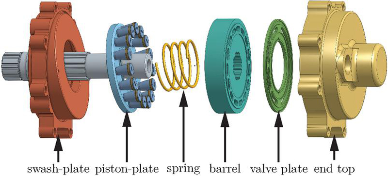
Figure 1 Exploded view of a floating piston machine [3].
However, at low speeds, the hydrodynamic effects diminish drastically, which leaves the cylinder block under-supported, causing solid-body contact and damage [4]. Moreover, this damage further reduces the lubricating interface’s ability to generate hydrodynamic forces and increases leakage, compromising the machine’s performance. To address this issue, Achten et al. introduced a novel hydrostatic bearing within the cylinder block sealing land [4] as shown in Figure 2. Experimental validation by Achten et al. demonstrated the ability of this design to provide hydrostatic support to the cylinder block, particularly at extremely low speeds when hydrodynamic forces are insufficient, while also improving efficiency [2].
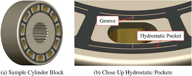
Figure 2 Cylinder block with hydrostatic pockets [3].
This study uses numerical simulations to explore the working principles and evaluate the effectiveness of hydrostatic pockets between the cylinder block and valve plate in a Floating Piston pump. The focus is on comparing contact severity, losses, and gap height distribution under low-speed high-pressure and high-speed high-pressure conditions; additionally, the study evaluates performance at other operating points, including low-speed low-pressure, high-speed low-pressure, and medium-speed medium-pressure conditions. Baseline performance across these operating conditions is compared with variations in hydrostatic pocket configuration, groove size connecting the hydrostatic pockets to the displacement chambers, and hydrostatic pocket size. While the study is performed using a Floating Piston pump platform, the findings are applicable to all piston-type hydraulic machines. The findings seek to provide a deeper understanding of the potential of hydrostatic pockets, contributing to the optimization of piston-type positive displacement machines for a wider range of operating conditions. In this paper, the words hydrostatic pocket and pocket are used interchangeably.
2 Related Literature
This section summarizes literature on lubrication gaps, on Floating Piston pump working principles and on the design of the cylinder-block/valve-plate lubricating interface.
2.1 Lubrication Interfaces in Swash-Plate Type Axial Piston Machines
Conventional axial piston machines possess three main lubrication interfaces: the slipper/swash-plate, the cylinder/piston, and the cylinder block/valve-plate interfaces. Each of these interfaces needs to be carefully balanced to provide a lubrication film that is large enough to reduce friction and avoid wear, but small enough to avoid excessive leakage. The lubrication gaps strongly affect the machine’s lifetime and efficiency, and depending on the operating condition, different hydrostatic and hydrodynamic forces occur in each lubrication gap [7, 8]. Different surface modifications have been suggested for the interface slipper/swash-plate [9, 10] as well as for the interface piston/cylinder [11], showing significant potential for improved lubrication and reduced losses in these interfaces. These two interfaces are not present in floating piston machines as described in Section 2.2 and are partially replaced by an additional piston–plate/swash–plate interface; while this interface is important for the overall lubrication behavior of floating piston machines, its influence on the global cylinder block dynamics is assumed to be secondary and is therefore not explicitly considered in the present study. The third interface, between cylinder block and valve plate, is present in conventional swash-plate machines, as well as in floating cup and floating piston machines. This interface is the main focus of this paper, and background on it is given in Section 2.3.
2.2 Floating Piston Pump Design
The design of a Floating Piston pump is based on the swashplate-type axial piston pump, where the cylinder block, valve plate, and port block are positioned perpendicular to the drive shaft; however, it incorporates several key design differences. As shown in Figure 1, the Floating Piston pump eliminates slippers, fixing the pistons directly onto an inclined plate, known as the piston plate. Ericson and Forssell have explained the working principles and benefits of this novel piston machine [3].
With the piston heads and sealing rings fixed perpendicularly to the piston plate, displacement chamber pressure forces are directly transferred to the pistons and balanced by the piston-plate/swash-plate lubricating interface. This design prevents side forces on the cylinder block. However, the tilted pistons create a wedged volume in the cylinder bore shown in Figure 3(a), with a 3D image shown in Figure 4. The pressurized fluid creates a force imbalance within the displacement chamber, generating a radial force that acts perpendicular to the cylinder bore and on the cylinder block as shown in Figure 3(b). With a properly positioned cylinder-block/shaft reaction point, the moment generated by this radial force on the cylinder block remains symmetric throughout a revolution and can be balanced [3].
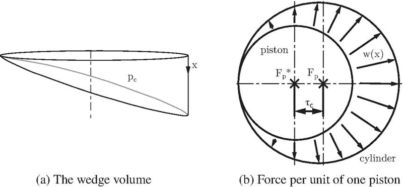
Figure 3 The torque-creating volume in floating piston machines [3].
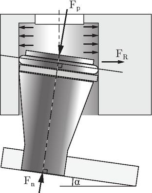
Figure 4 The radial force [3].
Moreover, in traditional axial piston machines, the mass of the piston-slipper assembly, as well as the fluid volume, generates centrifugal forces that must be balanced by the cylinder block. These forces create a tipping moment on the cylinder block. Since these forces are proportional to the square of the shaft speed, traditional machines are highly sensitive to rotational speed, creating a barrier to achieving higher operating speeds. In contrast, the Floating Piston pump connects the pistons on a piston plate, balancing their centrifugal forces and eliminating centrifugal forces transmitted from the piston plate to the cylinder block. Additionally, due to the small dead volume and low piston strokes, the centrifugal forces and moments generated by the fluid volume are also minimized [3]. As a result, this optimized design is expected to enable much higher rotational speeds without requiring an overpowering hold-down central spring, which could otherwise cause additional power losses.
2.3 Block Sealing Land Design
The cylinder-block/valve-plate lubricating interface is one of the most critical design aspects of piston-type positive displacement machines. This interface bears the responsibility of fluid commutation, providing pressure forces to lift the cylinder block away from the valve plate, sealing high-pressure fluid to prevent leakage into the casing, and balancing moments acting on the cylinder block. These functions are achieved through the thrust effect of rapid gap height changes and the wedge effect resulting from converging and diverging surfaces in the circumferential direction. The gap height of the cylinder-block/valve-plate lubricating interface is determined by various factors, including moment and force balances, which are coupled with solid-body deformation. Ultimately, the gap height influences the elasto-hydrodynamic effects, which directly impact power losses in this interface through viscous dissipation, volumetric losses, and solid-body contact friction.
2.3.1 Hydrostatic compensation ratio
Traditionally, an analytical starting point of the block sealing land design is based on the compensation ratio , which compares the loading forces and the compensating hydrostatic forces , see Equation (1) and Figure 5.
| (1) |
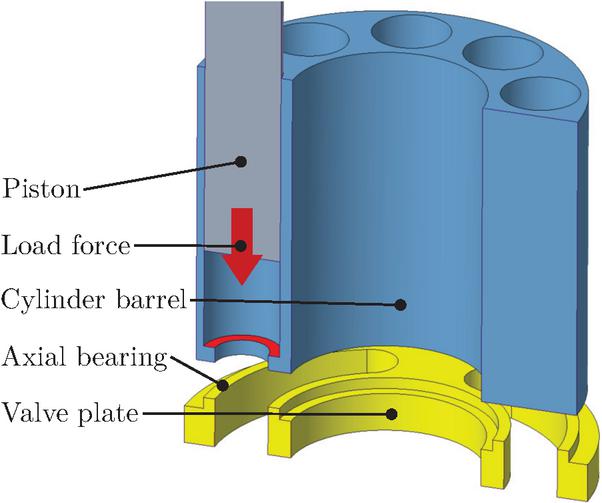
Figure 5 Force and axial bearing between valve plate and block [12].
The compensation ratio only considers hydrostatic forces. The load originates from the pressurized chambers pushing the cylinder block against the valve plate, and the compensation force is defined by the area of the hydrostatic bearing [1].
Compensation ratios above 100% lift the cylinder block off the valve plate, thus causing undesired leakage from the high-pressure port. Thus, compensation ratios need to be smaller than 100%. On the other hand, solid contact between the valve plate and cylinder barrel causes wear. The combination of the two requirements leads to compensation ratios just below 100% [12, 1, 13]. However, note that there are different calculation methods for the compensation ratio [12], and Ernst and Vacca [5] claimed that the hydrodynamic forces in pumps are drastically underestimated, with Vacca and Franzoni [14] stating that typical hydrodynamic forces are in the range of 10 to 20% of the load forces.
2.3.2 Hydrodynamic effects
In a traditional cylinder-block/valve-plate sealing land design, the fluid forces in the lubricating interface depend not only on the pressure from the inlet, outlet ports as well as the casing, but also, more importantly, on the elasto-hydrodynamic wedge and squeeze effects between the valve plate and cylinder block surfaces [5, 15]. However, generating pressure from the wedge effect requires sufficient relative sliding velocity between the two opposing surfaces; consequently, at low speeds, the cylinder-block/valve-plate lubricating interface loses its ability to create effective hydrodynamic wedge pressure, often resulting in metal-to-metal contact.
2.3.3 Waved valve plates
Baker and Ivantysynova [16, 17] simulated waved valve plate designs, and Reddy et al. [18] extended this study. Reddy et al. simulated different wave profiles on a flat valve plate, and tested one of them. The base height of the inner sealing land was higher than the one of the outer sealing land to counteract thermal deformation. Test results showed efficiency improvements for low displacement settings and low speeds, and for the remaining operating conditions the efficiency was similar to the original spherical valve plate.
2.3.4 Design with hydrostatic pockets
In 2010, Innas introduced a new feature within the lubricating interface, incorporating additional chambers in the sealing land, called hydrostatic pockets, along with grooves that connect these pockets to the displacement chamber [19].
The pressure in these hydrostatic pockets is determined by multiple flow paths. First, the groove between the displacement chamber and the hydrostatic pockets acts as a constant orifice. As the displacement chamber pressurizes, hydraulic oil flows into the pocket and pressurizes it. Simultaneously, the sealing lands between the pocket and the displacement chamber as well as between the pocket and the casing act as variable orifices. These variable orifices are passively controlled by the lubricating film gap height distribution [2] as shown in Figure 6.
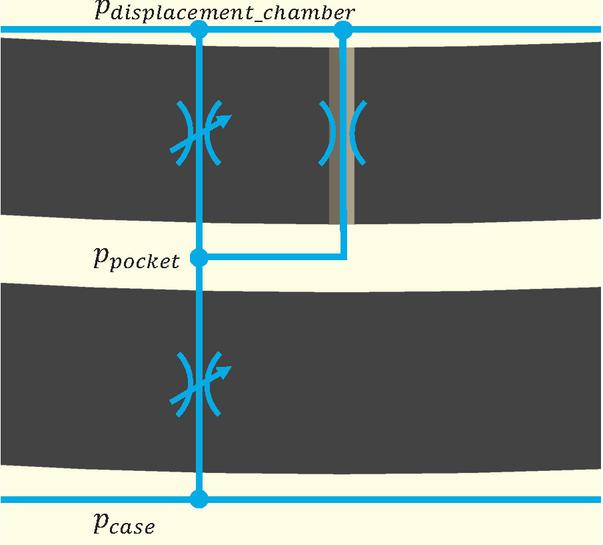
Figure 6 Hydraulic circuit of hydrostatic pocket.
This design provides several benefits, as suggested by Achten et al. [2]. First, the hydrostatic pockets provide additional pressure forces to support the cylinder block to prevent contact with the valve plate even at extremely low shaft speeds, which leads to the diminishing of contact power losses and surface damage. Additionally, the hydrostatic pockets can dynamically balance the cylinder block; when the cylinder block is tilted, the local gap height becomes extremely small, causing the variable orifices’ areas connecting the pockets in the outer edge of the sealing land and the casing to reduce to nearly zero. This effectively cuts off the outlet flow from the outer pockets, and since the constant orifices connecting the pockets and the displacement chambers are independent of the gap height, the inlet flow to the pockets allows the pocket pressure to reach a level similar to that of the displacement chamber, which provides additional force to counteract the cylinder block’s moment imbalance. Conversely, when less force is needed, a higher gap height increases the variable orifices’ area, balancing the inlet and outlet flow to the pocket and reducing the hydrostatic pressure.
3 Modeling Approach
The modeling approach for simulating the cylinder-block/valve-plate lubricating interface is developed using a multi-physics simulation suite, Multics [20]. Although Multics is capable of simulating all three lubricating interfaces in a piston machine, as well as the dynamic coupling between each module, this study is limited to the cylinder-block/valve-plate interface, and the information flow is illustrated in Figure 7 [15].
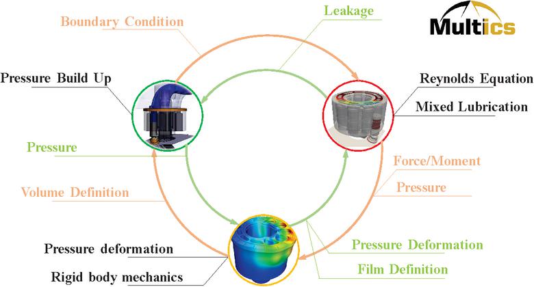
Figure 7 Modeling information flow.
3.1 Lumped Parameter Model
The pressure within the displacement chambers is simulated using Hopsan [21], which employs a lumped parameter model as shown in Figure 8. The model computes the translational movements of the pistons and solves the continuity equation for each chamber. Pseudo-cavitation and the pressure dependency of the bulk modulus are considered. The openings of the chambers to each port are modeled as variable orifices. The model assumes no leakage and friction. The lumped parameter model is used to compute the pressure profile under consideration of commutation effects for each operating point. Multics then reads in the pressure profile in the displacement chambers as a look-up table based on the shaft rotation angle.
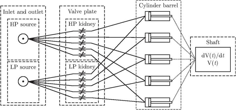
Figure 8 Lumped parameter model structure [22].
The pressure from the displacement chambers, used as the upstream pressure for the hydrostatic pockets, always connects to the pockets through constant-area orifices. The grooves feature an isosceles triangular cross-section, where the width equals twice the height. The width of these orifices is initially chosen to be 75 m, which is smaller than the lowest width of 124 m tested by Achten et al. [2] and determined for optimal power efficiency. In Section 4.3, the orifice widths are then varied from 0 m to 200 m, and Section 4.3.6 investigates the interaction of groove size and pocket position. The mass flow rate through the orifices into a given hydrostatic pocket, , is calculated using the orifice equation shown in Equation (2).
| (2) |
The hydrostatic pockets are modeled as fluid volumes, and the pressure is calculated using the isothermal pressure build-up equation, as shown in Equation (3). Since there is no volume derivative for the hydrostatic pockets, the last term can be omitted.
| (3) |
The pressures from the inlet ports, outlet ports, casing, displacement chambers, and hydrostatic pockets serve as pressure boundaries for the lubricating interface model. These pressures are also used to apply loads to the cylinder block.
3.2 Lubricating Film Model
There are three lubricating interfaces in a Floating Piston machine. However, since the focus of this study is on the effect of hydrostatic pockets on the cylinder block, and the majority of forces from the piston and piston plate do not transfer to the cylinder block, only the cylinder-block/valve-plate lubricating interface is simulated.
The traditional form of the Reynolds equation is written in terms of the pressure, as shown by Hamrock et al. [23]. However, this formulation is unable to simulate the cavitated regions in the lubricating interface precisely, leading to an incorrect flow estimation. Therefore, Ransegnola proposed the density-based Reynolds equation accounting for cavitation effects and providing accurate flow predictions[20]. In addition, Ransegnola utilized statistical mixed lubrication relations to formulate the universal mixed Reynolds equation, as shown in Equation (4), which is used in Multics [24, 25, 26].
| (4) | ||
The Reynolds equation shows that Poiseuille flow equals the sum of Couette flow, flow dragged by asperities, and local expansion. It provides the pressure distribution within the lubricating interface, which governs leakage – the net volumetric flow across the boundaries of the film. Leakage consists primarily of pressure-driven Poiseuille flow, but it is also enhanced by local surface motion and asperity effects (Couette contributions). The cylinder block gap heights and outlet pressure dictate the leakage rate: larger gap heights and higher inlet pressures produce stronger Poiseuille flows, whereas lower pressures reduce leakage. Accurate prediction of volumetric leakage is essential for this study, since the equivalent variable orifices that connect the hydrostatic pockets to the displacement chamber and casing are directly determined by the local film flow.
In addition to leakage, the pump’s losses can also be captured from torque loss or viscous shear stress, which arises from the shear forces resisting the relative motion of the cylinder block and valve plate. This loss includes Couette shear due to sliding surfaces, Poiseuille shear driven by pressure gradients, and solid contact friction when asperities interact under small gap heights.
Both leakage and torque losses manifest through viscous dissipation. The power dissipated in the film represents the conversion of mechanical energy into heat due to fluid shear. This dissipation includes contributions from viscous shear stresses and the high-pressure fluid leakage itself [27]. The governing expression used in Multics is given by Equations (5)–(6), where denotes the local dissipation function in polar coordinates. It is worth noting that viscous dissipation considers the fluid film only, and the energy dissipation due to frictional contact is calculated separately. However contact dissipation is not within the scope of this paper, since solid body contact is to be avoided.
| (5) | |
| (6) |
In summary, leakage quantifies flow losses, torque quantifies force losses, and viscous dissipation represents the total energy loss, unifying both mechanisms. At low pressure and high speed, Couette shear dominates the film behavior, so viscous dissipation is closely correlated with torque loss. At higher pressures and lower speeds, Poiseuille shear becomes dominant, making viscous dissipation more closely aligned with leakage.
Finally, the pressure distribution is used for body dynamics calculations as well as solid-body deformation analysis to estimate the accurate gap height in the lubricating interface.
3.3 Body Dynamics Model
The axial forces and moments arising from the pressurized fluid in the displacement chamber and the lubricating interface are used to solve the equations of conservation of linear and angular momentum for the cylinder block body, as shown in Equation (7) and Equation (8); encompassing three degrees of freedom, allowing the cylinder block to move in the axial direction and tilt around the cylinder-block/shaft reaction point, or the crowing point, which also balances the block’s radial forces and provides the drive torque to rotate the cylinder block [13].
| (7) | |
| (8) |
The radial forces and moments from the wedge-shaped fluid inside the displacement chamber shown in Figure 4, caused by the tilted piston and piston sealing ring, are calculated using Equations (9) and (10) [3].
| (9) | |
| (10) |
Moreover, to accurately evaluate contact severity and power loss within the lubricating interfaces, it is essential to account for solid-body deformation [6]. In this simulation model, the half-space method based on the Hertzian contact stress is employed to evaluate the deformation in the cylinder block and valve plate caused by local fluid film pressure and contact pressure.
Contact friction at the cylinder block–valve plate interface is included with a constant friction coefficient in the present model, and it plays an important role in the dynamic behavior of the floating cylinder block. When local film thickness decreases, and mixed-lubrication conditions and penetration occur, frictional forces introduce additional tangential loads and moments acting on the cylinder block. These forces can alter the block’s tilting behavior, transient stability, and dynamic equilibrium position.
Finally, the resulting cylinder block positions, velocities, and deformation are fed back to assess the influence of squeeze and wedge phenomena on the lubricating interface through the Reynolds equation.
4 Results and Discussion
4.1 Simulation Setup
4.1.1 Hydrostatic pocket configurations
Four groups of operating conditions are tested, as outlined in Table 1: Low-Speed High-Pressure (LSHP), High-Speed Low-Pressure (HSLP), High-Speed High-Pressure (HSHP), and Medium-Speed Medium-Pressure (MSMP). These conditions are defined by the rotational speed and outlet pressure, where low-speed is 300 rpm, medium-speed is 2000 rpm, and high-speed is 6000 rpm, while low-pressure is 20 bar, medium-pressure is 200 bar, and high-pressure is 350 bar.
To evaluate the effectiveness of the hydrostatic pockets, a baseline pump without pockets is simulated alongside configurations where pockets are positioned on the inside (Inner Pockets), outside (Outer Pockets), or both sides (Both Pockets) of the sealing land. Each configuration is further analyzed based on the pocket placement relative to the displacement chamber: one set positioned closer to the chamber (Small Area) and the other set positioned farther away (Large Area), representing the different areas of the sealing land trapped between the pockets and the displacement chambers, as illustrated in Figure 9.
Table 1 Simulated hydrostatic pocket designs and operating conditions
| Operating Condition | Baseline | Small Area Inner Pockets | Small Area Outer Pockets | Small Area Both Pockets | Large Area Inner Pockets | Large Area Outer Pockets | Large Area Both Pockets |
| Low-speed High-pressure | ✓ | ✓ | ✓ | ✓ | ✓ | ✓ | ✓ |
| High-speed Low-pressure | ✓ | ✓ | ✓ | ✓ | ✓ | ✓ | ✓ |
| High-speed High-pressure | ✓ | ✓ | ✓ | ✓ | ✓ | ✓ | ✓ |
| Medium-speed Medium-pressure | ✓ | ✓ | ✓ | ✓ | ✓ | ✓ | ✓ |
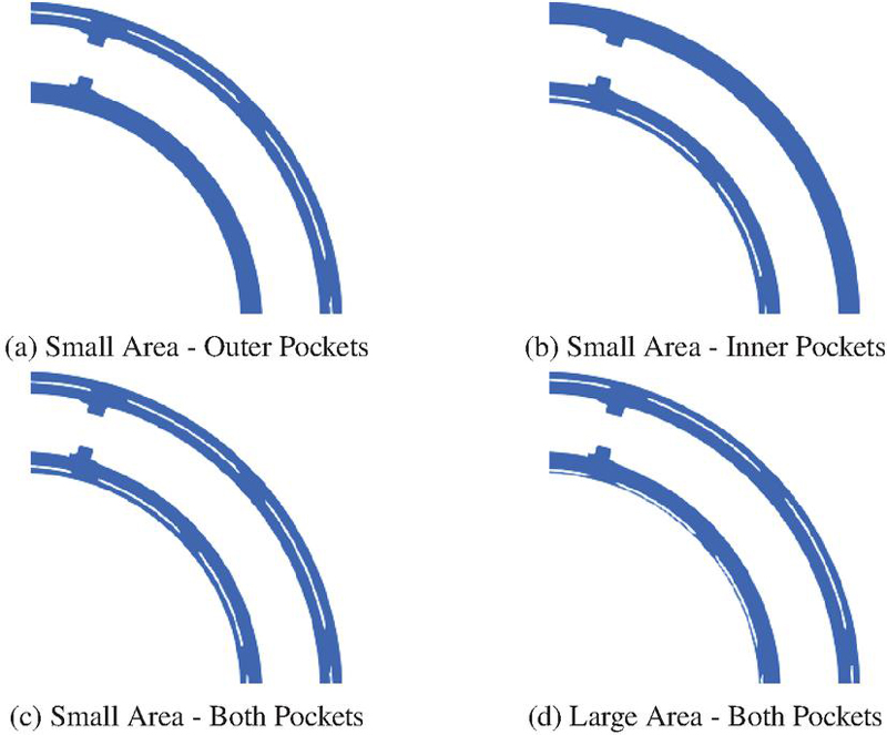
Figure 9 Hydrostatic pockets location examples.
To create a fair comparison between the outer and inner pockets, the locations are determined by maintaining the lubricating interface area between the hydrostatic pockets and the displacement chambers. This assumption is based on the premise that the additional hydrostatic pressure in the lubricating film generated by the pockets is directly proportional to this area. Lastly, to accurately evaluate the efficacy of the hydrostatic pockets as well as the differences between different configurations, local meshing surrounding the pockets in the lubricating film model is refined.
4.1.2 Groove size configurations
Furthermore, to study the effect of the grooves that act as constant area orifices connecting the hydrostatic pockets and displacement chambers, their sizes are studied from 0 micrometers to 200 micrometers as outlined in Table 2. For this study, the Low-speed low-pressure (LSLP) operating condition is added; for all operating conditions, three hydrostatic pocket configurations are simulated: Baseline, Large Area – Inner Pockets, Large Area – Both Pockets.
Table 2 Simulated groove sizes and operating conditions
| Operating Condition | 0 m | 25 m | 50 m | 75 m | 100 m | 125 m | 150 m | 200 m |
| Low-speed High-pressure | ✓ | ✓ | ✓ | ✓ | ✓ | ✓ | ✓ | ✓ |
| Low-speed Low-pressure | ✓ | ✓ | ✓ | ✓ | ✓ | ✓ | ✓ | ✓ |
| High-speed Low-pressure | ✓ | ✓ | ✓ | ✓ | ✓ | ✓ | ✓ | ✓ |
| High-speed High-pressure | ✓ | ✓ | ✓ | ✓ | ✓ | ✓ | ✓ | ✓ |
| Medium-speed Medium-pressure | ✓ | ✓ | ✓ | ✓ | ✓ | ✓ | ✓ | ✓ |
Additionally, for the Low-speed high-pressure (LSHP) operating condition, the groove size is studied for the Small Area – Inner Pockets and Small Area – Both Pockets configuration in order to evaluate the relationship between pocket position and ideal groove size.
4.1.3 Hydrostatic pocket width configurations
Lastly, the impact of the size of the hydrostatic pockets is studied by maintaining the same angular span and varying their widths and depths for the Low-speed High-pressure case, for Baseline, Large Area – Inner Pockets, and Large Area – Both Pockets configurations, as shown in Table 3.
Table 3 Simulated pocket widths and depths (low-speed, high-pressure)
| Pocket Width | 0.133 mm | 0.267 mm | 0.400 mm |
| Pocket Depths | 0.03 mm | 0.3 mm | 3 mm |
4.1.4 Artificial moment sensitivity study
To ensure the applicability of this study, a sensitivity analysis is performed under the medium-speed medium-pressure operating condition to determine the crowning point location for the remaining simulations. As introduced in the modeling approach Section 3.3, the crowning point directly influences the moments applied to the cylinder block, impacting its stability and overall performance. As shown in Figure 10, the viscous power loss and the moments acting on the cylinder block are normalized for ease of comparison.
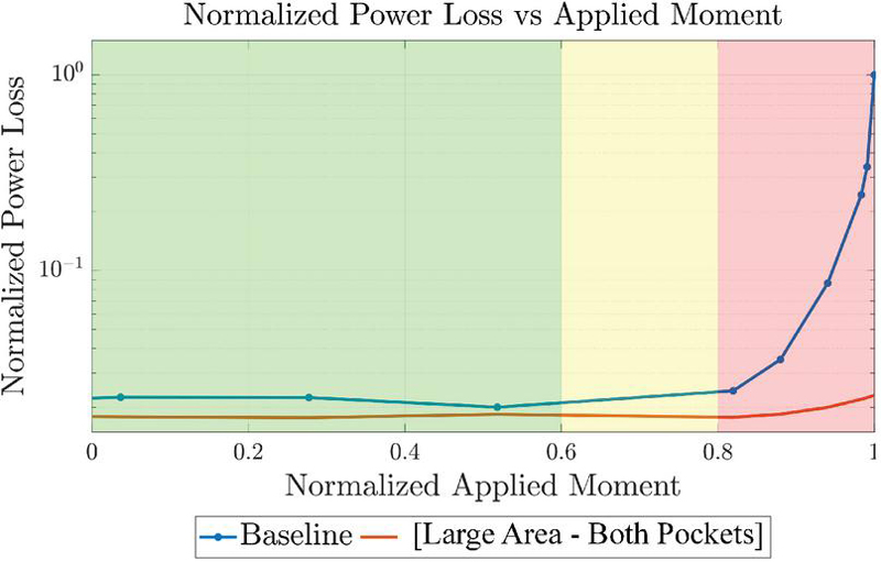
Figure 10 Normalized power loss vs. applied moment.
The green zone in the sensitivity analysis represents the optimal scenario, indicating that solid-body deformation, manufacturing tolerances, wear, and other factors are functioning without causing a large shift at the moments applied to the cylinder block. Meanwhile, the orange zone shows the scenarios where small disturbances may introduce some deviations, such as manufacturing imperfections and wear, but are still within acceptable limits. Finally, the red zone represents the extreme conditions where the cylinder block experiences significant moment imbalance, resulting in instability and further decreased performance. It can be seen that as the moment applied to the cylinder block increases, the viscous power loss for the baseline machine increases exponentially; meanwhile, with the addition of the hydrostatic pockets, the power losses are kept at a constant low level.
For this study, simulations are conducted assuming the worst-case scenario for several reasons. First, testing the hydrostatic pockets under such conditions ensures this feature will remain effective even in the most non-optimal situations. Second, since the piston-seal/cylinder-bore friction forces and oil inertia forces are not included in these simulations, assuming a non-ideal crowning point would help to increase the robustness of this study. Lastly, while the baseline cylinder block in a Floating Piston pump exhibits mostly balanced moments, the study is made more general when the crowning point is placed sub-optimally due to the complexities of a typical axial piston unit, providing more reliable insights that can be applied to a wider range of applications.
4.2 Effect of Hydrostatic Pocket Configuration on Block Performance
This section presents results under different operating conditions to compare and contrast the benefits of using hydrostatic pockets and their optimal configurations.
4.2.1 Low-speed high-pressure
As discussed in Section 2.3.2, low-speed operating conditions are a major challenge for the cylinder-block/valve-plate lubricating interface in a piston machine due to the lack of the hydrodynamic wedge effect. Furthermore, the high outlet pressure presents a greater moment imbalance for the cylinder block caused by radial chamber forces. Thus, at this operating condition, the benefits from the addition of hydrostatic pockets become more pronounced. The lowest simulated speed performed is 100 rpm, and the results show similar behavior to the 300 rpm case discussed in this section; however, due to the nature of the simulation, decreasing the shaft speed significantly increases wall time.
The maximum and the minimum gap heights of the cylinder-block/valve-plate lubricating interface are shown in Figure 11 over one displacement chamber period, which is 360 degrees divided by the number of pistons. The baseline case results show that the maximum gap height is close to 90 micrometers, while the minimum gap height is below 0.2 micrometers, indicating that the block is severely tilted. With the addition of hydrostatic pockets, not only does the minimum gap height increase and the maximum gap height decrease, but the cylinder block also exhibits a much lower amplitude of tilting oscillation, indicating that the unbalancing motion is significantly reduced.
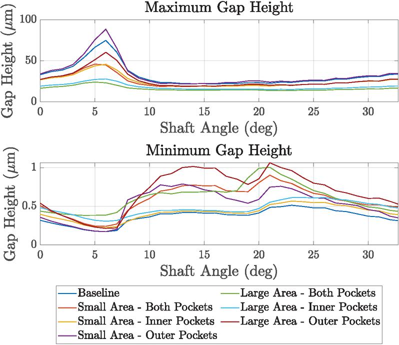
Figure 11 LSHP – gap heights, ,
[Groove Width 75 m, Pocket Width 0.4 mm, Pocket Depth 0.3 mm].
The relief of strong tilting motion is also reflected in the metal-to-metal contact behavior. As shown in Figure 12, the baseline case experiences the highest magnitude of contact pressure, indicating that the lubricating film is unable to balance the moment. It is worth noting that in both the Large Area – Inner Pockets and Large Area – Both Pockets cases, no solid-body contact is observed.
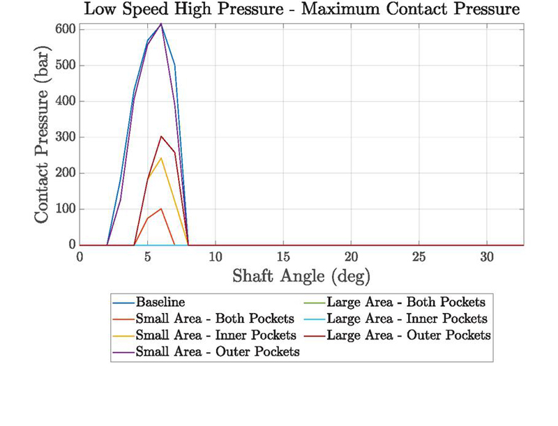
Figure 12 LSHP – maximum contact pressure,
[Groove Width 75 m, Pocket Width 0.4 mm, Pocket Depth 0.3 mm].
The condition in which the hydrostatic pockets are pressurized is an important aspect of this study. Figure 13 demonstrates that, initially, when the local gap height is large, the pressure in the outer pocket is maintained at the average level between the casing and displacement chamber; and as the pocket transitions into the low gap height region, its pressure increases and approaches the level of the displacement chamber. For the inner pockets, also as illustrated in Figure 13, the relatively neutral and stable gap height distribution towards the center of the cylinder block prevents a significant pressure increase. This distinction between inner and outer pockets showcases the dynamic behavior of pressurization in the hydrostatic pockets and their dependency on local film thicknesses.
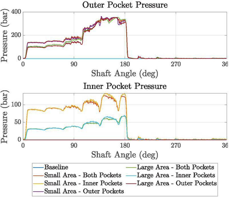
Figure 13 LSHP – pocket pressures, ,
[Groove Width 75 m, Pocket Width 0.4 mm, Pocket Depth 0.3 mm].
This behavior can be further observed through the pressure distribution shown in Figure 14, where the colors represent pressure levels, with red being high pressure and blue being low pressure. The high-pressure delivery ports are located on the left side of the valve plate, and the cylinder block is rotating counterclockwise, as indicated in the figures. During the high-pressure zone, as the displacement chamber rotates from the high gap height region to the low gap height region, the hydrostatic pocket begins to pressurize as its color approaches the color of the displacement chamber. This dynamic behavior demonstrates that hydrostatic pockets adapt their pressure and provide hydrostatic support depending on the gap height, passively mitigating tilting.
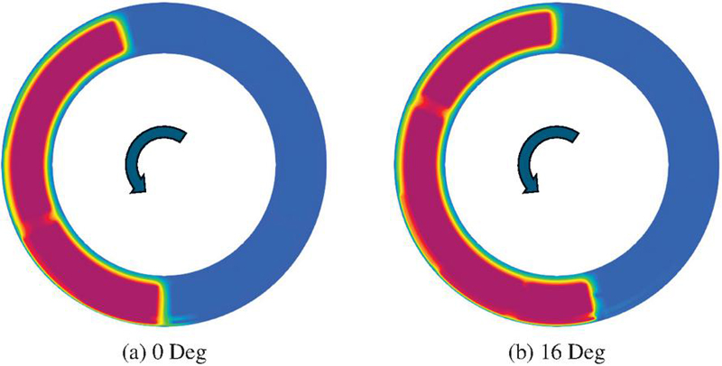
Figure 14 LSHP – large area – both pockets – film pressure
[Groove Width 75 m, Pocket Width 0.4 mm, Pocket Depth 0.3 mm].
Moreover, as shown in Table 4, the viscous power loss from the cylinder-block/valve-plate lubricating interface is reduced with the addition of the hydrostatic pockets, with the greatest reductions being the cases with the Large Area – Inner Pockets and Large Area – Both Pockets configurations. There are two key findings from the results. First, hydrostatic pockets not only generate additional hydrostatic force within their areas but also help elevate the pressure in the surrounding lubricating film, particularly when the gap heights are low, creating an additional boundary for the lubrication fluid between the pockets and displacement chambers. As shown in Figure 15, the pressure in the pockets and the fluid film approach similar levels as the displacement chamber. Therefore, locating the hydrostatic pockets farther away from the displacement chambers further increases the hydrostatic force when necessary, improving cylinder block balance.
Table 4 LSHP – viscous power loss
| Pocket Setup | Power Loss Reduction [%] |
| Baseline | – |
| Small Area – Inner Pockets | 57.1 |
| Small Area – Outer Pockets | 26.6 |
| Small Area – Both Pockets | 53.9 |
| Large Area – Inner Pockets | 82.5 |
| Large Area – Outer Pockets | 41.7 |
| Large Area – Both Pockets | 85.4 |
The second point may seem counterintuitive. Although locating the pockets closer to the outer edge of the cylinder block sealing land generates larger balancing moments, the squeeze effect of the bearing results in high pressure near the outer edge, where gap heights are minimal and oscillating. This generated hydrodynamic pressure diminishes the contribution of the hydrostatic pockets, reducing their effectiveness. In contrast, positioning the pockets on the inner side of the sealing land, while having a shorter moment arm, enhances the pressure in the lubricating interface where all hydrodynamic effects are weak. Therefore, locating the hydrostatic pockets on the inner or both sides of the cylinder block is more effective for mitigating block tilting and solid-body contact.
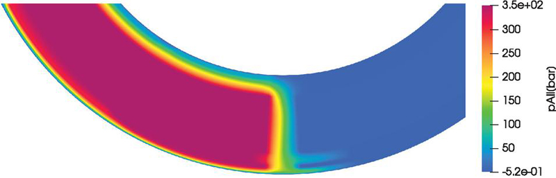
Figure 15 LSHP – large area – both pockets – pressure zoomed at 0 deg
[Groove Width 75 m, Pocket Width 0.4 mm, Pocket Depth 0.3 mm].
4.2.2 High-speed high-pressure
High-speed high-pressure condition also leads to challenges in lubricating the cylinder-block/valve-plate interface. While elevated rotational speeds enhance hydrodynamic wedge effects, helping balance the cylinder block and reduce viscous and contact losses, the simultaneous presence of high pressures increases the risk of moment imbalances, potentially compromising stability.
Simulation results in Figure 16 show that, under HSHP conditions, the baseline configuration exhibits large film thickness variation, causing increased tilting. The introduction of hydrostatic pockets improves the cylinder block stability by providing additional pressure support to counteract these tilting moments. More specifically, Figure 16 illustrates how pocket pressure dynamically adjusts to film height variations in order to maintain more uniform gap height distributions and enhance moment balancing.
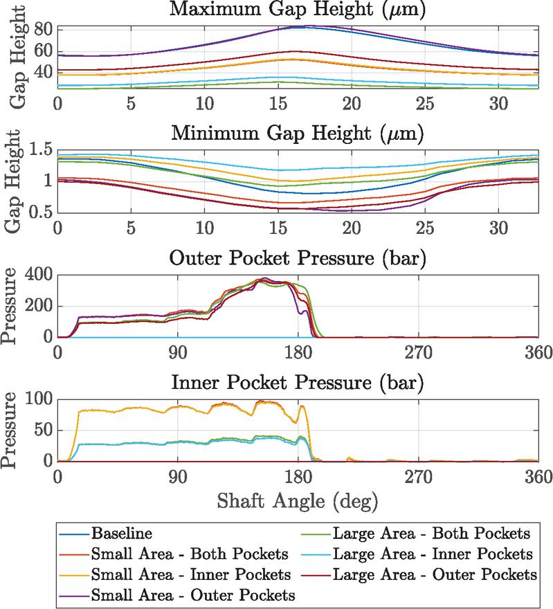
Figure 16 HSHP – gap heights and pocket pressures
[Groove Width 75 m, Pocket Width 0.4 mm, Pocket Depth 0.3 mm].
Table 5 compares viscous power losses across different hydrostatic pocket configurations, consistent with the low-speed high-pressure operating condition, showing that the Large Area – Inner Pockets and Large Area – Both Pockets cases achieve the greatest reductions. These results further emphasize the importance of the hydrostatic pocket placements to maximize performance.
Table 5 HSHP – viscous power loss
| Pocket Setup | Power Loss Reduction [%] |
| Baseline | – |
| Small Area – Inner Pockets | 59.8 |
| Small Area – Outer Pockets | 4.5 |
| Small Area – Both Pockets | 60.9 |
| Large Area – Inner Pockets | 73.3 |
| Large Area – Outer Pockets | 50.7 |
| Large Area – Both Pockets | 76.6 |
4.2.3 High-speed low-pressure
Compared with the LSHP and HSHP operating conditions, the high-speed low-pressure case is inherently more stable due to the strong hydrodynamic edge effects resulted by high relative sliding velocity and low radial chamber forces and moments, as shown in Figure 17.
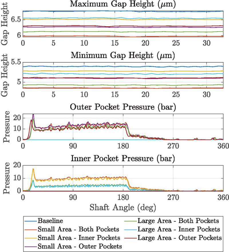
Figure 17 HSLP – gap heights and pocket pressures
[Groove Width 75 m, Pocket Width 0.4 mm, Pocket Depth 0.3 mm].
The pressure within the hydrostatic pockets does not increase significantly as shown in Figure 17, indicating that the hydrostatic pockets are not over-pressurized when there is no motivation to create additional balancing moments on the cylinder block.
Lastly, since there is no excessive moment tilting the cylinder block, the power loss reduction due to the hydrostatic pockets is less significant. However, the slight reduction, as shown in Table 6 suggests that hydrostatic pockets can still provide benefits even when the cylinder block is inherently balanced.
Table 6 HSLP – viscous power loss
| Pocket Setup | Power Loss Reduction [%] |
| Baseline | – |
| Small Area – Inner Pockets | 0.42 |
| Small Area – Outer Pockets | 2.82 |
| Small Area – Both Pockets | 1.92 |
| Large Area – Inner Pockets | 0.01 |
| Large Area – Outer Pockets | 3.44 |
| Large Area – Both Pockets | 3.96 |
4.2.4 Medium-speed medium-pressure
Table 7 presents the power loss reduction with and without the incorporation of hydrostatic pockets, and the results are aligned with the findings under other operating conditions.
Table 7 MSMP – viscous power loss
| Pocket Setup | Power Loss Reduction [%] |
| Baseline | – |
| Small Area – Inner Pockets | 90.7 |
| Small Area – Outer Pockets | 59.1 |
| Small Area – Both Pockets | 90.8 |
| Large Area – Inner Pockets | 95.1 |
| Large Area – Outer Pockets | 90.3 |
| Large Area – Both Pockets | 95.9 |
Unlike some other operating conditions examined, the medium-speed medium-pressure operation conditions do not typically lead to severe failure of the pump, such as strong metal-to-metal contact or excessive gap height variation; however, since hydraulic machines frequently operate under these conditions, the power efficiency is critical.
4.3 Effect of Groove Size on Block Performance
This section presents the simulation results for different groove sizes under five representative operating conditions, considering both the Large Area – Both Pocket and Large Area – Inner Pocket hydrostatic pocket configurations. This is because these two configurations showed the most promising results in Section 4.2. The results reveal consistent trends across operating conditions, while also highlighting important variations that depend on speed and pressure.
4.3.1 Low-speed, high-pressure condition
The maximum and minimum gap heights of the cylinder-block/valve-plate lubricating interface for both the Large Area – Both Pocket and Large Area – Inner Pocket cases are shown in Figures 18 and 19 over one displacement chamber period.
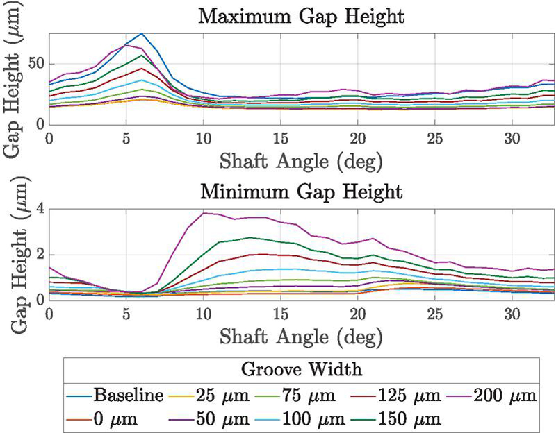
Figure 18 LSHP – large area – both pockets: gap heights (, )
[Pocket Width 0.4 mm, Pocket Depth 0.3 mm].
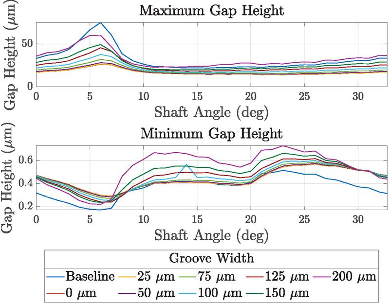
Figure 19 LSHP – large area – inner pocket: gap heights, ,
[Pocket Width 0.4 mm, Pocket Depth 0.3 mm].
As the groove size increases, both the maximum and minimum gap heights increase, approaching the baseline result. This behavior can be explained by the increase in hydrostatic pocket pressure with larger groove sizes, as shown in Figure 20; since the groove functions as a constant-area orifice feeding high-pressure fluid from the displacement chambers. As the cylinder block becomes slightly overbalanced and lifts off from the valve plate, the gap height increases to allow excess flow to exit the pockets through implicit orifices across the lubricating interface, which reduces the severity of cylinder block tilting.
Conversely, as the groove size decreases, the maximum and minimum gap heights also decrease, resulting in a more stable response. The 0 m and 25 m grooves show nearly identical behavior. This similarity arises because, at small groove sizes, the flow into the pocket becomes dominated by film leakage rather than the orifice. Consequently, the no-groove case produces a comparable inflow and outflow balance to that of a very small groove. Compared to the baseline without hydrostatic pockets, where the block relies solely on hydrodynamic effects and the diffuse pressure gradient from the high-pressure ports, even the 0 m no-groove case outperforms it by providing localized hydrostatic support that elevates pressure between the pocket and displacement chamber, supplying additional compensation.
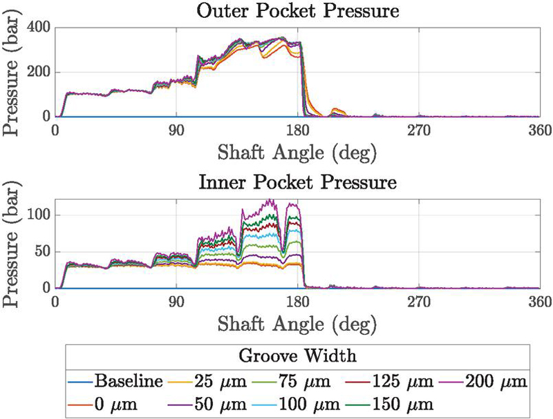
Figure 20 LSHP – large area – both pocket: pocket pressures, ,
[Pocket Width 0.4 mm, Pocket Depth 0.3 mm].
For the Large Area–Inner Pocket case, increasing the groove size causes the cylinder block to come into contact with the valve plate due to increased block tilting, see Figure 21. However, compared to the baseline design, both the peak contact pressure and the angular contact span are significantly reduced.
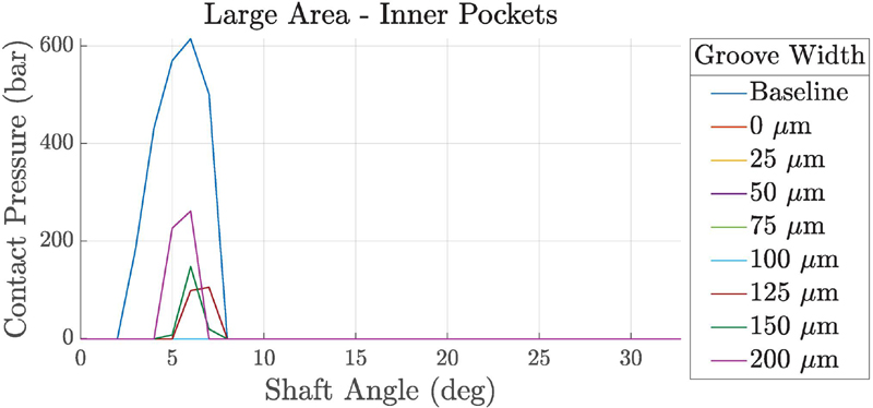
Figure 21 LSHP – large area – inner pocket: max contact pressure,
[Pocket Width 0.4 mm, Pocket Depth 0.3 mm].
For the Large Area–Both Pocket case, the no-groove configuration shows brief contact between the cylinder block and the valve plate, see Figure 22. This is due to lower hydrostatic compensation pressure, which leads to a smaller gap height, although the block remains more level than in the baseline case.
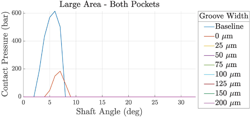
Figure 22 LSHP – large area – both pocket: max contact pressure,
[Pocket Width 0.4 mm, Pocket Depth 0.3 mm].
Figure 23 illustrates the variation of block film viscous dissipation, leakage, drive torque, and shear moment with increasing groove size, normalized by the baseline performance at the current operating condition. At low speed and high pressure, leakage is primarily driven by Poiseuille flow. As shown in Figure 23, leakage rises sharply with increasing groove size, while the 0 m and 25 m grooves again show nearly identical behavior. This occurs because the cylinder block remains at a low gap height for both pocket configurations, reducing available leakage paths. At larger groove sizes, more inflow occurs in the hydrostatic pockets, strengthening the hydrostatic support locally, but it is unbalanced globally, which increases block tilting, leading to higher leakage and energy loss.
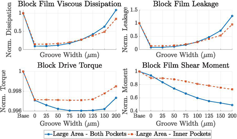
Figure 23 LSHP – large area: normalized loss components
[Pocket Width 0.4 mm, Pocket Depth 0.3 mm].
Torque losses are higher at smaller groove sizes due to reduced gap heights and higher shear rates. These losses decrease as the groove size (and gap height) increases, but rise again when the block begins to tilt and wobble excessively. For both pocket configurations, torque losses are lower than in the baseline case, since the baseline experienced strong solid contact between the cylinder block and valve plate. It is worth noting that in the simulations, the block drive torque is evaluated in the fixed Earth frame, while the film shear moment is calculated in the body frame moving with the block. Increased block tilting can therefore cause slight misalignment between the two curves.
Lastly, viscous dissipation is strongly influenced by Poiseuille shear under high pressure, aligning more closely with leakage than with torque. Overall, the Large Area–Both Pocket configuration provides better performance in terms of torque loss due to stronger hydrostatic compensation, while the Large Area–Inner Pocket configuration better mitigates leakage, resulting in lower viscous dissipation.
4.3.2 Low-speed, low-pressure condition
At low speed and pressure, pressure gradients across the lubricating interface are weak due to limited hydrostatic and hydrodynamic effects, so leakage remains small for all groove widths. Nevertheless, leakage increases with groove width for both the Large Area–Both Pocket and Large Area–Inner Pocket configurations. At larger groove widths, both the maximum gap height and leakage rise substantially, providing excess hydrostatic support while reducing the stabilizing effect and causing the cylinder block to tilt as shown in Figures 24 and 25
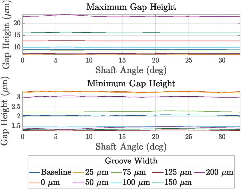
Figure 24 LSLP – large area – both pocket: gap heights, ,
[Pocket Width 0.4 mm, Pocket Depth 0.3 mm].
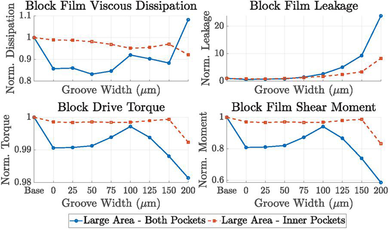
Figure 25 LSLP – large area: normalized loss components
[Pocket Width 0.4 mm, Pocket Depth 0.3 mm].
Torque loss is consistently lower than in the baseline case, since the cylinder block remains lifted from the valve plate. Smaller grooves sustain relatively higher torque losses due to weaker pressure support, while larger grooves reduce torque-related shear losses but at the expense of stability. Viscous dissipation is shared between Poiseuille and Couette shear under these conditions, as neither contribution dominates. Between the two pocket configurations, the Large Area–Both Pocket case generally exhibits lower dissipation than the Large Area–Inner Pocket case due to its larger effective pocket area, although this advantage diminishes at large groove sizes where excessive leakage offsets the benefit.
4.3.3 High-speed, high-pressure condition
At high speed and high pressure, leakage becomes significant due to strong pressure gradients and high Couette shear contributions. As the groove size increases, the cylinder block experiences higher hydrostatic support, and the gap height rises, resulting in stronger leakage flow. Consequently, the resisting moment generated by the fluid film decreases with increasing gap height, and the torque loss steadily decreases with groove width.
It is difficult to determine whether Poiseuille or Couette shear dominates the viscous dissipation under this condition; however, as shown in Figure 26, the results indicate that viscous dissipation closely follows the leakage trend. Both pocket configurations exhibit similar overall viscous power loss. At smaller groove sizes, the Large Area–Both Pocket case shows lower leakage but higher torque loss, while at larger groove sizes the opposite trend is observed.
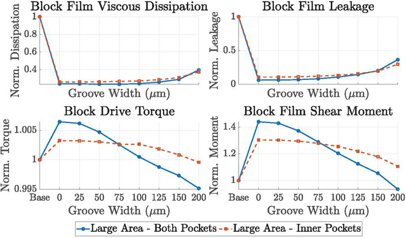
Figure 26 HSHP – large area: normalized loss components
[Pocket Width 0.4 mm, Pocket Depth 0.3 mm].
4.3.4 High-speed, low-pressure condition
At high speed and low pressure, as shown in Figure 27, viscous dissipation correlates most strongly with torque, since the pressure gradient is weak and sliding shear dominates the energy losses through Couette flow. Leakage increases with groove width, particularly beyond 100 m. Larger grooves reduce torque and dissipation but compromise stability by producing higher gap heights, whereas torque losses remain substantial in the 0–100 m cases due to sustained hydrodynamic loading associated with lower hydrostatic compensation and reduced gap heights.
The Large Area–Inner Pocket configuration consistently exhibits higher dissipation than the Large Area–Both Pocket case, owing to its smaller pocket-influenced area and the resulting shallower reduction in torque loss. The similarity between the small-groove cases confirms that the lubricating film edge alone is sufficient to regulate flow and maintain stabilization, even without a machined groove.
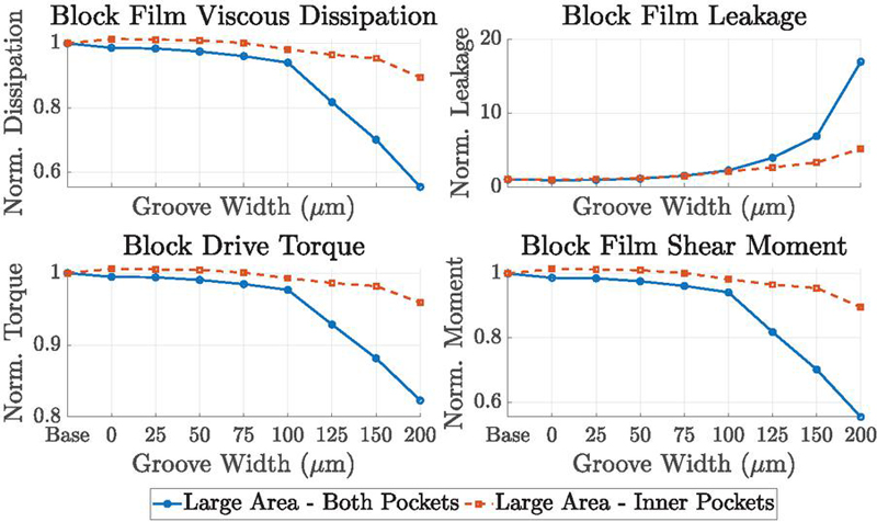
Figure 27 HSLP – large area: normalized loss components
[Pocket Width 0.4 mm, Pocket Depth 0.3 mm].
4.3.5 Medium-speed, medium-pressure condition
Under intermediate operating conditions, the behavior is very similar to the high-speed, high-pressure case: leakage flow increases with groove size, while torque loss decreases. Both hydrostatic pocket configurations exhibit comparable overall viscous power loss.
As with the high-pressure case, it is difficult to determine a priori whether Poiseuille or Couette shear dominates the viscous dissipation. However, as shown in Figure 28, the results indicate that viscous dissipation closely follows the leakage trend.
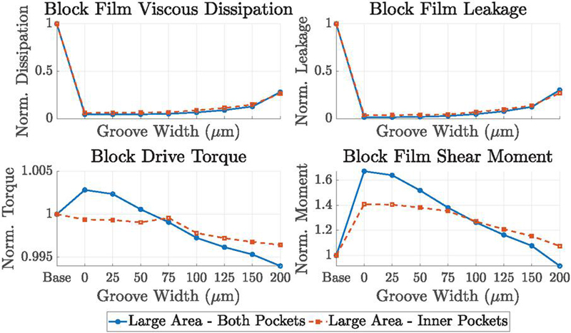
Figure 28 MSMP – large area: normalized loss components
[Pocket Width 0.4 mm, Pocket Depth 0.3 mm].
4.3.6 Dependency of ideal groove size on pocket position
After investigating the pocket configuration and groove size, it is also important to examine whether the block’s performance depends on an ideal pairing of groove size and pocket position. Thus, the Small Area – Both Pockets and Small Area – Inner Pockets configurations are also simulated for the low-speed, high-pressure operating condition. As concluded in Section 4.2, these two pocket configurations do not perform as well as the similar Large Area cases. The same conclusion can be drawn here: for any given groove width, the Small Area cases exhibit more tilting and higher contact pressure, as shown in Figures 29 and 30, compared to the results shown in Figures 22 and 29.
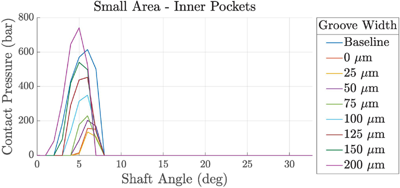
Figure 29 LSHP – small area – inner pocket: max contact pressure,
[Pocket Width 0.4 mm, Pocket Depth 0.3 mm].
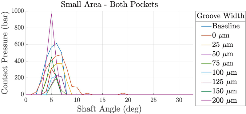
Figure 30 LSHP – small area – both pocket: max contact pressure,
[Pocket Width 0.4 mm, Pocket Depth 0.3 mm].
Furthermore, due to the cylinder block tilting and solid-body contact, the Small Area cases show higher leakage, torque loss, and viscous dissipation (Figure 31) than the Large Area results shown in Figure 23. However, if a smaller groove (75 m width) is paired with the Small Area cases, the losses can be lower than those of the Large Area pocket configurations with larger grooves (150 m width). Nevertheless, the preferred pairing remains Large Area – Both Pockets and Large Area – Inner Pockets combined with smaller grooves.
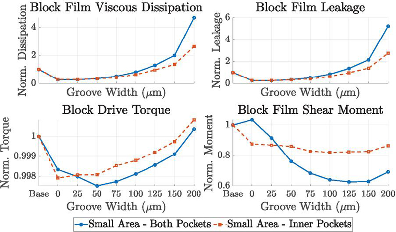
Figure 31 LSHP – small area: normalized loss components
[Pocket Width 0.4 mm, Pocket Depth 0.3 mm].
4.4 Effect of Hydrostatic Pocket Size on Block Performance
4.4.1 Pocket area
The cross-sectional area of the hydrostatic pockets is a key design parameter. Groove sizes of 0, 25, 75, and 150 m are selected based on the findings in Section 4.3, as they provide important insights into block performance. The analysis focuses on the low-speed, high-pressure condition for both the Large Area–Both Pocket and Large Area–Inner Pocket configurations, with pocket area varied by keeping the angular span constant while modifying the pocket width.
The performance trends associated with the pocket area are consistent across all tested groove widths; hence, only the 75 m groove results are presented as a representative case. As shown in Figure 32, reducing the pocket area diminishes hydrostatic support, lowering the minimum gap height and increasing the maximum gap height, which promotes block tilt and solid-body contact with the valve plate that can be seen in Figure 33, risking surface damage.
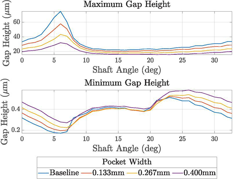
Figure 32 LSHP – large area – inner pocket: gap heights, ,
[Groove Width 75 m, Pocket Depth 0.3 mm].
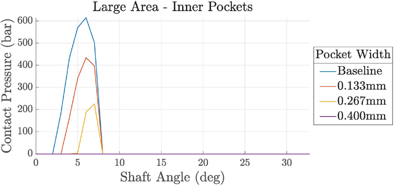
Figure 33 LSHP – large area – inner pocket: max contact pressure,
[Groove Width 75 m, Pocket Depth 0.3 mm].
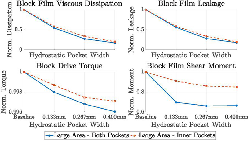
Figure 34 LSHP – large area: normalized loss components
[Groove Width 75 m, Pocket Depth 0.3 mm].
Increasing the pocket area shortens the duration and severity of contact, while simultaneously reducing torque and leakage and improving viscous losses. While larger pockets improve performance, a potential upper limit to pocket size has not been identified within the range considered.
4.4.2 Pocket depth
Lastly, variations in pocket volumes—achieved by keeping the same width and angular span while changing the depths from 3 mm to 0.03 mm are examined, with no significant differences observed.
5 Discussion
This study’s findings align with Achten et al.’s experimental work on Floating Cup pumps with hydrostatic pocket integration, demonstrating that the addition of hydrostatic pockets can create a more uniform film thickness, reduce viscous power loss, enhance cylinder block stability, and mitigate substantial solid-body contact on the sealing land [2]. This paper examines multiple hydrostatic pocket configurations in addition to Achten et al.’s study, confirming that the pressure distribution in the lubricating interfaces and the pressure in the pockets show that the hydrostatic pockets provide a dynamic and passive stabilizing effect to the cylinder block.
The placement of hydrostatic pockets is a critical design consideration. Although it may seem intuitive that positioning pockets on the outer sealing land would generate larger balancing moments, our results suggest that the squeeze and wedge effects in the low gap height region already generate sufficient pressure, diminishing the pockets’ influence. Instead, placing the hydrostatic pockets on the inner sealing land can supplement lubrication where hydrodynamic effects are the weakest. This finding is consistent across all four operating conditions simulated, and interestingly, in Achten et al.’s experimental study, only inner hydrostatic pockets were employed [2]. When the hydrostatic pockets are positioned farther from the displacement chamber, namely, the Large Area – Inner Pockets and Large Area – Both Pockets cases, the highest reductions in power losses are yielded (Table 5) and metal-to-metal contacts are avoided (Figure 12). Furthermore, since the Large Area – Inner Pockets and Large Area – Both Pockets configurations exhibit similar performance in all aspects, the Large Area – Inner Pockets setup alone is sufficient when considering manufacturing cost-effectiveness.
The present study shows that groove size directly governs the inflow regulation into the hydrostatic pockets and thereby influences both block stability and energy losses. The grooves have an isosceles triangular cross-section, with their width equal to their height. Very small grooves (including the no-groove case) produce nearly identical behavior, since the inflow is dominated by leakage through the lubricating film rather than the groove itself. This allows the pockets to retain pressure by balancing inflow and outflow, though under certain operating conditions, the reduced hydrostatic compensation can lead to solid-body contact. Notably, even the 0 m case outperforms the baseline, as the pockets provide additional hydrostatic support beyond the diffuse pressure gradient from the high-pressure port. Medium groove sizes, around 75 m in width, consistently provide the best balance across all five operating conditions and both hydrostatic pocket configurations. This groove size is in a similar order of magnitude, but a bit smaller than the grooves tested in Achten et al.’s experimental study, though that was performed on a different type of piston pump [2]. In this range, torque and viscous dissipation are significantly reduced without permitting excessive leakage, and block stability remains high. As the groove size continues to increase, however, hydrostatic support lifts the block excessively, leading to tilting that drives high leakage and elevated viscous dissipation, in some cases approaching the baseline behavior. These findings confirm that the stabilizing effect of hydrostatic pockets is not linearly improved by increasing groove size; rather, the groove functions as a passive, orifice-like feature that must be optimized to balance hydrostatic and hydrodynamic contributions to block stability.
To assess whether performance also depends on the pairing of groove size and pocket position, the Small Area – Both Pockets and Small Area – Inner Pockets configurations were simulated at low-speed, high-pressure conditions. Consistent with Section 4.2, for any given groove width these configurations show greater tilting, higher contact pressure (Figures 29–30), and increased leakage, torque loss, and viscous dissipation (Figure 31) compared with the Large Area results (Figure 23). Pairing a smaller groove (50, m) with the Small Area cases can reduce losses below those of Large Area configurations with larger grooves (m), but the preferred design remains Large Area – Both Pockets or Large Area – Inner Pockets combined with smaller grooves.
Lastly, the size of the hydrostatic pockets is also a critical design parameter. At low speed and high pressure, reducing the pockets’ cross-sectional area diminishes the hydrostatic compensation until its stabilizing benefit effectively disappears. While increasing the area continues to enhance support, a practical upper limit may exist, though it is not identified within the range considered. Meanwhile, altering the pocket volumes by reducing their depths from 3 mm to 0.03 mm has no appreciable effect on the results.
6 Conclusion
This study showcases the effectiveness of hydrostatic pockets by improving the lubrication performance of piston-type machines, supporting and extending Achten et al.’s [2] experimental findings. Using advanced computational modeling techniques, the impact of the hydrostatic pockets is analyzed under several operating conditions, which result in improved gap height uniformity, pressure distribution, contact behavior, and overall efficiency; more generally, the addition of hydrostatic pockets allows piston-type machines to broaden their range of operating speeds.
Out of all the setups simulated, placing the hydrostatic pockets on both sides of the cylinder block sealing land and farther away from the displacement chambers achieves the best performance in maintaining gap height, preventing metal-to-metal contact, and reducing power loss. However, the performance is similar when only placing the pockets on the inner sealing land; thus, this configuration represents the most balanced choice. The results demonstrate the importance of the placement of the hydrostatic pockets for lubrication performance and provide guidance for designing future piston-type machines.
With respect to groove size, very small grooves (including no groove) behave similarly, as the lubricating film effectively regulates flow. Medium grooves (75 m width) provide the best balance of stabilization, leakage, and energy loss. Larger grooves increase gap height and block tilt, causing higher leakage and, in some cases, contact. Regarding pocket position groove size pairing, Large Area – Both Pockets and Large Area – Inner Pockets consistently outperform the Small Area configurations at all groove sizes, showing less tilting, lower contact pressure, and reduced losses.
For the pocket size, larger cross-sectional areas enhance hydrostatic compensation and block stability, while smaller areas diminish the effect. A practical upper limit may exist, but it is not identified in this study. Lastly, the pocket volume is found to have no significant effect on the pump’s performance.
However, the study also has limitations. Future research will refine the simulation model by including piston-seal/cylinder-bore lubricating interface and the FEM plus thermal deformation to further improve prediction accuracy. Experimental tests on the Floating Piston pump with the incorporation of hydrostatic pockets are also intended to validate the simulation results and help bridge the gap between theory and practice.
Acknowledgement
Linköping University’s contribution was funded by the Swedish Electromobility Centre with grant number 13070 and the Swedish Energy Agency (Energimyndigheten) with grant number P2023-00594. The share of simulations run at Linköping University were enabled by resources provided by the National Supercomputer Centre (NSC), funded by Linköping University.
Nomenclature
| Designation | Denotation | Unit |
| Mean velocity of the fluid in the interface | m/s | |
| Surface velocities of the top and bottom plates | m/s | |
| Velocity of the inertia frame | m/s | |
| Velocity components in the interface | m/s | |
| Inertia tensor of the block frame | kg-m2 | |
| Angular velocity of the block frame | rad/s | |
| Load force on the cylinder block | N | |
| Hydrostatic compensation force | N | |
| Radial force due to wedge-shaped fluid in displacement chamber | N | |
| Sum of forces in inertia frame | N | |
| Sum of moments acting on the block frame | N-m | |
| Surface roughness parameter | ||
| Bulk modulus | Pa | |
| Dynamic viscosity | Pa-s | |
| Fluid density | kg/m3 | |
| Hydrostatic compensation ratio | – | |
| Time | s | |
| Viscous power loss | W | |
| Total power efficiency loss | – | |
| Pressure | Pa | |
| Outlet and inlet pressures | Pa | |
| Pressure difference across the orifice | Pa | |
| Mass of the cylinder block | kg | |
| Mass flow rate | kg/s | |
| Discharge coefficient | – | |
| Orifice area | m2 | |
| Volume of hydrostatic pocket | m3 | |
| Displacement volume | m3 | |
| Lubricating film thickness | m | |
| Mixed lubrication flow factors | – | |
| Dissipation function | – | |
| Radial coordinate in polar form | m | |
| Radius of the sealing ring | m | |
| Tilt angle of the piston plate | rad | |
| Low speed high pressure | – | |
| Low speed low pressure | – | |
| High speed low pressure | – | |
| High speed high pressure | – | |
| Medium speed medium pressure | – |
References
[1] J. Ivantysyn and M. Ivantysynova. Hydrostatic Pumps and Motors, Principles, Designs, Performance, Modeling, Analysis, Control and Testing. Academia Books International, New Delhi, India, 2001. ISBN 8185522162.
[2] P. Achten, R. Mommers, J. Potma, and J. Achten. Experimental investigation of a hydrostatic bearing between barrels and port plates in floating cup axial piston pumps. In BATH/ASME 2020 Symposium on Fluid Power and Motion Control, 2020. https://doi.org/10.1115/FPMC2020-2712.
[3] Liselott Ericson and Jonas Forssell. A novel axial piston pump/motor principle with floating pistons: Design and testing. In BATH/ASME 2018 Symposium on Fluid Power and Motion Control, FPMC2018. American Society of Mechanical Engineers, 2018. https://doi.org/10.1115/FPMC2018-8937.
[4] P. Achten and S. Eggenkamp. Barrel tipping in axial piston pumps and motors. In Proceedings of the 14th International Fluid Power Conference, volume 144, pages 381–391, 2017. https://ep.liu.se/ecp/144/038/ecp17144038.pdf.
[5] M. Ernst and A. Vacca. Hydrostatic vs. hydrodynamic components of fluid pressure in the tribological interfaces of axial piston machines. Tribology International, 157:106878, 2021. https://doi.org/10.1016/j.triboint.2021.106878.
[6] R. Chacon and M. Ivantysynova. An investigation of the impact of the elastic deformation of the endcase/housing on axial piston machines cylinder block/valve plate lubricating interface. In Proceedings of the 10th IFK International Conference on Fluid Power, volume 1, pages 283–294, Dresden, Germany, 2016. https://core.ac.uk/download/pdf/236373067.pdf.
[7] Daniel Hasko, Lizhi Shang, Eric Noppe, and Emmanuel Lefrançois. Virtual assessment and experimental validation of power loss contributions in swash plate type axial piston pumps. Energies, 12(16), 2019. https://doi.org/10.3390/en12163096.
[8] Ahmed Shorbagy, Roman Ivantysyn, and Jürgen Weber. Holistic analysis of the tribological interfaces of an axial piston pump – focusing on the pump efficiency. Chemical Engineering and Technology, 46(1):5–13, 2023. https://doi.org/10.1002/ceat.202200450.
[9] Svenja Horn, Roman Ivantysyn, and Jürgen Weber. Tribo-optimized lubricating interfaces in hydrostatic pumps with surface shaped slippers. In The 13th International Fluid Power Conference, 13. IFK, June 13-15, 2022, Aachen, Germany, pages 37–51, 2022.
[10] Roman Ivantysyn, Svenja Horn, and Jürgen Weber. Design of a lead-free slipper bearing for low speed axial piston pump applications. International Journal of Fluid Power, 25(2):183–202, 2024. https://doi.org/10.13052/ijfp1439-9776.2524.
[11] Ashley Busquets. An Investigation of Micro-Surface Shaping on the Piston / Cylinder Interface of Axial Piston Machines. Phd thesis, Purdue University, 2018.
[12] Stephan Wegner, Stefan Gels, and Hubertus Murrenhoff. Vergleich analytischer berechnungsmethoden des entlastungsgrades im kolbentrommel-steuerspiegel-kontakt in axialkolbenmaschinen. O+P Fluidtechnik, 11-12/2017:60–69, 2017.
[13] N. D. Manring. Tipping the cylinder block of an axial-piston swash-plate type hydrostatic machine. Transactions of the ASME, 122:216–221, 2000. https://doi.org/10.1115/1.482445.
[14] Andrea Vacca and Germano Franzoni. Hydraulic Fluid Power: Fundamentals, Applications, and Circuit Design. John Wileys and Sons, 2021. ISBN 9781119569138.
[15] M. Zecchi and M. Ivantysynova. A novel approach to predict the cylinder block/valve plate interface performance in swash plate type axial piston machines. In Bath/ASME Symposium on Fluid Power and Motion Control, Bath, UK, 2012.
[16] Jonathan Baker and Monika Ivantysynova. Advanced surface design for reducing power losses in axial piston machines. In The 11th Scandinavian International Conference on Fluid Power, SICFP’09, June 2-4, 2009, Linköping, Sweden, 2009.
[17] Monika Ivantysynova and Jonathan Baker. Power loss in the lubricating gap between cylinder block and valve plate of swash plate type axial piston machines. International Journal of Fluid Power, 10(2):29–43, 2009. https://doi.org/10.1080/14399776.2009.10780976.
[18] Raghavendra Reddy, Roman Ivantysyn, Mathias Rauschenberger, and Jürgen Weber. Advanced micro-surfacing: Tribological optimization for variable-speed hydraulic drives. In Proceedings of the ASME 2025 International Desing Engineering Technical Conferences and Computers and Information in Engineering Conferences IDETC-CIE2025, August 17–20, 2025, Anaheim, CA, USA, 2025.
[19] P. A. J. Achten, T. L. v. d. Brink, and G. E. M. Vael. A robust hydrostatic thrust bearing for hydrostatic machines. In Proc. 7th International Fluid Power Conference (IFK), pages 100–112, Aachen, Germany, March 22–24 2010.
[20] T. Ransegnola. A strongly coupled simulation model of positive displacement machines for design and optimization. PhD Dissertation, Purdue University, West Lafayette, Indiana, 2020.
[21] Linköping University (Division of Fluid and Mechatronic Systems). Hopsan. https://liu.se/en/research/hopsan, accessed 2025-02-17.
[22] Thomas Heeger. Design of Electro-Hydraulic Energy Converters : With Focus on Integrated Designs and Valve Plate Rotation, volume 1971 of Linköping Studies in Science and Technology. Licentiate Thesis. Linköping University Electronic Press, Linköping, 2023. ISBN 9789180752435, 10.3384/9789180752442, https://urn.kb.se/resolve?urn=urn:nbn:se:liu:diva-194262.
[23] B. J. Hamrock, B. J. Schmid, and B. O. Jacobson. Fundamentals of Fluid Film Lubrication. CRC Press, 2004. https://ntrs.nasa.gov/api/citations/19910021217/downloads/19910021217.pdf.
[24] N. Patir and H. S. Cheng. An average flow model for determining effects of three-dimensional roughness on partial hydrodynamic lubrication. J. Lubr. Technol., 100(1):12–17, 1978. https://doi.org/10.1115/1.3453103.
[25] N. Patir and H. S. Cheng. Application of average flow model to lubrication between rough sliding surfaces. J. Lubr. Technol., 101(2):220–229, 1979. https://doi.org/10.1115/1.3453329.
[26] C. Wu and L. Zheng. An average reynolds equation for partial film lubrication with a contact factor. J. Tribol., 111(1):188–191, 1989. https://doi.org/10.1115/1.3261872.
[27] A. Schenk and M. Ivantysynova. An investigation of the impact of elastohydrodynamic deformation on power loss in the slipper swashplate interface. In Proc. 8th JFPS International Symposium on Fluid Power, Okinawa, Japan, October 2011. https://jfps.or.jp/souko/proceedings/okinawa2011/pdf/1C2-5.pdf.
Biographies

Haotian Han received his B.Sc. and M.Sc. degrees in Aeronautical and Astronautical Engineering from Purdue University in 2024. He is currently pursuing a Ph.D. degree in Mechanical Engineering at Purdue University, conducting research at the Maha Fluid Power Research Center. His work primarily focuses on developing and validating fluid–structure interaction models for elastohydrodynamic lubrication in axial piston machines.

Thomas Heeger received his PhD in Fluid and Mechatronic Systems at Linköping University, Sweden, in 2025. His research interests include hydraulic pumps and their electrification.

Lizhi Shang received his Ph.D. from Purdue University in 2018. He is currently an Assistant Professor of Mechanical Engineering and Agricultural & Biological Engineering at Purdue University. His research focuses on the design and modeling of hydrostatic pumps and motors, hydrodynamic pumps and turbines, fluid power systems, and advanced computational and experimental tribological analysis.

Liselott Ericson received her Ph.D. in Hydraulics at Linköping University (LiU), Sweden, in 2012. She currently works as a professor at Fluid and Mechatronic Systems at LiU. Her research interests include pump and motor design, electro-hydraulic systems, and modeling and simulation.
International Journal of Fluid Power, Vol. 27_1, 127–174
doi: 10.13052/ijfp1439-9776.2715
© 2026 River Publishers