EHAs in Mobile Machinery: Simulative Evaluation of a Control Scheme Including Load-holding Capability Using Active Hysteresis and Throttle Control
Felix Figge* and Katharina Schmitz
RWTH Aachen University, Institute for Fluid Power Drives and Systems, Aachen, Germany
E-mail: felix.figge@ifas.rwth-aachen.de; katharina.schmitz@ifas.rwth-aachen.de
*Corresponding Author
Received 21 September 2025; Accepted 18 December 2025
Abstract
In recent years, the electrification of mobile machinery has advanced. One crucial issue is that the energy density of the associated storage solutions is lower, requiring more space on the machines or more frequent recharging. To compensate for this the hydraulic system must be more efficient and sustainable. In this context, the use of decentralized electro-hydrostatic actuators (EHA) shows high potential. However, they are not yet widely used. The reasons for this are likely higher initial component costs, worse dampening, and the high cost of implementing necessary control software.
This paper presents a simulation-based evaluation of an electro-hydrostatic actuator with a hydraulic high-speed unit intended for use in mobile machinery. The circuit layout was selected based on cost considerations and incorporates load-holding capability. Furthermore, the load-holding valves are a key aspect of the control scheme. They are used to introduce a small amount of active throttling on the outflow side of the cylinder while energy is supplied to it. This extends the load pressure range in which the hydraulic unit is pumping and enables full operational coverage of all working conditions, which would otherwise be impossible. The developed controller synchronizes the valves’ switching times with motor speed to enhance system performance and prevent excitation.
The controller is linked with a lumped parameter model of the hydraulic circuit and validated based on test cases that focus specifically on the quadrant switches, as well as on a measured dig and dump cycle. The results qualitatively demonstrate the excellent performance of the EHA, with mostly brief and minor velocity deviations during quadrant switching. The combination of the developed EHA and corresponding controller achieves good position tracking during the load cycle once drift due to inherent control delays is compensated for by a simple P-controller, representing the machine operator adjusting to the system response. This reduces the maximum RMSE of position deviation from 163 mm to 42 mm.
In conclusion, the results demonstrate the functionality of the developed EHA and encourage further investigation, particularly experimental validation, to confirm the findings.
Keywords: EHA, 4Q-operation, recuperation, electrification, active throttling, hysteresis control.
1 Introduction & State of the Art
The change of the prime mover from a combustion engine to an electric motor can be considered the most important change in mobile hydraulics of the past decades. Historically, many mobile machines use a centralized hydraulic pressure supply, which distributes the power via valves and fluid lines to the actuators. While this approach is cost-effective in terms of initial costs, it results in high valve throttle losses. These mainly originate from different actuators requiring various pressure levels. The increased focus on energy conservation in addition to the limited amount of energy available in battery-powered machinery requires the hydraulic system to be more efficient and sustainable.
In this context, the use of decentralized electro-hydrostatic actuators (EHA) is highly promising. The use of a dedicated pump and motor for each actuator circumvents the losses arising from throttling between the highest pressure level and the lower levels required by the other actuators. While EHAs are more frequently used for industrial applications, widespread use in mobile machinery has not been achieved. Reasons for this are likely the higher initial component cost, the increased installation space, worse dampening – directly linked to the reduced system losses – as well as higher investment in the implementation of the required control software. The currently higher component costs of EHAs in comparison to a load-sensing system mainly arise from the additionally required prime movers and hydraulic units. Furthermore, to facilitate the easy integration of the EHA into existing mobile machinery the installation space must be small. The total installation space required for the EHA can be reduced by increasing the electric motor’s rotational speed and thereby also reducing the pump’s size due to a smaller required displacement volume. Pietrzyk and Roth have conducted research in this area, including investigating the use of an intermediate gear stage [1–5]. This paper is based on a project that continues the work of developing a high-speed, closed-circuit EHA with recuperation and load-holding capabilities for use in mobile machinery.
Closed-circuit EHAs using a single pump are known to suffer from undesirable behavior during certain operating conditions – especially, during switches between operating quadrants. Often, pressure feedback is used to increase the overall dampening of the system [6, 7], which is generally too low for good system behavior. Williamson and Ivantysynova [8] developed a predictive observer to provide sufficient lead time for feed-forward control of pump displacement in a skid-steer and allow four-quadrant operation. However, this approach was aimed at dealing with excessive phase lag and rendered the feedback control ineffective at handling mode-switching oscillations. They later concluded that the main problem is the interaction between moving mass and the compressible fluid which acts like a mass-spring-damper [6]. The unequal actuator areas intensify any excitation, due to the pump still providing the flow rate required by the other cylinder chamber, sending the system back and forth between quadrants [6, 7]. Increasing the system dampening is therefore recommended to damp the oscillations and prevent mode switches. Therefore, pressure feedback is implemented. Michel further calculated a maximum allowable acceleration to prevent mode switches [7]. Wang et al. [9] used electrically actuated proportional valves in combination with a control algorithm to introduce leakage in critical operation conditions to selectively increase dampening and prevent oscillation. This compensation is only active near critical operating conditions at low loads. They also use the valves to ensure the accumulator is connected to one cylinder side in case of oscillations of the additionally used shuttle valve. A mechanical variant of adding leakage under critical conditions was presented by Çalışkan et al. [10]. Here, an underlapped shuttle valve was used, foregoing additional electrical valves, sensors or control algorithms. Imam et. al introduced a new valve type they called “limited throttling valve” to prevent oscillation in the critical region of a circuit using two pilot operated check valves (POCV) [11, 12]. The valve is designed to restrict the cylinder flow only at low loads near critical operating conditions. Their simulation results show no oscillations in all operating conditions. They also show that the critical zone and oscillation amplitudes can be reduced by applying different charge pressures to both cylinder sides [12]. Costa and Sepehri [13] introduced a new four-quadrant definition based on the cylinder load pressure instead of the pressure difference over the pump. They concluded that this was the main reason for the poor behavior of previous circuits and introduced a new circuit to account for their new quadrant definition. However, Gøytil et al. [14] showed that the proposed circuit can still suffer from unwanted mode switches under certain conditions due to dynamic considerations. Instead, they suggest using an observer to calculate a modified force estimate to decide the valve states, eliminating the unwanted mode switches. Unlike the previous works, which primarily focused on hydraulic implementations, their approach is software-based. The observer excludes forces introduced by valve switches and acceleration. Their strategy, however, required a certain accumulator pressure (in their case 30 bar) to prevent cavitation, which is inappropriate for certain circuits due to pressure limits. Kärnell and Ericson [15] investigated hysteresis control to prevent unwanted mode switches and concluded that the pressures should be sensed in such a way that the difference is unchanged after a mode switch. Even then, switches can occur, but active hysteresis control reduces that risk if reservoir pressure is sufficient.
The approach presented in this paper uses the cylinder load pressure definition by [10, 13] and implements active throttling [12, 15] to allow full coverage of the four-quadrants in an excavator. To reduce mode switches due to small pressure oscillations, an active hysteresis is added [15]. The control approach attempts to further minimize the spikes in cylinder velocity during quadrant switches by decoupling the cylinder from the pump using the incorporated load-holding valves.
2 Circuit
Many circuits for EHAs are known in literature. In [16] Ketelsen et al. provide an overview and classification. Regarding the aim to integrate EHAs into mobile machinery, particularly excavators, certain circuit layouts are excluded due to the following requirements: minimizing initial costs, achieving a wide range of operating conditions with high overall efficiency, and enabling the prime movers to stop completely. The next section introduces the selected circuit and derives its operating boundaries. Afterwards, the developed control scheme will be presented and validated using a lumped parameter simulation.
Internal gear pumps with fixed displacement, which have fewer and simpler parts than piston pumps, should be used, as this generally reduces cost. Similarly, due to the expense associated with variable speed prime movers – which are required for flow adjustment of fixed displacement hydraulic units – they shall be limited to one. Circuits using more than one pump were considered to allow for a larger variety of layouts. As the application in mobile machinery has uncertain operating conditions, the EHA must be able to operate in all four quadrants. To still achieve high efficiency, the EHA shall be able recuperate energy. The EHA must be encapsulated, leaving only the electrical and mechanical connections exposed. Internal storage is required to hold the differential fluid volume of the cylinder. To enable the prime mover to stop completely and prevent overheating and minimize wear on the hydraulic unit, integrating load-holding valves was deemed necessary.
Based on these restrictions, four circuits were selected for closer investigation. The circuits were introduced in [16] and all but one use a single fixed displacement pump. The first circuit uses pilot-operated check valves (POCV) to accommodate the differential flow rate of the cylinder [17] as well as to allow load-holding [18]. The second circuit uses a cylinder with multiple chambers, allowing for a structural design close to a differential cylinder with equal rod and piston areas [19]. The differential flow is thereby eliminated. The third circuit utilizes two pumps with a displacement ratio equal to the cylinder area ratio to provide appropriate flow rates [20]. The final, ultimately selected circuit uses electrically actuated valves to manage differential flow rates [14] and load-holding.
2.1 Selected Circuit Layout
The circuit shown in Figure 1 was selected due to its use of a single hydraulic unit, a standardized cylinder, and highly customizable software control. The circuit consists primarily of a variable high-speed prime mover, a four-quadrant internal gear unit, and a differential cylinder. An accumulator stores the differential volume of the retracted cylinder rod length and provides sufficient charge pressure for the hydraulic unit, especially at high speeds. To enable differential flow to return to the accumulator, the circuit includes two electric switching valves, Diffrod and Diffpist. These valves are referred to as differential valves in the following text. Electric actuation enables precise control over the timing of the connection between the pump ports and the accumulator. The load-holding valves, LHrod and LHpist, are proportionally adjustable. Oil flowing back into the accumulator is filtered by use of two additional check valves, CVacc and CVfilter. Check valves in parallel with the load-holding valves (CVLH) and the differential valves are necessary to prevent cavitation in the pump and cylinder. During circuit design, it was determined that separate oversized check valves were necessary to maintain a low enough pressure drop to prevent cavitation, given the commercially available valves. This was necessary due to the accumulator’s pressure level, which is limited to 10 bar by the hydraulic unit’s shaft sealing. Although an electric motor with a rotor running in oil could solve this issue because it does not require a shaft seal, it would introduce higher shear losses.
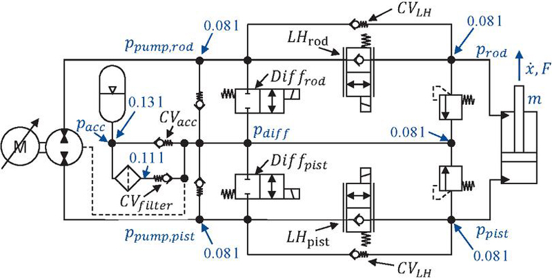
Figure 1 Circuit layout, pressures and fluid volumes.
The operation of a cylinder can be divided into the well-known four-quadrants based on two criterion, the cylinder velocity as well as the cylinder load, as shown in Figure 2. While the definition of the cylinder velocity is straightforward, different approaches for the load definition exist. They range from the pressure difference between the pump ports, the pressure difference between the cylinder chambers and the load pressure following Equation (1), where represents the cylinder area ratio. The main advantage of the load pressure definition is the consideration of only the active forces on the cylinder, as described by Equation (2). Therefore, the load pressure as defined by [10, 13] is used as the second criterion for the quadrant definition. External force F in Figure 2 is only used for clarification of load direction and does not represent the used criterion.
| (1) | |
| (2) |
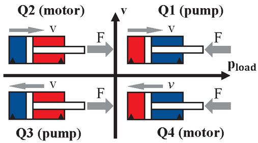
Figure 2 Four-quadrant plane.
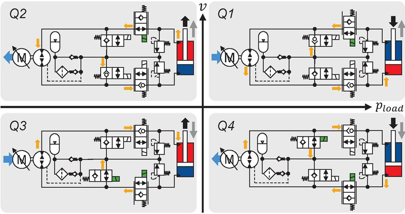
Figure 3 Valve actuation and oil flow in all four quadrants.
In Figure 3, the actuation of valves and oil flow in all four quadrants of operation is shown. Active valves are marked with a green coil symbol and the oil flow is shown with orange arrows. A simplified circuit layout with integrated check valves is used for clarity. Following the quadrant definition from Figure 2 the cylinder moves outward in Q1 and Q2 (dark grey arrows) and inward in Q3 as well as Q4. Q1 and Q3 are the pumping quadrants in which the hydraulic unit is supplying energy into the circuit, marked with a light blue arrow towards the hydraulic unit. In Q2 and Q4 the unit works as a motor, extracting energy. Quadrant switches based on a reversal of cylinder movement (Q1Q4 or Q2Q3) are controlled by a change of motor speed and can therefore be more easily managed by the control scheme.
Conversely, switching operating quadrants based on a direction reversal of the external load (Q1Q2 or Q3Q4) is more difficult because the exact time of the change in direction cannot be predicted. In both cases, a change in motor speed is required due to the different cylinder areas. Ideally, the speed change would happen instantaneously, but it is limited by motor torque and inertia. The positions of the load-holding valves also need adjustment. Additionally, switches Q3Q4 require a differential valve actuation, as shown in Figure 3. To avoid poor system performance due to unwanted system states, the valve actuation must be synchronous to the motor speed change.
The subsequent section will provide a description of how these challenges are addressed, building upon the in-depth explanation of circuit behavior and the derivation of existing operational boundaries.
2.2 Circuit Behavior and Boundaries
A similar concept to the one presented in this section was done in [6], regarding a circuit without load-holding valves and differential flow handling by pilot-operated check valves.
First, the effect of the accumulator pressure is examined. Neglecting all pressure drops across valves as well as all other forces, the accumulator pressure results in an active pushing force on the cylinder rod. The cylinder is moving outward without energy input from the pump, corresponding to an operation in Q2. Substituting the accumulator pressure into Equation (1) for both cylinder pressures yields the related load pressure, given by Equation (3).
| (3) |
is greater than zero for all positive accumulator pressures, thereby representing a new boundary between motor and pump operation. This can be verified for the other quadrant boundaries by considering an external force pushing the cylinder inward. The cylinder will only move inward without assistance from the pump (Q4) if the external force is greater than the accumulator pressure’s outward pushing force. In turn, this would result in a load pressure larger than , since would rise. Figure 4 shows the new boundary as a blue rectangle for an accumulator pressure between 4.6 bar and 10 bar. The representation as rectangle follows since the accumulator pressure changes during charging and discharging.
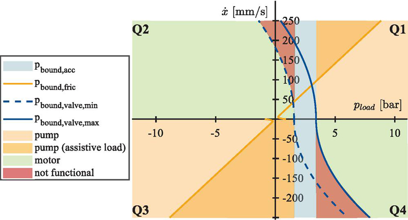
Figure 4 Load pressure boundaries of the circuit.
Next, the quadrants Q1 and Q3 are considered, where the pump provides power. If the pressure drop across the load-holding valves is neglected, steady-state movement of the cylinder is assumed and no external force is applied, the load pressure originates only from the cylinder friction (see Equation (2)). Here, neglecting the pressure drop across the valves is not strictly necessary. A pressure increase on the outflow cylinder side due to the valve resistance, will be canceled out in the load pressure calculation by the necessary pressure increase on the inflow side due to the force balance. This has no further ramifications except for an increase in pump pressure. The load pressure required for motion with a specific velocity follows from Equation (4) in Q1 and Equation (5) in Q3 for the load-free condition. The corresponding boundaries are drawn in orange in Figure 4 and are calculated by means of the friction model used in the simulation as defined by Equation (8) and Equation (9) in combination with the parameters given in Table 1.
| (4) | |
| (5) | |
| (8) | |
| (9) |
If the external force is pushing in Q1 and therefore has a negative sign, the load pressure will be higher than in the load-free condition, as stated by Equation (10). Therefore, a load pressure below the load-free condition can only be achieved if the external force assists the motion. The same conclusion can be made for Q3 by using Equation (11) with the only difference being that an assistive load results in a higher load pressure due to the reversed movement direction. Both areas are marked with the darker orange shade in Figure 4. The boundary thereby can be used to determine if the external force is assistive – provided the friction force is known with sufficient accuracy. The only consequence function-wise is that the load pressure will increase along the boundary line if the velocity is increased while no assistive load is applied. All velocities within the quadrant can still be achieved.
| (10) | ||
| (11) |
Lastly, the quadrants with motor operation are investigated. Contrary to the previous case, energy is now provided by the cylinder and not the pump. The flow rates through the load-holding valves can be described by the orifice Equation (12), which is further related to the cylinder velocity by Equation (13) considering the currently loaded cylinder side. is the active flow area depending on the valve position s. It can be concluded that the cylinder velocity will be limited for low pressure differences and, therefore, small external loads.
| (12) | |
| (13) |
At low loads the cylinder velocity is not controlled by the rotational speed of the pump but by the orifice flow instead. The outflow of the cylinder is then smaller than the flow rate given by pump speed. As result the check valves between accumulator and pump open, preventing cavitation and setting the pressure at the pump inlet close to the accumulator pressure . The pump outlet pressure is also close to because the corresponding differential valve is actuated and connects to the accumulator. Furthermore, the unloaded cylinder chamber pressure is at the same level, , as the connected check valve also opens, preventing cavitation as well. Depending on the operating quadrant, the loaded cylinder side switches, resulting in Equation (14) for Q2 and Equation (15) for Q4 to calculate the boundary load pressure following the previous explanations.
| (14) | ||
| (15) |
By rearranging Equations (14) and (15) to Equations (16) and (17) relations between the pressure drop and are derived. The second terms in the parenthesis of Equation (16) and (17) are equal to , showing a dependence on the accumulator pressure. By inserting Equations (16) and (17) into Equation (13) a correlation between cylinder velocity and load pressure is derived, which is shown in Figure 4 as blue lines. These lines mark the required load pressure to achieve the respective cylinder velocity. The solid line marks the maximum accumulator pressure and the dashed line the minimum accumulator pressure. If the load pressure falls “below” the current boundary – taking into consideration the different signs in Q2 and Q4 – the velocity will sink along the boundary.
| (16) | ||
| (17) |
In conclusion, an operation in motor mode is only possible above the boundary. The corresponding velocities and load pressures are marked green in Figure 4. On closer inspection, two areas between and remain, marked red in Figure 4, where operation of the circuit is not possible. Here the assistive load is not large enough to achieve the required flow rate through the load-holding valve and the cylinder velocity remains too low. Valves with smaller pressure drops reduce this area but do not remove the boundary completely. This behavior is unacceptable for the operation in mobile machinery since it would result in a large and prolonged deviation from the control signal.
An expansion of Q1 and Q3 and therefore the supply of energy from the pump in only these areas is theoretically possible. It requires the throttling of the cylinder outflow to allow the pump to control the cylinder velocity by providing flow rate in the otherwise unloaded cylinder chamber. Without fitting throttling, the cylinder would accelerate due to the external load, therefore the valve characteristics need to be known precisely for this approach, which is generally not the case. Additionally, the characteristics change during operation – for example, due to temperature.
For example, if the load pressure lies within the red area derived from the assumed pressure drop, the hydraulic unit would be used as pump to provide energy. Assuming the control anticipates a pressure drop larger than actually required, a larger than expected flow rate would occur at the boundary, resulting in higher cylinder velocity. Thereby pump control is lost since the pump flow is smaller than what is required by the cylinder. There are only two ways to slow down the cylinder in this scenario. One would require the hydraulic unit to work in motor mode and use it to control the cylinder velocity – which directly contradicts the previous assumption that the unit is pumping. Alternatively, the pressure drop across the valve could be increased to lower the flow rate out of the cylinder. Since it was assumed that the valve characteristics are not known precisely enough, a closed-loop control would be required. The required position sensor would increase the cost of the EHA and therefore, this approach is discarded.
If an expansion of the pumping quadrants further than the red marked areas is accepted, a simpler approach, following the same principle, is possible. The valve is not actuated to match the pressure drop to the currently required flow rate, but to achieve a fixed pressure drop. This is discussed in [15] as a possible way to introduce hysteresis to prevent unwanted quadrant switches, called “active throttling”. Unfortunately, the authors conducted no further investigation. A similar approach is also introduced in [12] as “selective throttling” with specifically designed valves that increase throttling in the critical region to reduce oscillations. As was discussed before, active throttling is needed to allow the investigated circuit with load-holding valves to cover the full operational range and not to introduce hysteresis or reduce oscillations, so that this approach is based on a different motivation. The fixed pressure drop must be larger than the pressure drop of the load-holding valves at the maximum flow rate and full opening. Otherwise, the required flow rate at high cylinder velocity cannot be achieved. The fixed pressure drop results in a larger area in which the hydraulic unit can be operated in pumping mode without loss of control over the cylinder velocity. Pump control is lost when the provided pump flow rate is insufficient, resulting in an opening of the check valves and a pressure level close to – approximated by . The pressure in the other cylinder chamber at the boundary equals – approximated by as well – plus the artificial pressure difference , as given by Equation (18) and Equation (20). By substitution of these into Equation (1), load pressure boundaries for Q1 (Equation (19)) and for Q3 (Equation (21)) are derived. At these boundaries, the external load accelerates the cylinder and the flow rate provided by the pump becomes insufficient. In Q3 the artificial pressure drop distributes across the load holding valve and the differential valve due to the flow back to the accumulator. The latter is neglected and is fully accounted for by the load-holding valve. The total pressure drop is therefore higher, achieving a conservative approach at the cost of energy efficiency. Since the flow rate is proportional to the cylinder velocity, the influence of the additional valve resistance is small at low velocities and increases with rising velocities. Again, the accumulator boundary is part of the equations resulting in a maximum and minimum boundary drawn as green lines in Figure 5 for set to 22 bar. Figure 5 thereby represents the new quadrant definition with expanded pumping quadrants and active hysteresis. While a reduction of above is possible, this option was discarded in favor of improved cylinder control.
| (18) | |
| (19) | |
| (20) | |
| (21) |
The control current required to actuate the valve is taken from a characteristic diagram that includes the pressure difference, the flow rate and the electric current. The flow rate is calculated from the requested cylinder velocity and the current pump speed. The boundary position is influenced by the accumulator pressure, which can be measured and compensated for. However, the characteristic diagram is generally inaccurate and deviations are unavoidable. Introducing an arbitrary virtual boundary respectively between and , at which the quadrant switch is initiated, introduces a safety margin to account for deviations. Furthermore, a slow PI-controller adjusts the load-holding valve position to achieve the desired pressure difference between the cylinder chamber and , thus circumventing the neglected pressure drop in Q3. Additionally, “active hysteresis” [15] is added to the switching boundaries so that small changes in load pressure will not result in a switch of the detected quadrant. The introduced hysteresis is shown in violet in Figure 5 with a width of 4 bar and is referenced to the defined virtual boundary . For example, for a positive cylinder velocity, the motor mode in Q2 starts if the load pressure falls below -10 bar. Afterwards, the EHA will switch back to pump mode (Q1) only if the load pressure increases above -6 bar. Negative load pressures are the result from higher pressures on the rod side as defined by Equation (1).
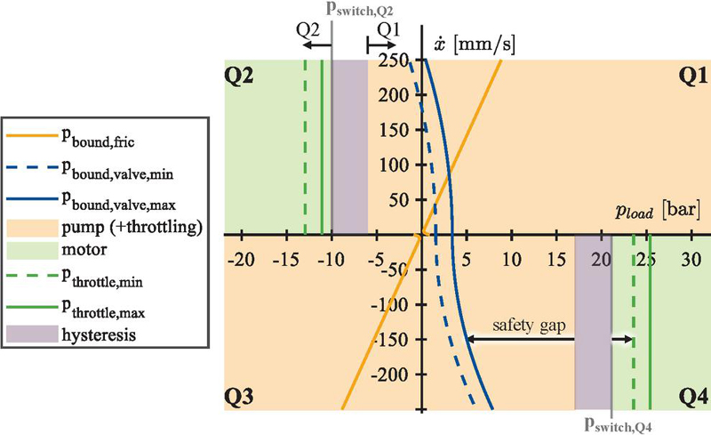
Figure 5 Load pressure boundaries of the circuit with active throttling and hysteresis.
The positioning of the virtual boundary, including hysteresis, determines a safety gap in terms of load pressure change before velocity control is lost. Exemplary safety gaps for Q4/Q3 are marked in Figure 5. For Q4Q3 the safety gap and therefore a reaction time starts when the load pressure falls below the left hysteresis boundary and ends when it reaches the valve boundary, where the cylinder will start to slow down. The hysteresis boundary is not positioned in the middle because the specific control is used for the arm of an excavator. Switches from Q1Q2, as well as Q3Q4, are unlikely during normal operation since the center of gravity cannot cross the top center position. More often the arm first lowers and then contacts the ground. Under sufficient load, this corresponds to a Q2Q1 switch. The position of the virtual boundary, the width of the hysteresis and the artificial pressure difference are therefore dependent on the application and need to balance safety gaps with increasing proclivity towards unwanted quadrant switches and energy efficiency.
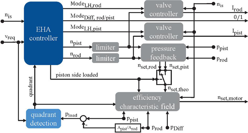
Figure 6 Top level of control scheme.
3 Control Scheme
Based on the load pressure boundaries shown in Figure 5 a control scheme is developed. The top level of the control is shown in Figure 6. The main component is the EHA controller that outputs the valve modes and the required rotational speed depending on the loaded cylinder side. The speed request is limited and adjusted by pressure feedback to reduce pressure oscillation [7]. Depending on the loaded cylinder side, one of the speed requests is fed into the characteristic field of the hydraulic unit, adjusted to compensate for volumetric losses and then output to the motor controller. The valve controllers output the current to actuate the load-holding valves based on different modes that are explained later. To reduce the number of pressure sensors, the low-pressure level of the hydraulic unit will be also approximated by instead of , since the check valve is sized to have a low pressure drop and neglecting the pressure drop over the differential valve in Q3. For clarity, the overload protection, which increases the pressure drop over the load-holding valves during motor operation if the electric motor gets close to its torque limit, was omitted from the schematic. This is essential at high speeds to prevent an uncontrolled acceleration of the cylinder as any acceleration reduces the torque capacity further.
The load pressure boundaries from Figure 6 are implemented in the state machine for quadrant detection, as shown in Figure 7. In addition to the well-known four-quadrants, a fifth state was added for the standstill of the EHA (Q0).
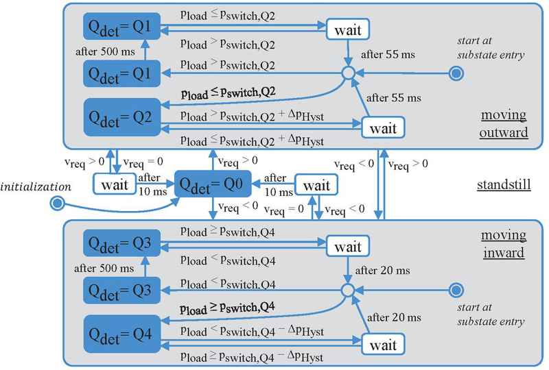
Figure 7 Quadrant detection.
On initialization of the control the detected quadrant is Q0. Based on the velocity request , one of the substates “moving outward” or “moving inward” is entered. They are left once the request changes direction or equals zero. Inside the substates the hysteresis boundaries for the load pressure are implemented. To further prevent unwanted quadrant switches because of short impulses, additional wait times are introduced before a quadrant is left. A longer wait time of 500 ms is added after entering each of the pumping modes to allow the initial excitation after valve actuation to subside and prevent a quadrant switch. Therefore, the states in which Q1 and Q3 are detected are duplicated. The times are chosen based on iterative testing and might not be optimal. It should be emphasized that a request to change velocity direction or to stop will still lead to a quick switch of quadrant.
In the following section, the EHA controller state machine – whose main function is the synchronization of the valve positions and motor speed – will be introduced. One example of the required synchronization is the start of pump rotation. Before a flow into the cylinder can be provided, the load-holding valve on the outflow cylinder side needs to be opened. However, there is a delay or dead time before a valve control signal change takes effect, which must be accounted for to achieve better system performance. The symbols used are explained in more detail in the nomenclature. They comprise the times needed to change valves states, the time delay of the motor , the current rotational speed of the hydraulic unit and of course the detected quadrant . The sequences are divided into Figure 8 and Figure 10 to keep them as organized as possible.
Figure 8 shows the sequences for acceleration and reversal of the cylinder velocity. The main quadrant states are visualized with blue boxes. As shown in Figure 7, the initially detected quadrant is defined as Q0 and the EHA controller state machine is therefore also initialized in Q0. Transition states are depicted in white boxes with blue borders and are grouped by a gray background based on their intended working conditions. For instance, the upper gray area contains states relevant to outward acceleration of the cylinder.
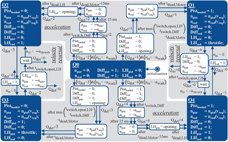
Figure 8 EHA controller – acceleration and reversal of cylinder movement.
Based on the detected quadrant , different sequences are necessary for acceleration, each represented by a blue arrow with a condition based on detected quadrant and current rotational speed of the pump.
If the external load is directed against the requested movement direction (Q1 & Q3), the load-holding valve blocking the outflow of the cylinder is first increasingly opened (mode denoted “opening”) and in case of Q3 the differential valve on the piston side is opened. After the maximum switching time minus the motor delay has elapsed, the motor signal is applied. Finally, after a wait time equal to the motor delay, the valve at the outlet is then switched to throttling mode. The valve is initially slowly opened to prevent hydraulic tensioning of the cylinder, before closing it again to achieve throttling.
If an assistive load acts on the cylinder, a quick opening of the loaded load-holding valve results in a strong acceleration due to the sudden drop of pressure in the cylinder chamber. Afterwards the flow rate surplus due to the higher cylinder velocity would result in a pressure spike at the motor inlet slowing the cylinder down again. This behavior was deemed undesirable and the displayed approach implemented. By briefly turning the hydraulic unit in the opposite direction the volume between the motor inlet and LH valve is pressurized. The approach can be refined further by adapting the time the pump runs depending on the pressure level. Additionally, the valve current is increased slowly (mode “opening”) to allow for smoother pressure equalization and acceleration of the cylinder. As soon as the valve should start to move according to the datasheet – after passed – the pump direction is changed back to the correct one.
After stopping the cylinder, which will be elaborated on later, the hydraulic unit may continue to spin. To prevent the start of the sequences with a high-speed rotation in the wrong direction, a check against a threshold is added.
The reversal of the cylinder movement under the same load direction can be handled well by the controller since it is primarily influenced by the rotational speed of the hydraulic unit. Especially when entering the motoring quadrants Q2 & Q4, precise synchronization is required to prevent the previously described pressure drop caused by the motor turning while the valve is still closed. The implemented approach is compatible with either faster valve or faster motor characteristics as displayed in Figure 9. By first dropping the requested motor signal down to the minimum rotational speed the rotational speed is reduced and a switch of rotational direction prevented. Only after the switching time of the valve has passed, the signal is changed to the value calculated based on the requested speed, ensuring an open valve and preventing a pressure drop due to insufficient flow out of the cylinder. Furthermore, the valve on the cylinder chamber with outgoing flow during pumping mode is only closed once the rotational speed drops below a threshold ensuring that the pump has switched rotational direction and preventing a blockage of cylinder outflow.
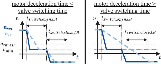
Figure 9 Motor speed request during movement reversal.
A trivial value for is zero, but a higher value, considering the required switching time, can increase performance by earlier actuation. A switch into the pumping quadrants requires less synchronization because throttling and therefore a certain amount of hydraulic tensioning is desired. Depending on valve and motor characteristics, a more detailed synchronization may be required as well.
In Figure 10 the sequences for a quadrant switch due to reversal of load direction and stopping are presented, which are complementary to the ones in Figure 8. In theory four exit paths for each quadrant exist since a switch from each quadrant to each other can occur. For Q1 to Q4 the switch to Q0 is combined with another switch, resulting in a total of three exit paths for the presented control approach.
Switches of load direction cannot be predicted and are critical since the loaded cylinder side switches, requiring an adaptation of pump speed. As explained previously, the time until a loss of control depends on the virtual boundary, the valve boundary and the throttle boundary. To allow for an adaptation of pump speed during the switches, the load-holding valves are switched to “resistance” mode first, in which the cylinder speed is valve controlled and the cylinder is decoupled from the hydraulic unit.
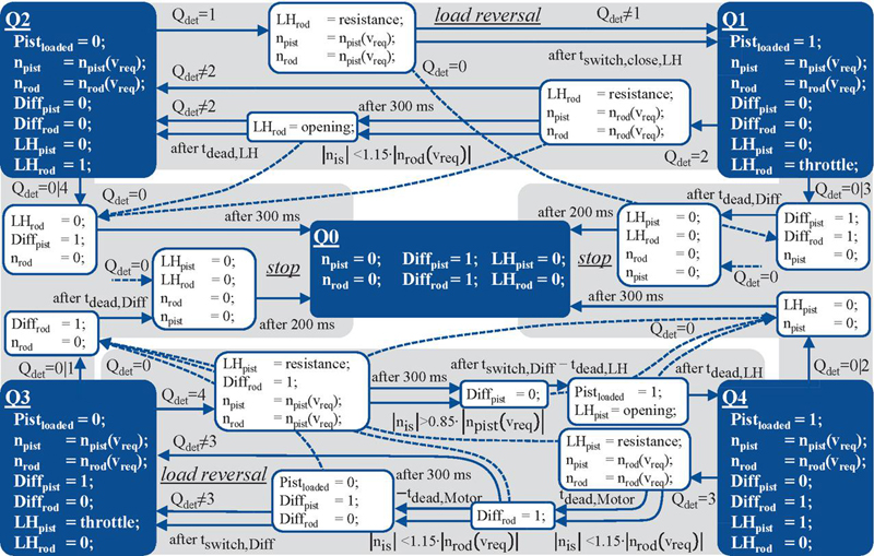
Figure 10 EHA controller – stopping and reversal of load direction.
If the system switches to a motoring quadrant, the valve slowly opens to allow for smooth pressure equalization. To prevent the cylinder from slowing down during the Q3Q4 transition, the differential valve on the piston side only closes if the difference between the current and requested pump speeds is less than 15%, or after 300 ms have elapsed. The same logic applies to the Q4Q3 switch, where the differential valve must open to prevent a reduction in rotational speed and slow the cylinder down. Switching from Q2 to Q1 only requires changing the mode of the load-holding valve on the rod side. The time required to increase the pump speed depends on motor performance and the current operating load, but it is usually brief. While the motor speed is smaller than the requested speed, the flow rate, and therefore the cylinder velocity, may be smaller as well.
The implemented approaches will not result in perfectly smooth cylinder velocity during switches. Instead, they aim to limit the intensity and duration of deviations as much as possible. Whether the remaining deviations can be accepted depends primarily on the operator’s subjective assessment. Based on experimental data and the rough operating conditions of excavators, the authors assumed that minor, brief deviations could be tolerated. However, this assumption must be verified through experimentation in the future, as no meaningful metric specific to mobile machinery was found.
The EHA is primarily stopped by closing the load-holding valves. During a pumping operation, both pump ports are connected by opening the differential valves. This results in rapid depressurization and cutoff of energy. An immediate stop of the EHA will result from a stopping signal during any sequence. The dashed arrows marked in Figure 8 are linked to the similarly marked arrows in Figure 10.
Switches between quadrants of the same kind (Q1Q3 & Q2Q4) are handled by first stopping and then accelerating again. An alternative solution that allows recuperation is possible by using the motor to slow down instead. Switches between Q1Q3 occur frequently when cylinder friction forces dominate.
4 Simulation
In this chapter, the simulation design is briefly explained as well as the testcases used. Afterwards, the simulation results are introduced and discussed.
4.1 Design
The simulation approach used in this study is described in more detail in [16]. The hydraulic circuit is modelled and parameterized in the lumped parameter fluid power simulation program DSHplus and exported as a Functional Mock-up unit (FMU). It is then imported into Matlab Simulink, where the control is implemented. The most important simulation parameters were selected for a 1,8-t excavator and are given in Table 1. The differential valves are modelled to have a linear opening characteristic and the load-holding valves are modelled as first-order lag elements. The sum of dead times and switching times is equal to the values taken from data sheets. Volumetric and hydromechanical efficiency of the pump are based on a measured characteristic field, while the cylinder friction is based on existing measurement data. The electric motor is of PMSM type and is modelled as shown in Figure 11. The model aims to include the reduction of torque at higher speeds. The maximum motor torque as function of the rotational speed is therefore taken from the data sheet of the motor. Depending on the difference between requested speed and current speed a PI-controller adjusts the applied motor torque . The acceleration is then calculated based on , the current motor load as result of pressure difference and the moment of rotational inertia of the motor and pump .
The simulation allows investigation of any combination of velocity and force. Starting, the focus is on the circuit behavior for the test cases displayed in Figure 12. The velocity reversal case is used to investigate the corresponding quadrant switches by applying a constant force and changing the requested velocity direction. Simulations were executed for all combinations of force and velocity as the velocity value correlates to the initially requested speed. During the force reversal test case, the velocity is kept constant and the applied force is changed linearly. correlates roughly to the position of the hysteresis band. Therefore, the positive value is used for negative velocities and vice versa. It was adjusted to achieve the desired quadrant switches due to the influence of friction. Simulations were conducted for each combination of velocity and change of force . The start position of the cylinder is set to 50 mm for positive velocities and 365 mm for negative velocities.
Table 1 Simulation parameters
| Name | Parameter | Value | |
| pump displacement volume | 5.4 | cm3 | |
| cylinder piston diameter | 60 | mm | |
| cylinder rod diameter | 35 | mm | |
| cylinder stroke | 415 | mm | |
| cylinder equivalent mass | 1000 | kg | |
| accumulator nominal volume | 2 | l | |
| accumulator pre-charge pressure | 4.5 | bar | |
| oil bulk modules at high pressures | 14,000 | bar | |
| dead time motor | 50 | ms | |
| dead time differential/load-holding valve | 20 | ms | |
| switching time differential valve | 40 | ms | |
| opening time load-holding valve | 50 | ms | |
| closing time load-holding valve | 150 | ms | |
| rotational acceleration limit | 25,200 | rpm/s | |
| moment of inertia of motor and pump | 0.011 | kgm2 | |
| boundary friction | 250 | N | |
| release point | 50 | mm/s | |
| viscous dampening | 10 | Ns/mm |
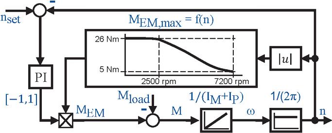
Figure 11 Simulation model of the PMSM.
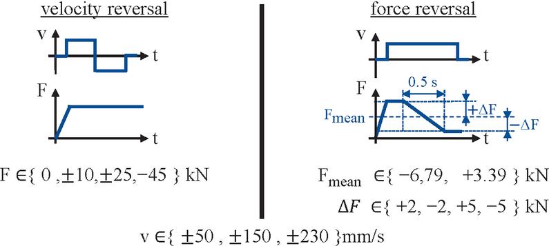
Figure 12 Test cases.
Additionally, a measured dig and dump cycle of an arm cylinder from a 1.8-t excavator was investigated. The velocity profile is derived from the cylinder position and the external force from the measured cylinder chamber pressures, which were all sampled with 100 Hz. The resulting profiles are first filtered with a low pass filter with passband frequency of 10 Hz and then are linearly scaled to fit the maximum operation conditions of the EHA. The maximum velocities are -250 mm/s and 230 mm/s and the maximum forces result from a maximum operation pressure of 180 bar to -33 kN and 51 kN. Therefore, scaling is only applied to the load forces to prevent overloading of the EHA and opening of the pressure relief valves. The maximum design pressure of the EHA is comparable to the one of the reference system. The higher measured forces are most likely dynamic system responses. Absolute velocities below 9 mm/s are set to zero to remove small movement requests resulting from filtering and are instead handled as full stop requests. The measured and processed profiles are shown in Figure 13.
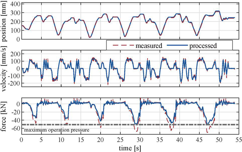
Figure 13 Dig and dump load cycle – measured and processed.
The top graph shows the measured and processed cylinder position. The latter is the result of integration of the processed velocity in addition to the starting position. Both correlate closely with each other.
In the next graph measured and filtered velocities are displayed. The effect of the filtering is clearly evident as the high frequency parts are filtered out. Additionally, the amplitude of short-term movements is reduced. Since the measurements are a result of the original valve-controlled system, it seems plausible to neglect these discrepancies. The change of the hydraulic system will inevitably change the system response.
Lastly, the measured and filtered forces as well as the force correlated to the designed maximum operation pressure are displayed. As intended the forces do not exceed the limit, preventing an unintended opening of the DBVs. The correlation between both profiles is still recognizable.
4.2 Results
In this section, the simulation results for the introduced test cases of velocity and force reversal as well as the dig and dump cycle are shown and discussed.
4.2.1 Velocity Reversal
Figure 14 shows the simulated cylinder velocities for the test case in which the direction of cylinder movement is reversed. Graphs 1, 3 and 5 (grey boxes with numbers) show the simulation results with a positive starting velocity and graphs 2, 4 and 6 the ones with a negative. The shown period excludes the initial load application. The requested velocity correlates with in Figure 6 and therefore the change rate is not limited.
As shown in Figure 1, a negative external force corresponds to a force trying to push the cylinder inward (Q1 & Q4). Looking at the velocities, the transitions from Q4Q1 and Q2Q3 are – except for smaller oscillations – smooth and linear as desired. The transitions Q1Q4 and Q3Q2 show the designed rest close to zero velocity as shown in Figure 9 before accelerating again, noticeable by the offset between the lines above and below zero velocity. The influence of the reduced torque of the electric motor is evident, resulting in speed deviations for higher loads as well as reduced acceleration.
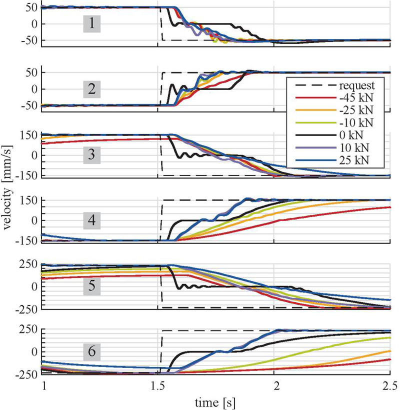
Figure 14 Results for the test case velocity reversal.
As previously explained, at low external load conditions, the friction forces dominate, resulting in a quadrant switch Q1Q3. Control-wise this is handled by a combination of stopping and accelerating, which clearly is evident for 0 kN (black lines). The velocity is reduced faster since stopping is achieved by closing the load-holding valves instead of slowing down the motor. To increase efficiency further, an additional sequence can be added that slows the cylinder down due to motor speed before then changing into the acceleration sequence.
Overall, the performance of the control is rated good. The transitions are smooth and there are only movements in the requested direction. The oscillations after stopping are a result of the quick deceleration. The small oscillations during acceleration are assessed to be not noticeable during operation, since the operation conditions of mobile machinery are rough.
4.2.2 Force reversal
Figure 15 shows, analogous to Figure 14, the simulated cylinder velocities for the different force combinations of the test case force reversal. The simulation results are categorized by the switch of operating quadrant, resulting in four groups. The time, when the quadrant switch is detected, is marked by a vertical line in the same color as the corresponding velocity plot.
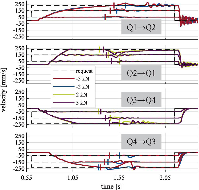
Figure 15 Results for the test case force reversal.
The topmost graph shows the switch Q1Q2. During the acceleration phase, small oscillations can be seen. Also, slower acceleration due to the reduced torque capacity of the electric motor at high speeds is evident as well. During the switch, the motor speed needs to decrease to adjust to the smaller flow rate because of the smaller cylinder rod area. Looking at the period in which the switch occurs, only small deviations are visible. The momentum of mass, assistive load and resistive valve mode keep the velocity close to the requested value. The initial overshoot at the higher load change rate is a result of the valve dynamics and the time needed to switch to resistive mode. The valve closes too slowly, so that the assistive load accelerates the cylinder. At lower change rates, the cylinder is still controlled by the pump speed if the rotational speed is reduced, resulting in a slowdown before valve control takes over. Looking at the requested velocities of 230 mm/s oscillations are clearly evident. The motor speed does not match when the differential valve closes and results in an excitation of the system.
The second graph displays the results for the switch Q2Q1, in which the pump speed needs to increase. After the quadrant switch is detected, the cylinder slows down due to friction and throttle pressure buildup. As soon as the pump flow rate matches the required cylinder flow rate, the pressure increases and the cylinder is controlled by the pump flow rate again. The switch back to pump control results in a small excitation. Higher change rates of load result in a faster slowdown. The pump speed adjusts fast enough to prevent large deviations at low speeds. At higher speeds, the reduced performance and larger speed adjustments increase the required period, resulting in larger deviations.
The switches from Q3Q4 are shown in the third graph. Analogue to Q2Q1, the pump speed needs to increase during the switch, but switches to motoring mode. At higher speeds, the pump speed does not match the required speed when the resistance mode is exited, resulting in a small excitation. The initial slowdown is a result of the pump rod side port being connected to the accumulator, removing the pushing force and the time required by the valve to switch to resistive mode. The valve dynamics also explain the small overshoot afterwards, since the assistive load continues to increase.
Lastly the switches from Q4Q3 are plotted in the downmost graph. Looking at the cylinder velocities, the worst performance of all quadrant switches is observed. While switches at slower speeds show only small deviations they increase with increasing speeds. Furthermore, a slower change rate of load initially results in acceleration due to a higher remaining load when the differential valve is opened. The valve must be opened, since otherwise the decrease of pump speed slows down the cylinder because of the reduced flow. At -150 mm/s and -230 mm/s and -5 kN load change rate the cylinder slows down as the valve boundary is reached – especially at -230 mm/s the pump speed adjustment is too slow.
Additionally, it can be observed that the valve-based stops result in strong oscillations after a movement in positive direction and a smooth deceleration after a movement in the negative direction. The reason for this is that the cylinder is under hydraulic tension while slowing down during retraction. In Q4 the pump provides more fluid to the rod side than is required by the slowing cylinder. This oversupply causes a pressure drop over the differential valve, tensioning the cylinder. The same is true for Q3 where the cylinder slows down faster than the pump because of the closing load-holding valve, resulting in hydraulic tension and preventing excitation of the system. In Q2 the pressure on the piston side of the cylinder is close to the accumulator pressure as the check valves are open. Only once the cylinder almost reaches zero velocity, the pump flow rate causes a small pressure buildup. The missing hydraulic tension results in a pressure buildup on the rod side due to the closing load-holding valve. The built-up pressure then accelerates the cylinder inward resulting in oscillations. The same occurs in Q1, but the pressure does not drop to the accumulator pressure and is higher afterwards due to the faster pump speed – smaller oscillations are the result.
The duration of the cylinder velocity deviations is short and small, except for the switch at higher speeds from Q4Q3. If it is considered that the reversal of external force presents a substantial change in operational conditions, a certain acceptance for deviations by the operator is likely. For example, a change from motoring to pumping occurs when ground excavation starts after lowering the arm in motor mode. Considering this, the velocity graphs shown are rated as acceptable. Nevertheless, as previously mentioned, further research and experiments with machine operators are necessary to confirm this assessment.
4.3 Dig and Dump Cycle
Following the simulation results of the processed dig and dump cycle, introduced in Figure 13, are shown and discussed. In favor of a higher level of detail only the first 13 seconds are shown. Figure 16 shows the simulation result for a control layout without an outer-loop position controller, where only feed forward control is established.
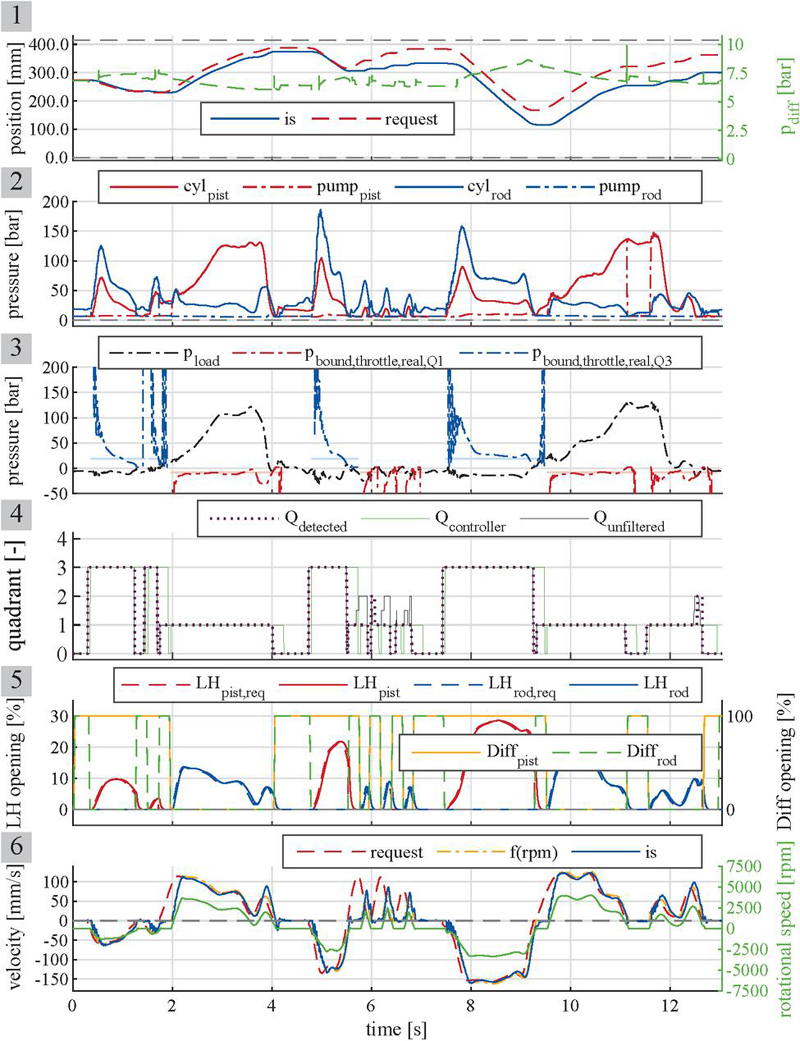
Figure 16 Simulation results of the investigated dig and dump cycle.
In the first graph the requested cylinder position, resulting from integration of the velocity request, in comparison to the simulated cylinder position are displayed. The initial cylinder start position is adjusted to prevent reaching the cylinder end stops. It can clearly be seen that over time deviation increases. Additionally, the pressure between accumulator and differential valves is plotted. This pressure is roughly equal to the accumulator pressure as both volumes are only separated by a check valve. The pressure drops during cylinder extension and rises during retraction. The pressure spikes shown are the result of the differential valves activation during pressurization of the corresponding pump outlet piping.
In the second graph the cylinder chamber and pump outlet pressures are shown. The resulting load pressure, calculated by Equation (1), is shown in the third graph. Also, the hysteresis bands are displayed as horizontal bars, which are colored in light red for Q1 and light blue for Q3. The current operating quadrant of the EHA controller is used for determination, which is shown in the fourth graph. As described previously, these bars represent the switching condition between quadrants and are based on a fixed pressure drop . The actual pressure drop depends on the current flow rate and valve opening, with the latter being influenced by actuation lag and valve dynamics. The real throttling boundary therefore is described by Equation (22) and Equation (23), considering the actual required pressure drop across the load-holding valve as given by Equation (24) and across the differential valve following Equation (25) (both based on Equation (13)). The flow rate over the differential valve in Q3 is the difference between cylinder and pump flow rate. These “real” boundaries are displayed in the third graph as well. Per design they should stay slightly below the horizontal bars in Q1 and slightly above the bars in Q3. At the beginning of a quadrant the real boundary is significantly higher than required and over time approaches and even dips below the designed boundary.
| (22) | |
| (23) | |
| (24) | |
| (25) |
The different definitions of current operational quadrant are depicted in graph four. The “unfiltered” quadrant is selected based on the velocity request and the current load pressure, using the boundaries defined by and . If the current operating conditions fall within the hysteresis band, the average of the two adjacent quadrants is used (1.5 or 3.5). Therefore, no filtering due to delay before a quadrant switch is applied. Additionally, the output of the quadrant detection and the current operation quadrant of the EHA controller is shown. As previously described, they differ from each other since the EHA controller quadrant refers to the controller’s current operational mode which can be different from the output of the quadrant detection. It is important to note that the EHA controller’s quadrant output only changes once a transition is complete, which explains the delay in reference to the detected quadrant. The detected quadrant for most parts shows no deviation and only truly short delay in relation to the unfiltered one. The main deviations arise during the succession of the three short outward movements around 6 seconds due to the minimum time required in Q1. The detected switch to Q2 at the end is not represented by the controller quadrant because the transition is cancelled before finishing due to a stop request.
On close inspection one can see that the EHA is only operational in Q1 and Q3. The reason for this might be the limited mass of the arm of the 1.8-t excavator in combination with the relatively high cylinder friction, preventing the recuperation of energy. In larger excavators the higher ratio between mass force and friction should however allow for recuperation.
The fifth graph depicts the simulated actual valve openings for the load-holding and differential valves. Additionally, the controller’s requested valve positions for the load-holding valves are shown. Upon closer inspection, the modeled delay between the requested and current positions can be seen. The faster the acceleration or deceleration, the greater the mismatch between the flow rate and the valve position. Due to time delays upon entering the quadrants, the acceleration is higher than requested. This results in a larger mismatch, a higher real boundary, and higher cylinder chamber pressures. During deceleration, the velocity gradient shows a smaller time delay and lower inclination. This results in smaller mismatches and better tracking of the desired boundary. Convergence of the real and theoretical boundaries results from a better match between the flow rate and valve opening during semi-stationary operation, as well as adjustment of the valve opening with the implemented PI controller to achieve the desired pressure drop. As previously described, the pressure drop is approximated by the difference between the cylinder chamber pressures and and the pressure at the leakage port of the pump .
Examining the real boundaries compared to the hysteresis bands (horizontal bars) in graph 3 they follow the designed value quite good. For Q1 operation (red) the dashed-dotted red line mostly lies below or close to the lower edge of the red bar whereas during Q3 operation (blue) the dashed-dotted line stays above or close to the upper edge of the blue bar. As reminder, firstly, if the load pressure goes over the edges of the bars long enough, a switch of operating quadrant is initiated. Secondly, the pressure boundary was derived as the condition where pump control is lost and a switch to valve control occurs. Therefore, the lines ideally should not touch the bars. However, small overlaps will only result in a slight increase in outflow through the valve. The increase in cylinder speed requires higher pressure on the outflow cylinder chamber side due to valve resistance and additionally reduces the pressure on the inflow side as soon as the check valves open to prevent cavitation. The influence on load pressure thereby is two-fold and a quadrant change more likely. Nevertheless, the available action time will be shortened due to a smaller or no gap between hysteresis band and throttle boundary.
Graph six shows the requested and actual cylinder velocity, as well as the cylinder velocity based on pump speed, neglecting volumetric efficiency (denoted f(rpm)). Due to delays between the requested cylinder movement and the start of pump rotation based on the developed control scheme, the requested velocity and the velocity based on pump speed differ. Close tracking of the requested velocity is observed once the initial delay and acceleration phase are over.
This is also reflected in the root mean square error (RMSE) as shown in Figure 17 for the entire cycle. As expected, the RMSE between the current and requested cylinder velocities is high after the initial movement request due to the delayed pump start. Consistent with this, the RMSE between the current cylinder velocity and the velocity based on pump speed is smaller. Additionally, the integral of the time-multiplied absolute value of the error (ITAE) is given for both differences. As expected, the ITAE between the requested and actual velocities is higher, it especially increases during initial delays when the RMSE is high.
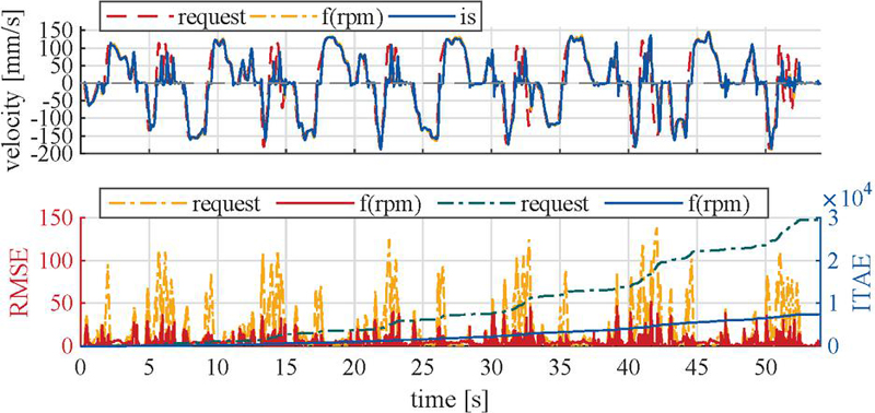
Figure 17 RMSE and ITAE of cylinder velocity (requested and based on pump speed).
The RMSE and ITAE are also given for the cylinder position compared to the requested cylinder position in Figure 18. Due to difference in requested and actual velocity in combination with no position feedback, both signals are drifting apart as expected, resulting in a higher deviation over time. The maximum RMSE is 163 at 41 seconds. Especially during the initial acceleration the deviation increases due to the delayed start of cylinder movement. The offset between both signals results in a continuous rapid ITAE increase.
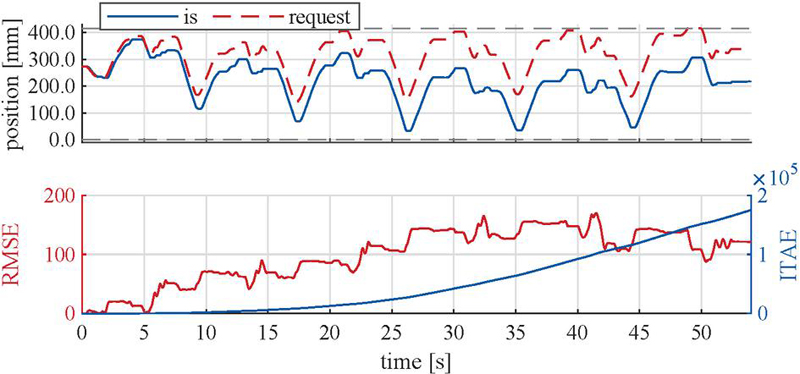
Figure 18 RMSE and ITAE of cylinder position (without position controller).
While mobile machinery is often designed as open feed-forward control topology, the operator closes the control loop by adjusting his input based on his visual perception. To represent this behavior or as a basic closed outer-control scheme, a P-controller is added that adjusts the velocity request during movement based on the deviation between requested and actual cylinder position. The controller does not alter the periods in which the cylinder moves. The simulation results of requested and actual position as well as RMSE and ITAE are given in Figure 19.
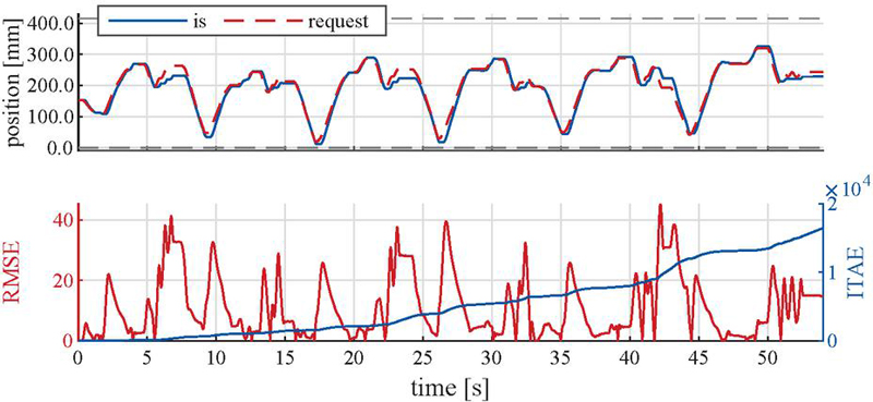
Figure 19 RMSE and ITAE of cylinder position (with position controller).
By comparison with Figure 18 it is clearly evident that even this basic controller setup improves position tracking by compensating for delays. The ITAE is about one-tenth that of the setup without a controller. The highest remaining RMSE of 42 mm is only about 26% of the maximum without a P-controller. It occurs between 40 and 45 seconds, when the cylinder moves outward and inward quickly in succession. This is because the influence of the initial delay cannot be compensated for during the short movements. The same behavior occurs between seconds 5 and 7 when three short movements occur, and the influence of the delay accumulates. Typically, the operator would wait longer before reducing the velocity again to reach the desired position. Representing this behavior would require a complex control setup based on position instead of velocity with variable movement duration. This would alter the load cycle duration. While this approach is outside the scope of this paper, it can easily be concluded that it would further improve tracking performance during a succession of short movements.
The requested cylinder velocity is tracked closely with exception of phases with inherent delay. The delay between request and start of motion in Q1, Q2, Q3 and Q4 is about 100 ms. The longest delay of about 270 ms occurs during Q1Q3, because of the two-step sequence, consisting of a full stop and acceleration. The delay mainly consists of a wait time of 200 ms to ensure full closure of the load-holding valves. As mentioned previously, an optimized sequence can be introduced to specifically manage the switches Q1Q3, which uses recuperation to slow down the cylinder and may also reduce the delay between motions.
As previously mentioned, the authors could not find any publications related to specific metrics or key values for assessing operator acceptance of mobile machine controls. A review of research related to the impact of network latency on a wide range of teleoperation applications is presented in [21]. They conclude that a latency of less than 250 ms or 300 ms is acceptable and one of less than 170 ms is preferable for connected and autonomous vehicles. The time between action input and output should be in the range of 20 ms to 80 ms. Using this as reference, while a comparison might not be fully suitable, the delays of the EHA are in an acceptable range. During operation in a quadrant the EHA’s delay is mostly related to the lag of the motor, which is in the range of 50 ms. Based on the thresholds mentioned this should not influence operator acceptance. Only the 270 ms lag during the switch Q1Q3 could have negative impact but should still be within an acceptable range.
5 Conclusion
In this paper, a hydraulic circuit for an electro-hydrostatic actuator (EHA) aimed at the application in mobile machinery was investigated. The circuit was selected based on cost considerations, the use of a high-speed internal gear pump and standard differential cylinder, inclusion of load-holding capability and wide flexibility of the control. The existing operation boundaries of the circuit require an expansion of the pumping quadrant to allow full coverage of the four-quadrant plane, which is achieved by active throttling of the outgoing cylinder volume flow using proportional load-holding valves. A virtual boundary for the quadrant switch is defined based on the derived physical boundaries and combined with active hysteresis to prevent unwanted quadrant switches. The presented controller aims to synchronize motor speed with valve positioning, allowing for smooth cylinder velocities under changing velocity requests and load directions.
The simulation results aim to demonstrate the functionality of the EHA and the corresponding control approach under changing excavator working conditions. Therefore, they are interpreted qualitatively rather than quantitatively. The results show excellent performance for velocity reversal under constant force, which only very brief and short velocity deviations. During the reversal of external load under constant speed, the deviations are higher but again rated as acceptable for the application in an excavator. The biggest observed deviations result from switches Q4Q3, where especially high speeds show larger deviations because of the required adjustment of pump speed combined with reduced torque capacity of the electric motor. Lastly, the cylinder position tracking during a measured dig and dump cycle is also rated as good once a simple P-controller is used as substitute for the machine operator. Without this adjustment, the requested and actual cylinder position drift apart due to incorporated delays in the control scheme. By incorporating this controller, the ITAE can be reduced by a factor of ten and the maximum RMSE from 163 mm to 42 mm, representing an improvement of 74%.
The results are overall promising and encourage further investigation, especially experimental validation.
6 Outlook
Experimental validation using an excavator with a machine operator is recommended and planned. Therefore, a demonstrator of the EHA will be built and used to validate the simulation results experimentally.
In future, the control scheme can be further refined and optimized. A general fine tuning of the control parameters, like adjusting the waiting times or changing the placement and width of the hysteresis band, may improve performance. Even more sophisticated sequences can improve performance further. For example, an optimized pre-pressurization during the acceleration sequence in motor operation or a sequence allowing for recuperation during switches between quadrants Q1 and Q3 can be implemented. Former decreases excitation due to non-matching pressure levels when the load-holding valves open, latter increases efficiency by recuperating kinetic energy stored in the moving masses instead of throttling it but increases the required time for the direction switch.
Acknowledgement
The IGF research project “22246 N/1” of the research association Forschungskuratorium Maschinenbau e. V. – FKM, Lyoner Straße 18, 60528 Frankfurt am Main was supported from the budget of the Federal Ministry of Economic Affairs and Climate Action through the DLR within the scope of a program to support industrial community research and development (IGF) based on a decision of the German Bundestag.

Nomenclature
| Designation | Denotation | Unit |
| Cylinder areas | ||
| Actuation of the switching valves | – | |
| External cylinder force | ||
| Friction force | ||
| Metering coefficient of the differential valve | ||
| Metering coefficient of the load-holding valve depending on spool position | ||
| Mode of the load-holding valves | – | |
| Equivalent mass | ||
| Current rotational speed of the motor | ||
| Minimal rotational speed of the pump | ||
| rotational speed calculated by EHA controller if piston/rod side is loaded | ||
| Threshold during a change of rotational direction | ||
| Accumulator pressure | ||
| Load pressure boundary introduced by the accumulator pressure | ||
| Load pressure boundary resulting from the cylinder friction | ||
| Load pressure boundary resulting from ideal throttling with | ||
| Load pressure boundary resulting based on current flow rate and valve position | ||
| Load pressure boundary introduced by the load-holding valve | ||
| Pressure at the leakage port of the pump, connected to the differential valves | ||
| Load pressure | ||
| Cylinder pressures | ||
| Virtual boundary of at which the quadrant switch is initiated | ||
| Pressures at the pump ports | ||
| Equal to 1, if piston side is loaded | – | |
| POCV | Pilot-operated check valve | – |
| Actual required pressure drop over the differential valve to allow the current cylinder flow rate through the valve | ||
| Width of hysteresis | ||
| Actual required pressure drop over the load-holding valve to allow the current cylinder flow rate through the valve | ||
| Pressure difference while throttling | ||
| Flow rate | ||
| Operating quadrant in the four quadrant plane (Q0 = standstill) | – | |
| Output of quadrant detection | – | |
| Dead time of load-holding valve | ||
| Dead time of switching valve | ||
| Dead time of motor | ||
| Time to open/close the load-holding valve (incl. dead time) | ||
| Time to switch the position of the switching valve (incl. dead time) | ||
| Requested cylinder velocity | ||
| Cylinder velocity | ||
| Cylinder area ratio | – |
References
[1] Pietrzyk, T., et al., Entwicklung und Auslegung einer elektro-hydraulischen Achse mit einem 48 V High-Speed-Antrieb zur Dezentralisierung der Arbeitshydraulik eines Kompaktbaggers. Proc. of Hybride und energieeffiziente Antriebe für mobile Arbeitsmaschinen 7. Fachtagung, 20. Februar 2019, Karlsruhe.
[2] Pietrzyk, T. and Schmitz, K., Messtechnische Erprobung einer elektro-hydraulischen Linearachse mit High-Speed Antrieb. Proc. of Hybride und energieeffiziente Antriebe für mobile Arbeitsmaschinen 8. Fachtagung, 23. Februar 2021, Karlsruhe.
[3] Pietrzyk, T., Roth, D., Jacobs, G., and Katharina, S., Design of a High Speed Internal Gear Pump to Increase the Power Density of Electro Hydraulic Actuators (EHA) in Mobile Applications. Proc. of Volume 7: Fluids Engineering. Salt Lake City, Utah, USA, 11.11.2019 – 14.11.2019, 2019. DOI:10.1115/IMECE2019-10351.
[4] Pietrzyk, T., Entwicklung einer Hochdrehzahl-Innenzahnradpumpe für die Elektrifizierung mobiler Anwendungen am Beispiel einer autarken dezentralen elektro-hydraulischen Achse, RWTH Aachen University, 2022. DOI:10.18154/RWTH-2022-00767.
[5] Pietrzyk, T., Roth, D., Schmitz, K., and Jacobs, G., Design study of a high speed power unit for electro hydraulic actuators (EHA) in mobile applications. Proc. of 11th International Fluid Power Conference, 2018. DOI:10.18154/RWTH-2018-224632.
[6] Williamson, C. and Ivantysynova, M., Stability and motion control of inertial loads with displacement controlled hydraulic actuators. Proc. of 6th FPNI-PhD Symp. West Lafayette, Indiana, June 15–19, 2010, S. 499–514.
[7] Michel, S., Elektrisch-hydrostatische Kompaktantriebe mit Differentialzylinder für die industrielle Anwendung, Dissertation, TU Dresden, Dresden, 2020. DOI:10.25368/2021.86.
[8] Williamson, C. and Ivantysynova, M., Pump mode prediction for four-quadrant velocity control of valveless hydraulic actuators. Proc. of 7th JFPS International Symposium on Fluid Power. Toyama, Japan, 15–18 September, 2008.
[9] Wang, L., Book, W. J., and Huggins, J. D., A Hydraulic Circuit for Single Rod Cylinders. In: Journal of Dynamic Systems, Measurement, and Control, Vol. 134, No. 1, 2012. DOI:10.1115/1.4004777.
[10] Çalışkan, H., Balkan, T., and Platin, B. E., A Complete Analysis and a Novel Solution for Instability in Pump Controlled Asymmetric Actuators. In: Journal of Dynamic Systems, Measurement, and Control, Vol. 137, No. 9, 2015. DOI:10.1115/1.4030544.
[11] Imam, A., Rafiq, M., Jalayeri, E., and Sepehri, N., Design, Implementation and Evaluation of a Pump-Controlled Circuit for Single Rod Actuators. In: Actuators, Vol. 6, No. 1, S. 10, 2017. DOI:10.3390/act6010010.
[12] Imam, A., Tolba, M. S., and Sepehri, N., Improving performance of pump-controlled hydraulic circuits for single-rod actuators: conceptual study. In: Journal of Physics: Conference Series, Vol. 2616, No. 1, S. 12015, 2023. DOI:10.1088/1742-6596/2616/1/012015.
[13] Koury Costa, G. and Sepehri, N., A Critical Analysis of Valve-Compensated Hydrostatic Actuators: Qualitative Investigation. In: Actuators, Vol. 8, No. 3, S. 59, 2019. DOI:10.3390/act8030059.
[14] Gøytil, P. H., Padovani, D., and Hansen, M. R., A Novel Solution for the Elimination of Mode Switching in Pump-Controlled Single-Rod Cylinders. In: Actuators, Vol. 9, No. 1, S. 20, 2020. DOI:10.3390/act9010020.
[15] Kärnell, S. and Ericson, L., Hysteresis Control in Pump-Controlled Systems—A Way to Reduce Mode-Switch Oscillations in Closed and Open Circuits. In: Energies, Vol. 15, No. 2, S. 424, 2022. DOI :10.3390/en15020424.
[16] Figge, F. and Schmitz, K., Simulative Comparison Approach of Electro-Hydrostatic Actuator Circuits in Excavators. Proc. of ASME/BATH 2023 Symposium on Fluid Power and Motion Control. Sarasota, Florida, USA, 16–18. October, 2023. DOI:10.1115/FPMC2023-111798.
[17] Rahmfeld, R., Energy saving hydraulic actuators for mobile machines. Proc. of 1st Bratislavian Fluid Power Symposium. Casta-Pila, Slovakia, 2–3 June, 1998.
[18] Padovani, D., Ketelsen, S., Hagen, D., and Schmidt, L., A Self-Contained Electro-Hydraulic Cylinder with Passive Load-Holding Capability. In: Energies, Vol. 12, No. 292, 2019. DOI:10.3390/en12020292.
[19] Habibi, S. and Goldenberg, A., Design of a New High-Performance Electro-Hydraulic Actuator. In: IEEE/ASME Transactions on Mechatronics, Vol. 5, No. 2, 2000.
[20] Michel, S. and Weber, J., Energy-efficient electrohydraulic compact drives for low power applications. Proc. of Fluid Power and Motion Control FPMC 2012. Bath, United Kingdom, 12–14 September, 2012.
[21] Kamtam, S. Bhanu, et al., Network Latency in Teleoperation of Connected and Autonomous Vehicles: A Review of Trends, Challenges, and Mitigation Strategies. In: Sensors (Basel, Switzerland), Vol. 24, No. 12, 2024. DOI:10.3390/s24123957.
Biographies

Felix Figge received the bachelor’s degree in mechanical engineering with a specialization in design methodology in 2019 and the master’s degree in mechanical engineering with a specialization in product development in 2021, both from RWTH Aachen University. He is currently working as a Research Associate at the Institute for Fluid Power Drives and Systems (ifas), RWTH Aachen University. His research covers Fluid Power Systems in general but focuses on the development of an electro-hydrostatic actuator for application in mobile machinery.

Katharina Schmitz studied mechanical and chemical engineering at RWTH Aachen University and Carnegie Mellon University, Pittsburgh (USA) and graduated in 2015 as Dr.-Ing. at RWTH Aachen University. Since 2018, she is full professor at RWTH Aachen University and director of the Institute for Fluid Power Drives and Systems (ifas). In addition, she is Vice Dean of the Faculty for Mechanical Engineering at RWTH Aachen, a position she holds since 2020. Prof. Schmitz’s awards and honors include several best paper awards and 2023 IMechE Joseph Bramah Medal award.
International Journal of Fluid Power, Vol. 27_1, 85–126
doi: 10.13052/ijfp1439-9776.2714
© 2026 River Publishers