Mechanism and Performance Analysis of the Pilot-Pressure Control Two-Stage Valve Distribution High Pressure Radial Piston Hydraulic Motor
Tong Guo1, 2,*, Fumin Que1, 2, Xinming Li1, 2, Hao Liu3 and Tianliang Lin1, 2
1Huaqiao University, Xiamen, Fujian, China
2Fujian Key Laboratory of Green Intelligent Drive and Transmission for Mobile Machinery, Xiamen, Fujian, China
3Beijing Tianma Intelligent Control Technology Co., Ltd., Beijing, 100176, China
E-mail: guot@hqu.edu.cn
*Corresponding Author
Received 12 November 2025; Accepted 18 March 2026
Abstract
Radial piston motors are typical high-torque rotary actuators with good low-speed stability, high power density and cost efficiency, which are widely used in the field of heavy-duty machinery. The rated pressure of mainstream radial piston motors does not exceed 25 MPa due to the inherent limitations of their conventional flow distribution mechanisms. To address this issue, a new distribution scheme of pilot-pressure control two-stage flow distribution is proposed, in which the pilot-stage valve plate controls conical valve pairs serving as the main-stage distributors of the motor. Specifically, the study focuses on the mechanical principle and hydraulic performance of the pilot-pressure control flow distribution system, systematically analyzing the influence of two different configurations on motor output characteristics and further confirming the feasibility through simulation and experimental validation. This approach leverages the pilot ratio of the distribution valve to significantly reduce the pressure acting on the distribution pair, thereby achieving a substantial improvement in volumetric efficiency under high-pressure conditions and providing both theoretical innovation and practical engineering reference for the development of high-performance hydraulic motors.
Keywords: Hydraulic motor, pilot-pressure control two-stage flow distribution, radial piston, volumetric efficiency, valve distribution.
1 Introduction
Radial piston hydraulic motors, as conventional high-torque hydraulic motors with good low-speed stability, large displacement, high power density, etc., are widely used in high-power machinery and equipment fields [1–3]. The development of radial piston hydraulic motors primarily focuses on achieving higher pressure ratings to expand operational envelopes and enhance output performance [4]. However, the rated pressure of mainstream radial piston hydraulic motors is still difficult to exceed 25 MPa [5–7], which is lower than the working pressure achievable by pumps and axial piston motors. One of the main reasons is that the volumetric efficiency of radial piston motors is constrained by the sealing performance of the flow distribution mechanism under high working pressure [8–10].
As shown in Figure 1, most mainstream commercial radial piston motors adopt shaft distribution and valve plate distribution structures. Inevitably, floating gaps exist in the distribution pair, making it difficult to strike a balance between reducing leakage and improving transmission efficiency in the design of the distribution pair [11]. For shaft distribution and valve plate distribution, excessively small flow distribution clearance increases braking resistance on the main shaft, while larger clearances under high pressure lead to elevated leakage and degraded sealing performance of the motor. To overcome the limitations of the traditional direct flow distribution method, engineers have developed two-stage distribution approaches such as mechanical linkage and electro-hydraulic pilot control [12–16]. However, the former introduces intermediate transmission mechanisms that restrict the optimal operating range and require additional lubrication measures, while the latter suffers from high cost and complex drive systems caused by the electronic control components, making it unsuitable for direct substitution in existing application scenarios [17].
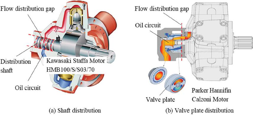
Figure 1 Distribution gap of conventional radial piston motor [5, 6].
Scholars have carried out research on the flow distribution pairs of high-power piston hydraulic devices. Wenqiang Shen et al. proposed a new type of low-speed high-torque hydraulic motor structure, which can effectively avoid the high- and low-pressure fluid communication leading to motor leakage [18]. Nan Xu et al. carried out a study on the influence of the structural parameters of spherical flow distribution plate on the flow and pressure characteristics of the motor piston chamber [19]. Yuan Chen et al. investigated the optimal microstructure of the piston pump cavity and the surface of the flow distribution plate when the efficiency loss is minimized [20]. Lokesh Kumar, Nimai Pada Mandal et al. investigated the pressure fluctuation, flow rate fluctuation, and the volumetric efficiency of the structure near the flow distribution plate of a piston pump under different pressures and flow passage angle [21]. Ganesh Kumar Seeniraj et al. established a simulation model of the flow distribution plate and analyzed the effects of its structural design on the flow fluctuation, fluid oscillating force and volumetric efficiency of the motor [22]. David Richardson et al. established a flow distribution plate motion model and analyzed the oil film thickness and motion pattern of the distribution pair under different states [23]. Dianrong Gao et al. conducted friction and wear studies on the distribution plate, machining special shapes on its surface to enhance its load-bearing capacity [24, 25]. Songlin Nie et al. proposed a new type of eccentric structure of the flow distribution plate, and the simulation results of the flow field model showed the feasibility of this structure [26]. Bergada et al. analyzed the motion law curve of the piston pump flow distribution pair gap with the rotation of the cylinder block [27].
In 2021, we proposed a motor employing pilot-pressure control dual pilot-operated check valves for flow distribution, utilizing the valve’s pilot ratio to reduce pressure on the distribution pair and minimize leakage [28]. However, due to the inherent spool response delay, cross-port flow occurs during piston port switching between the dual valves, exacerbating leakage losses [29–31]. To address the aforementioned issues and break through the 25 MPa pressure limit of mainstream radial piston motors, this paper proposes a novel pilot-pressure control two-stage flow distribution method, where a two-position three-way directional control valve governs the main-stage motor distribution. The system simultaneously reduces distribution interface pressure and enhances sealing dynamics during valve actuation, enabling the motor to maintain high volumetric efficiency at high working pressures.
2 Hydraulic Principle and Theoretical Analysis of the Motor
2.1 Flow Distribution Principle and Structure of the Motor
Figures 2(a) [32] and 2(b) respectively show the hydraulic schematic of the radial piston device with pilot-operated check valve and two-position three-way valve. The operating principle of the pilot-pressure control two-stage flow distribution is as follows: the suction and discharge actions corresponding to a single piston chamber are distributed by flow distribution valves, and the opening and closing timing of the seat valves is regulated by the pilot-stage. The pilot-stage is driven by the rotating shaft to switch communications between the control oil passages and the high- and low-pressure oil ports on the distribution shaft or distribution plate. These control oil passages are connected to the control chambers of the main valves to regulate the opening and closing of the inlet and outlet valves, enabling the intake or discharge actions of a single piston chamber. Figure 2(a) employs dual pilot-operated check valves for motor flow distribution, requiring each piston chamber to alternately connect to the inlet and outlet valves. The inherent spool response delay during valve actuation creates momentary cross-connection between both valves, intensifying internal leakage. To enhance sealing performance of the motor, this paper designs a pilot-pressure control two-position three-way directional valve scheme as shown in Figure 2(b), in which a single valve controls individual chamber flow distribution via pilot-pressure, reducing both valve count and structural complexity. The spool’s unique damping interface design significantly improves sealing performance of the valve during transitions between high-pressure and low-pressure.
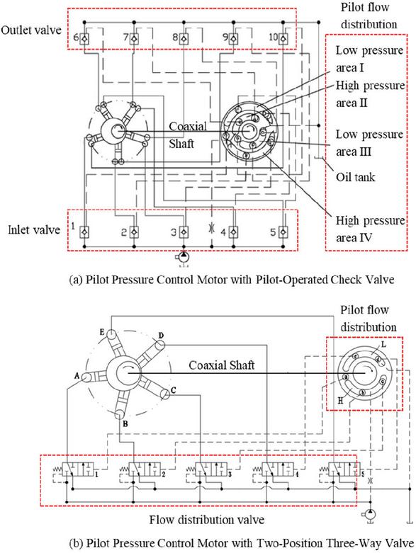
Figure 2 Pilot-stage flow distribution hydraulic schematics with different configurations.
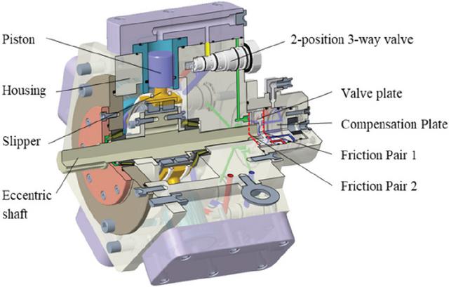
Figure 3 Motor three-dimensional structure.
The motor shown in Figure 3 is one of the engineering implementations of the hydraulic schematic diagram with two-position three-way valve, with its structure consisting of the housing, eccentric shaft, flow distribution valve plate, compensation plate, pistons, two-position three-way valve, etc. The performance of flow distribution valve critically impacts motor operation, as its structure illustrated in Figure 4. The spool moves under the pressure differential between the hydraulic control chamber and main-stage port, alternately connecting pressure port to actuator port or tank port to actuator port. And a damping orifice mating structure is designed for the transitional state before the valve seat fully closes, in order to reduce cross-flow among the three hydraulic ports and to minimize flow shock and internal leakage.
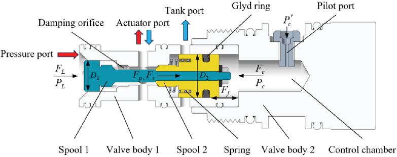
Figure 4 Three-dimensional structure of the two-position three-way valve.
2.2 Pressure–Flow Analysis of Flow Distribution Valves
To study the parameters affecting the response of the distribution valve and to analyze its opening and closing characteristics, it is necessary to conduct a pressure – flow analysis based on the valve structure and its operating principle, as shown in Figure 4. The fluid enters the control chamber of the distribution valve through a pilot port, which also functions as a damping orifice. When the piston chamber is in the filling stage, the fluid in the control chamber of the valve must have sufficient pressure to overcome the load pressure, spring preload, and frictional force, thereby pushing the spool to open the pressure port. Conversely, when the piston chamber is in the discharging stage, the load pressure and spring force work together to overcome the frictional resistance so as to open the tank port.
According to the above analysis, we can formulate:
| (1) |
– Pressure inside the hydraulic control chamber;
– Load pressure of the pressure port;
– Spring force;
– Spring preload force;
– Spool friction force;
– Diameter of the spool 1 adjacent to the pressure port;
– Diameter of the spool 2 adjacent to the control chamber;
– Spool mass;
– Spool acceleration.
When the two-position three-way directional valve operates under high working pressure, the spring force, preload force, and spool friction can be neglected. According to the orifice flow theory and Bernoulli’s principle, the fluid resistance acting on the spool is proportional to the square of its velocity, manifesting as a non-linear damping effect. At the very inception of movement, since the spool velocity is zero, the throttling resistance is also zero, and the high-pressure driving force indeed induces high acceleration. However, owing to the minimal mass of the spool, this initial acceleration causes the velocity – and consequently the non-linear fluid resistance – to surge rapidly until a dynamic balance with the driving force is achieved within an extremely short duration. Therefore, the transient phase dominated by the inertial term accounts for a negligible portion of the entire switching cycle, and the right-hand term of Equation (1) is thus approximated as zero.
According to the flow formula for thin-wall throttling orifices, the inflow rate into the control chamber and outflow rate from the control chamber can be calculated as:
| (2) | |
| (3) |
– Pilot pressure at the inlet of the pilot port;
– Flow coefficient of thin-wall orifice, generally taken as 0.6;
– Orifice area of the flow restrictor;
– Fluid density.
Therefore, the spool velocities in the filling and discharging stages of the piston chamber, denoted as and , are respectively:
| (4) | |
| (5) |
– Leakage flow rate in the pilot control chamber.
Substituting the designed system structural parameters into the above equation yields a spool response velocity of approximately 0.5 –1 m/s. Based on the spool stroke, the corresponding response time is at most 20 ms, which satisfies the flow-distribution requirements of the motor under low-speed, high-torque operating conditions.
The structure formed between the spool and the damping orifice can be modeled as an annular gap. In addition to axial flow caused by pressure difference, the flow is also influenced by shear forces due to the sliding of the spool surface. Since the diameter ratio of the spool damping section to the orifice is greater than 0.5, the influence of eccentricity can be neglected. Assuming laminar flow conditions around the spool, the leakage flows between the pressure port and the tank port corresponding to the piston chamber filling and discharging states, denoted as and respectively, are given as:
| (6) | |
| (7) |
– Diameter of the spool damping section;
– Radial single side clearance between spool and damping orifice;
– Dynamic viscosity of the fluid;
– Flow path length between spool and damping orifice.
When the two-position three-way directional valve has no damping orifice, direct-through leakage occurs during the spool switching process. The corresponding flow rate can be calculated using the Hagen–Poiseuille law. Accordingly, the leakage ratio between the configurations with and without a damping orifice is given as:
| (8) |
– Pressure difference between the two ends of the valve spool;
– Diameter of the motor oil passage;
– Length of the motor oil passage.
Substituting the previously derived formulas and the motor structural parameters into the above equation, and applying order-of-magnitude analysis, it is found that . Since the distribution valve structural parameters of the pilot-operated check valve motor and the two-position three-way valve motor are of the same order of magnitude, it can be concluded that the two-position three-way directional valve can effectively suppress the direct-through leakage occurring during the switching of the dual pilot-operated check valve.
3 Motor Simulation and Experimental Study
3.1 Simulation of the Motor Hydraulic System and Discussion of Results
To investigate the feasibility of using pilot valves for motor flow distribution, a hydraulic motor system was constructed in the AMESim simulation platform using components from the Hydraulic Component Design library, as shown in Figure 5(a). The single-piston super-component was configured in two different ways: one employing pilot-operated check valves (P. motor), and the other using a two-position three-way directional valve (T. motor), as illustrated in Figure 5(b) and Figure 5(c), respectively.
Taking the T. motor as an example, in Figure 5(c), the two-position three-way valve is responsible for distributing flow to the piston chamber, with its switching state controlled by the pilot timing control module. The piston’s displacement signal is captured by the piston motion function module and converted into an angular signal, which in turn influences the pilot-pressure output of the pilot timing control module, thereby triggering the next flow distribution event. This forms a closed-loop control system. A unilateral clearance of 0.1 mm was set for the damping orifice, and the valve’s opening and closing behavior during switching was simulated using the damping orifice timing control module. The pilot and main flow circuits of the motor are independently supplied by separate hydraulic pumps. Five such piston components are connected in parallel and linked to a torque motor assembly.
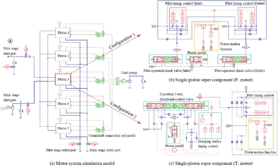
Figure 5 System simulation model and sub-model configuration.
To assess the output performance of the motor employing two different valve configurations under the same operating conditions, especially in terms of volumetric efficiency, it was assumed that the main friction pairs, including the piston pair and the distribution pair, were fully lubricated by oil films. Consequently, only small viscous friction losses were considered, and their effect on the output torque was neglected. The key system parameters were defined as shown in Table 1.
Table 1 Key parameters of the simulation
| Parameters | Value | Unit |
| Pilot-stage Inlet Flow | 5 | L/min |
| Main-stage Inlet Flow | 40 | L/min |
| Pilot-stage pressure | 10 | MPa |
| Tested Motor Displacement | 270 | mL/r |
| Counter-torque Motor Displacement | 450 | mL/r |
| Piston Pairs Clearance | 0.01 | mm |
| Distribution Pairs Clearance | 0.01 | mm |
As shown in Figure 6, both the output torque and rotational speed of the motor increase continuously after the system flow is introduced. Once stabilized, the torque fluctuates within a narrow range around a fixed threshold, with values remaining close for both configurations. The torque and speed response clearly indicates that the motor using the two-position three-way valve reaches a steady state faster than the one using pilot-operated check valves and exhibits a slightly higher final rotational speed, which can be attributed to the superior sealing performance of its distribution valve during switching, as discussed earlier. The output performance curves of the motor align well with expectations, thereby validating the feasibility of the pilot-based two-stage control flow distribution strategy.
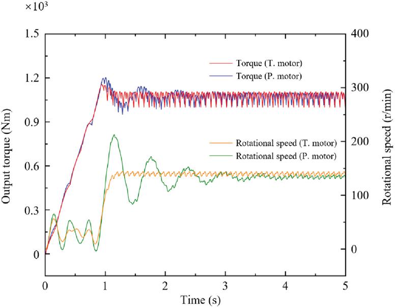
Figure 6 Output torque and rotational speed of the motor.
Figure 7 illustrates the main-stage flow rate and pressure of the motor system. Both motor configurations exhibit flow surges, with more pronounced surges occurring during the piston’s discharge phase. This is attributed to the higher-pressure differential across the valve spool during oil discharge compared to intake. The motor employing the two-position three-way directional valve demonstrates a significantly reduced peak flow surge, especially during the intake phase, where the surge becomes almost negligible. Under these conditions, the motor system is able to maintain a higher outlet pressure – reaching approximately 28 MPa – with reduced pulsation.
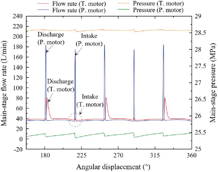
Figure 7 Flow rate surges and pressure pulsations of the main-stage.
The flow distribution process within the piston chamber is governed by the response of the pilot valve. Taking the motor equipped with a two-position three-way directional valve as an example, Figure 8 illustrates the corresponding piston chamber pressure, flow rate, and displacement curves under different valve openings. When the inlet valve spool opens, the piston chamber is positioned at its top dead center and begins the intake phase, during which the main flow enters the chamber and drives the piston downward until it reaches the bottom dead center. After half a revolution of the main shaft, the pilot control plate switches the pilot chamber from high-pressure to low-pressure oil, thereby triggering the opening of the outlet valve spool and enabling the piston chamber to discharge fluid to the low-pressure port while a small amount of back pressure remains in the system. Once the piston returns to the top dead center, the entire flow distribution cycle is completed, and the process repeats continuously.
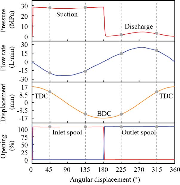
Figure 8 Variation of piston system parameters in the T. motor.
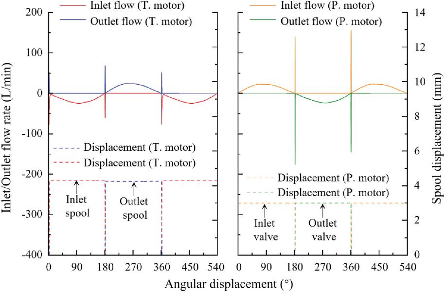
Figure 9 Spool displacement and valve port flow surges during inlet and outlet phases.
Figure 9 represents the flow surges through the valve ports corresponding to the displacement of the T. motor’s inlet spool (spool 1 in Figure 4) and outlet spool (spool 2 in Figure 4), and the displacement of the P. motor’s inlet/outlet distribution valve. During one full rotation of the main shaft, the distribution valve controls the corresponding piston chamber to complete two actions – intake and discharge, and during the switching process, sudden changes in system pressure cause flow surges to occur at the valve ports. For the P. motor, since the dual distribution valves open simultaneously, the high- and low-pressure oil circuits become momentarily short-circuited, resulting in more intense flow surges and aggravated leakage. In contrast, for the T. motor, the damping orifices in the valve body form an annular gap with a certain sealing capability between the pressure port and the tank port during spool switching, which effectively suppresses flow crossover, thereby enhancing the stability of the flow distribution process and improving the overall output performance under high pressure conditions of the motor.
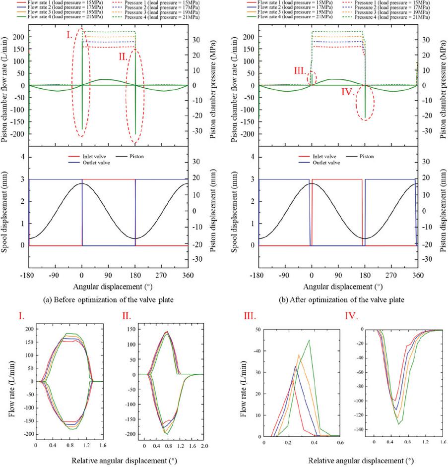
Figure 10 Performance curves of the piston chamber before valve plate optimization.
To prevent overlap in spool displacement within the P. motor’s flow distribution mechanism, the valve plate misalignment angle can be optimized to ensure that the inlet and outlet valves close earlier. As shown in Figure 10(b), this adjustment results in staggered displacement between the two valve spools during main-stage switching, thereby eliminating flow crossover. However, during the discharge phase, the outlet valve closes prematurely as the piston approaches the top dead center, while the inlet valve has not yet opened. This creates a dead zone in the flow distribution, leading to trapped oil and a rise in chamber pressure. Similarly, during the intake phase, the piston nears the bottom dead center, and the early closure of the inlet valve causes an ineffective stroke segment and a pressure drop in the chamber. These mismatches between piston motion and valve spool switching lead to additional leakage and flow surges, which are further aggravated under higher main-stage pressures, ultimately reducing the motor’s overall efficiency. Ideally, seamless coordination between the opening and closing of the inlet and outlet valves would eliminate these issues. However, due to numerous disturbances in real motor systems, this condition is practically unattainable and therefore not further discussed.
In contrast, the T. motor does not require adjustment of the valve plate misalignment angle. Its integrated damping-orifice structure within the distribution valve effectively prevents direct connection between the high- and low-pressure ports during switching. This inherently avoids flow surges caused by direct-through leakage at the principle level.
By adjusting the load relief valve pressure and inlet flow rate, the motor was operated stably under different pressure and speed conditions. An orthogonal experimental design was employed to select representative data points, and a 3D surface plot of volumetric efficiency variation was generated, as shown in Figure 11. The pilot-pressure control two-stage distribution scheme demonstrated excellent performance, maintaining a volumetric efficiency above 90% within a working pressure range of 25–40 MPa and remaining stable across different rotational speed conditions. Overall, the motor with the two-position three-way directional valve exhibited higher volumetric efficiency and a broader effective pressure range compared to the motor using dual pilot-operated check valves. It is noteworthy that, for the T. motor, increasing pressure led to greater leakage in the piston pair, resulting in a downward trend in volumetric efficiency. In contrast, the P. motor exhibited relatively stable efficiency because the accelerated response of the dual distribution valves at high pressure reduced through leakage, thereby compensating for the piston-pair leakage.
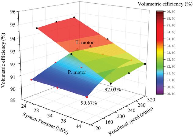
Figure 11 Volumetric efficiency comparison at various system pressures and speeds.
3.2 Prototype Motor Testing and Discussion of Results
To evaluate the performance of the pilot-pressure control two-stage flow distribution motor, comprehensive tests were conducted on the P. motor and T. motor using a hydraulic motor integrated test platform, as shown in Figure 12. The platform mainly consists of an integrated hydraulic power unit, a motor – pump power source, a test bench, hydraulic sensors, and a data acquisition cabinet. The parameters of the experimental setup are listed in Table 2. The output torque from the motor prototype is transmitted to the load end of the test bench, where a counter-torque motor is used to simulate the operation of a hydraulic pump actuator. The motor prototype, made of 7075-T6 aluminum alloy and employing a crank – connecting rod transmission mechanism, uses a main-stage distribution valve to control the inflow and outflow of the piston chamber, while the pilot-stage utilizes an end-face valve plate to control the distribution cycle, with a compensation plate additionally applied to offset clearance wear.
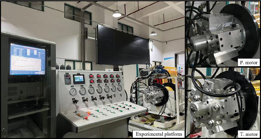
Figure 12 Photographs of the experimental platform and motor assembly.
Considering the strong influence of oil viscosity on leakage characteristics under high-pressure operation, the hydraulic oil temperature was maintained at using a temperature-controlled oil tank equipped with a heater and a cooler. For each set of experiments, the spring preload force on the compensation plate was set identically to control the initial clearance and mechanical efficiency of the distribution pair and, keeping them within a certain range, thereby facilitating the subsequent measurement of volumetric efficiency after pressure application.
Taking the T. motor as a representative example, the initial tests primarily focused on verifying the feasibility of the motor distribution principle. To simplify the hydraulic circuit, the pilot-stage and main-stage were branched in parallel from the same oil supply, which also implies that both stages experienced identical pressures. By adjusting the load end’s relief valve pressure, tests were conducted on the motor at no-load, 5 MPa, 7 MPa, 10 MPa, and 12 MPa operating conditions, with variable speed tests ranging from 60 to 140 r/min. The analysis focused on the motor’s output speed and torque, inlet flow rate, and inlet pressure characteristic curves. When the load relief valve setting pressure is zero, the motor is considered to be under no-load conditions, and the corresponding output characteristic curve is shown in Figure 13. The starting pressure of the motor is approximately 2.4 MPa. As the inlet flow rate increases, the motor speed, pressure, and torque rise accordingly. The pulsation rate remains low, indicating stable motor operation.
Table 2 Comprehensive test platform main parameters
| Parameter | Value | Unit |
| Maximum pressure | 31.5 | MPa |
| Maximum flow rate | 150 | L/min |
| Motor power | 55 | kW |
| Maximum speed | 0–3000 | rpm |
| Control oil pressure | 4 | MPa |
| Oil tank capacity | 1000 | L |
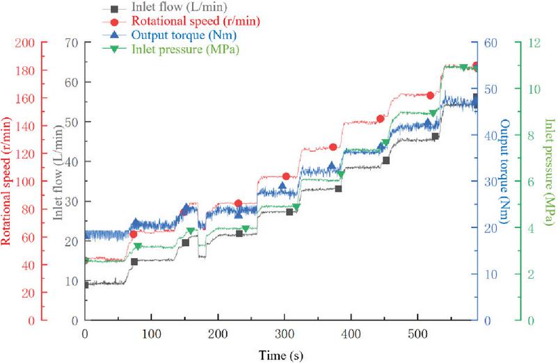
Figure 13 Motor performance curves without external load.
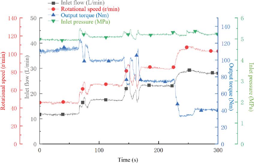
Figure 14 Motor performance curves at an inlet pressure of 5 MPa.
Subsequently, a loading test was performed on the motor. By jointly regulating the load relief valve pressure and the motor inlet flow rate, the inlet pressure was maintained at approximately 5 MPa while the rotational speed was progressively increased. The corresponding output performance curve is presented in Figure 14. Analysis of the curves indicates that the motor output speed increases with increasing inlet flow rate. To maintain stable pressure, the load-side pressure was reduced, resulting in a decrease in output torque. Except for fluctuations in the output parameters caused by changes in the input parameter settings during adjustment, all parameters exhibited minimal overall fluctuation. Calculations show that the volumetric efficiency of the motor under this operating pressure exceeds 98.5%.
The motor inlet pressure was increased and maintained at approximately 10 MPa, while the rotational speed was progressively raised from 60 to 140 r/min in increments of 20 r/min, with the resulting output performance curves shown in Figure 15. Compared with the operating condition at an inlet pressure of 5 MPa, all parameters except torque exhibited increased fluctuations. In addition, flow fluctuations were more pronounced at lower speeds, whereas pressure fluctuations became more significant at higher speeds. Under this condition, the motor experienced increased vibration and noise, significant leakage, and a volumetric efficiency of only around 75%.
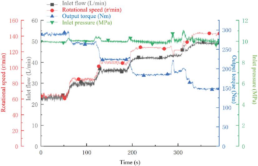
Figure 15 Motor performance curves at an inlet pressure of 10 MPa.
Performance tests of the two-position three-way valve motor were conducted under different pressure and speed conditions, and its corresponding volumetric efficiency was compared with that of the dual pilot-operated check valve motor, as shown in Figure 16. Overall, the T. motor exhibited higher volumetric efficiency than the P. motor, particularly under high-pressure conditions, and also demonstrated a higher maximum operating speed. Both motors maintained high volumetric efficiency below 7 MPa; however, as the pressure increased further, leakage became significant. For instance, the volumetric efficiency of the T. motor dropped to only 63.28% at 12 MPa and 60 r/min whereas that of the P. motor had already fallen to 60.5% at 10 MPa and 80 r/min. At high pressures, the volumetric efficiency of the T. motor increased with speed, indicating good speed stability, whereas the other motor showed a slight decrease in efficiency as speed increased. Preliminary tests confirmed the feasibility of employing a pilot-pressure control two-position three-way directional valve to achieve a two-stage flow distribution scheme, demonstrating technical advantages over the dual pilot-operated check valve configuration.
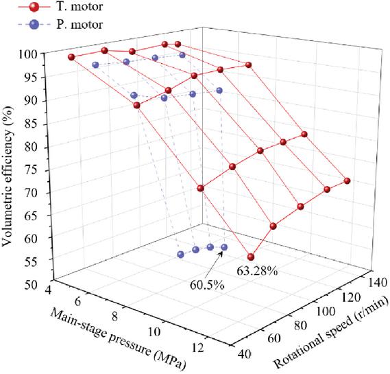
Figure 16 Variation of motor volumetric efficiency under different operating conditions.
By comparing the experimental results with the simulation, the trend that the volumetric efficiency of the T. motor decreases with increasing pressure is verified. However, it is observed that the maximum operating pressure achieved in the experiments is lower than that predicted by the simulation. This discrepancy is mainly attributed to insufficient manufacturing accuracy of the motor components, which limits the full realization of the motor’s performance potential. Future work will focus on reliability and durability studies of the motor.
To further utilize the pilot ratio characteristics of the distribution valve, a pressure-reducing valve was connected in series with the pilot-stage of the T. motor, enabling control of the distribution valve at a pressure lower than that of the main-stage. When the motor inlet pressure was 10 MPa and the pilot-pressure was 6.5 MPa, the corresponding output performance curves were obtained, as shown in Figure 17. Compared with Figure 15, the motor exhibited increased fluctuations at low speeds after the pilot-pressure was reduced, while the overall inlet flow and pressure fluctuations decreased. As the pressure acting on the distribution pair was reduced, leakage through the floating distribution clearance was effectively suppressed, resulting in a significant improvement of more than 10% in volumetric efficiency, as shown in Figure 18.
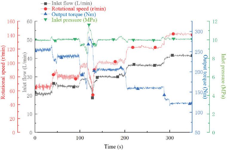
Figure 17 Motor performance curves under an inlet pressure of 10 MPa and a pilot-pressure of 6.5 MPa.
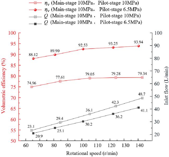
Figure 18 Variation of volumetric efficiency before and after pilot-stage pressure reduction.
In the proposed pilot-pressure control two-stage valve distribution method, the valve plate distribution is used only in the pilot stage and operates at a limited pressure, thereby ensuring a low level of leakage in the pilot stage. Owing to the sealing-oriented design of the valve spool, the majority of the leakage is expected to occur through the clearance of distribution pair, which is similar to the leakage behavior observed in conventional motors. However, due to the pilot ratio inherent in the distribution valve, the pressure acting on the distribution pair of the proposed motor is lower than that in conventional motors under the same main-stage pressure. This reduction in distribution-pair pressure effectively decreases clearance leakage, enabling conventional motors to improve their volumetric efficiency by adopting the two-stage valve distribution method. This approach provides a reference for overcoming the 25 MPa rated pressure limitation and achieving high-pressure operation.
4 Conclusion
This paper addresses the issue of severe wear and increased leakage in mainstream flow distribution mechanisms under high-pressure conditions by proposing a novel pilot-pressure control two-stage flow distribution method, applied to a radial piston hydraulic device. The existing dual pilot-operated check valve technology was optimized, and a novel two-position three-way directional valve scheme was proposed to achieve efficient sealing during the operation of the motor’s distribution valve, thereby significantly improving the volumetric efficiency of the motor under high working pressure. The main conclusions are as follows:
(1) This study presents a detailed investigation of the pilot-pressure control two-stage flow distribution principle. Based on mathematical modeling and simulation analysis, the effects of two technical schemes – the pilot-operated check valve and the two-position three-way directional valve – on flow distribution sealing and motor output performance were compared. Experimental tests on a motor prototype confirmed the feasibility of the proposed schemes.
(2) For the existing dual pilot-operated check valve, internal leakage during the flow distribution process remains a critical issue. Traditional approaches, such as adjusting the misalignment angle of the valve plate, are insufficient to address this problem. By contrast, designing a damping orifice structure in the two-position three-way directional valve effectively prevents through leakage during spool operation, significantly improving the motor’s volumetric efficiency.
(3) Leakage in the motor’s distribution pair is a key factor in the reduction of volumetric efficiency under high-pressure conditions. Existing experimental results demonstrate that reducing the pilot-stage pressure acting on the distribution pair from 10 MPa to 6.5 MPa increases volumetric efficiency by more than 10%, as the pilot ratio characteristic of the distribution valve lowers the pressure acting on the distribution pair and thereby suppresses leakage through the floating clearance. This mechanism provides a technical reference for overcoming the pressure limitations of conventional radial piston hydraulic motors.
Acknowledgment
This work was supported by the Young Scientists Fund of the National Natural Science Foundation of China (Grant No. 52305057) and the Fundamental Research Funds for the Central Universities (Grant No. ZQN-1104).
References
1. Y. Li, R&D of China’s strategic new industries [M]. Beijing: High-end hydraulic pneumatic and sealing components, 2021.
2. S. Sakama, Y. Tanaka, A. Kamimura, ‘Characteristics of Hydraulic and Electric Servo Motors,’ Actuators J., vol. 11, no. 1, pp. 11, 2022.
3. J. Pustavrh, M. Hočevar, P. Podržaj, et al., ‘Comparison of hydraulic, pneumatic and electric linear actuation systems,’ Scientific Reports J., vol. 13, no. 1, pp. 20938, 2023.
4. T. Kazama, ‘Comparison of power density of transmission elements in hydraulic, pneumatic, and electric drive systems,’ Mechanical Engineering Letters J., vol. 5, pp. 19-00139, 2019.
5. Parker Hannifin Corp. Radial Piston Motors [EB/OL]. [2023-01-10]. https://ph.parker.com/us/en/radial-piston-motors.
6. Kawasaki Motors Corp.Staffa Motor [EB/OL]. [2023-01-07]. http://www.kpm-usa.com/wp-content/uploads.
7. Intra-Italy Corp. Low-speed high-torque hydraulic motor [EB/OL]. http://www.intra-italy.com.
8. H. Ma, W. Liu, D. Wu, et al., ‘Modeling and analysis of the leakage performance of the spherical valve plate pair in axial piston pumps,’ Engineering Science and Technology, an International Journal J., vol. 45, pp. 101498, 2023.
9. Y. Chen, C. Hua, C. Tong, et al., ‘Volumetric efficiency in motor-driven two-dimensional piston pumps with leakage and reverse flow under high pressure,’ Scientific Reports J., vol. 14, no. 1, pp. 28963, 2024.
10. B. Xu, M. Hu, J. Zhang, et al., ‘Characteristics of volumetric losses and efficiency of axial piston pump with respect to displacement conditions,’ Journal of Zhejiang University – Science A J., vol. 17, no. 3, pp. 186–201, 2016.
11. W. Yin, J. Zhang, X. Wang, et al., ‘Volumetric efficiency degradation prediction of axial piston pump based on friction and wear test,’ Heliyon J., vol. 10, no. 17, pp. 2024.
12. L. Li, J. Chen, L. Gu, et al., ‘Variable displacement distributor with valve control for axial piston pump/motor,’ Journal of Zhejiang University:Engineering Science J., vol. 48, no. 1, pp. 29–34, 2014.
13. K. Pate, I. Azzam, F. Breidi, et al., ‘Digitalization of Radial Piston Pumps through Internal Mechanically Actuated Designs,’ J., vol. 12, no. 11, pp. 425, 2023.
14. Imenco. Imenco Bauer and Diinef Digital Motor [EB/OL]. [2025-01-26]. https://imenco.no/imenco-bauer-hydraulics-and-diinef-launch-digital-motor.
15. J. Man, J. Zhao, Y. Wang, et al., ‘Working Characteristics of Crankshaft Swing Cylinder Water Hydraulic Motor with Flow Distribution Valve,’ Transactions of the Chinese Society for Agricultural Machinery J., vol. 54, no. 1, pp. 450–458, 2023.
16. T. Guo, T. Lin, H. Ren, et al., ‘Modeling and theoretical study of relief chamfer method for reducing the flow ripple of a spool valves distribution radial piston pump,’ J., vol. 235, no. 19, pp. 3819–3832, 2021.
17. Danfoss. Digital Displacement Pumps and Motors [EB/OL]. [2023-01-26]. https://www.danfoss.com.
18. W. Shen, S. Nie, F. Yin, et al., ‘Structure Design and Simulation Analysis of a New Type Low-speed Large-torque Water Hydraulic Motor,’ Hydraulics & Pneumatics J., no. 06, pp. 17–21, 2019.
19. N. Xu, J. Wang, W. Min, et al., ‘The Effect of Piston Pump Spherical Valve Plate Triangular Groove Flow Area on Outlet Flow Pulsation,’ Hydraulics & Pneumatics J., vol. 42, no. 04, pp. 19–24, 2022.
20. Y. Chen, J. Zhang, B. Xu, ‘Multi-objective optimization of micron-scale surface textures for the cylinder/valve plate interface in axial piston pumps,’ Tribology International J., vol. 138, pp. 316–329, 2019.
21. L. Kumar, N. P. Mandal, ‘Effect of valve plate silencing grooves on flow and pressure fluctuation in fixed displacement radial piston pump,’ Journal of Computational & Applied Research in Mechanical Engineering J., vol. 13, no. 1, pp. 55–66, 2023.
22. G. K. Seeniraj, M. Ivantysynova, Impact of Valve Plate Design on Noise, Volumetric Efficiency and Control Effort in an Axial Piston Pump; proceedings of the ASME 2006 International Mechanical Engineering Congress and Exposition, F, 2006 [C].
23. D. Richardson, F. Sadeghi, R. G. Rateick, ‘Dynamic Modeling of Floating Valve Plate Motion in an Axial Piston Pump,’ Tribology Transactions J., vol. 61, no. 4, pp. 683–693, 2018.
24. D. Gao, H. Ma, J. Liu, et al., ‘Numerical Simulation on Loading Characteristics of Port Plate Pair with Non-smooth Surface for Water Hydraulic Motor,’ Hydraulics & Pneumatics J., no. 11, pp. 61–69, 2018.
25. H. Ma, D. Gao, S. Wu, et al., ‘Experimental Study on Friction-wear for Valve Plate with Bionic Non-smooth Surface of Hydraulic Motor,’ Journal of Mechanical Engineering J., vol. 54, no. 13, pp. 142–152, 2018.
26. S. Nie, Z. Wan, W. Liu, ‘Theoretical Research of A New Type Valve Plate,’ Machine Tool & Hydraulics J., no. 03, pp. 88–90, 2004.
27. J. M. Bergada, J. Watton, S. Kumar, ‘Pressure, Flow, Force, and Torque Between the Barrel and Port Plate in an Axial Piston Pump,’ Journal of Dynamic Systems Measurement and Control J., vol. 130, pp. 2018.
28. T. Guo, T. Luo, T. Lin, Radial piston hydraulic device distributing flow by pilot operated check valves and operating method thereof, US12129874B2 [P]. [2024-10-29].
29. J. Zhao, L. Liu, ‘Influence of reversing impact load on performance of a two-step unloading pilot-operated check valves,’ Journal of the Brazilian Society of Mechanical Sciences and Engineering J., vol. 40, no. 6, pp. 295, 2018.
30. Y. Yin, D. Wang, J. Fu, et al., ‘Effect of Dynamic Pressure Feedback Orifice on Stability of Cartridge-Type Hydraulic Pilot-Operated Relief Valve,’ Chinese Journal of Mechanical Engineering J., vol. 36, no. 1, pp. 85, 2023.
31. W. Wei, H. Jian, Q. Yan, et al., ‘Nonlinear modeling and stability analysis of a pilot-operated valve-control hydraulic system,’ J., vol. 10, no. 11, pp. 1687814018810660, 2018.
32. T. Guo, T. Luo, T. Lin, Radial piston hydraulic device distributed by pilot operated check valves, US11781537B2 [P]. [2023-10-10].
Biographies

Tong Guo received his Ph.D. degree in Mechanical Engineering from Xi’an Jiaotong University in 2016. From 2016 to 2019, he worked at the Research Institute of Petroleum Exploration and Development (RIPED), PetroChina, where he was engaged in research on oil production engineering technologies. He later joined Huaqiao University, where he is currently an Associate Professor at the College of Mechanical Engineering and Automation. His research interests include high-performance hydraulic components, hydrodynamic and electro-hydraulic transmission systems, energy-saving technologies, and downhole flow control techniques for oilfield development.

Fumin Que received the B.E. degree in the mechanical engineering from Huaqiao University in 2023. He is currently pursuing the M.S. degree with the College of Mechanical Engineering and Automation, Huaqiao University. His research encompasses high-performance hydraulic components including motors, flowmeters, and pumps.

Xinming Li received the B.E. degree in the mechanical engineering from Huaqiao University in 2024. He is currently pursuing the M.S. degree with the College of Mechanical Engineering and Automation, Huaqiao University. His research interests include high-performance hydraulic component, control of hydrodynamic and electro-hydraulic transmission systems.

Hao Liu received his Master’s degree in Mechanical Engineering from Harbin Institute of Technology in 2013. From 2013 to now, he worked at Beijing Tianma Intelligent Control Technology Co., Ltd., where he was engaged in research on Mining machinery and equipment.

Tianliang Lin received his B.E. degree from Fuzhou University in 2006 and his Ph.D. degree in Fluid Power Transmission and Control from Zhejiang University in 2011. He is currently a Professor and Doctoral Supervisor at the College of Mechanical Engineering and Automation, Huaqiao University, where he also serves as the Dean. His research interests include electro-hydraulic control, intelligentization of construction machinery, and energy-saving technologies.
International Journal of Fluid Power, Vol. 27_3, 511–538
doi: 10.13052/ijfp1439-9776.2732
© 2026 River Publishers