Hydraulic Hybrid Solution for Peak Power Reduction in Electrified Mobile Machine
Mikko Huova
Tampere University, Automation Technology and Mechanical Engineering
Korkeakoulunkatu 6, 33720 Tampere, Finland
E-mail: mikko.huova@tuni.fi
ORCID: https://orcid.org/0000-0001-6384-7688
Received 24 November 2025; Accepted 20 September 2026
Abstract
Enhancing the energy efficiency of mobile machines is essential for advancing sustainable off-road equipment. Electrification can lead to decreased power losses and local emissions produced. However, full electrification of a mobile machine requires typically a number of high-power electric drives, increasing the manufacturing cost of the machine. This study explores a hydraulic hybrid system implemented on an electrified wheel loader, combining digital hydraulics with a hydraulic accumulator to enable fast dynamics and precise control. Single-accumulator and double-accumulator configurations are compared and discussed. A simulation model making use of measured real-world load cycle data is created to study the potential. The results indicate significant potential to downsize the electric drive. The study provides insights into the integration of hydraulic energy storage and control technologies in next-generation mobile machinery.
Keywords: Mobile machine, wheel loader, hydraulic hybrid, electrification, digital hydraulics.
1 Introduction
Electrification is currently a notable trend in off-highway and mobile machinery, driven by the urgent need to reduce local emissions and meet increasingly stringent environmental regulations. Replacing internal combustion engines (ICEs) with electric motors (EMs) and batteries provides a direct pathway to zero local carbon emissions. In addition, the elimination of particle and gaseous emissions that impact human health is particularly beneficial in urban and environmentally sensitive areas.
However, the transition from diesel-powered machines to battery-electric machines presents unique technological challenges that differ from those currently addressed in the automotive sector. Two key challenges, especially relevant to work functions, are as follows: (1) high-torque and therefore expensive prime movers, i.e. EMs, and (2) inefficient hydraulic architectures.
A direct one-to-one replacement of an ICE with an EM often leads to a high-torque and costly prime mover. Due to the significant variation in machine work cycles, a conservative approach to electric motor sizing is typically required. Consequently, the motor is not sized based on its short-term maximum torque, but rather on its much lower continuous torque rating. Such an approach compromises the economic feasibility of the machine. Furthermore, the challenge of limited installation space – already intensified by the large battery – becomes even more pronounced.
Conventional hydraulic systems, which typically rely on throttling-controlled actuators and centralized system layout, are inherently inefficient and prone to substantial energy losses. In battery-powered machines, these inefficiencies directly reduce operating time, thereby limiting the practicality and productivity of electrified solutions.
To address these challenges, this paper explores a combination of two solutions: (1) hydraulic hybridization, and (2) independent metering leak-free digital hydraulics. The first challenge – oversized prime movers – is addressed by integrating hydraulic energy storage into the system architecture. This allows peak power demands of the work hydraulics to be met without oversizing the EM, enabling a more balanced and cost-effective design. The second challenge – inefficient hydraulic architectures – is alleviated through the use of digital hydraulic valve systems (DVSs), which significantly reduce throttling losses by means of independent metering [1–4] and enable deterministic, energy-efficient control of actuators.
Hydraulic hybrids can be implemented using a variety of system architectures as discussed in [5]. Some architectures focus on energy recuperation from a single actuator such as the lift cylinder of a crane or boom of an excavator [6, 7]. Others offer more general solutions allowing energy recovery or peak power shaving of multiple actuators [8–11].
This paper introduces a novel double-accumulator hydraulic hybrid approach, which is studied in a simulated wheel-loader application using real-world load cycle data [12]. The proposed architecture builds upon the single-accumulator hybrid previously studied in ICE-powered machine [13]. The first contribution of this paper is a performance comparison between the proposed hydraulic hybrid and a conventional non-hybrid hydraulic system in an electrified machine. Additionally, the benefits of the double-accumulator concept over the single-accumulator approach are assessed.
The second contribution of the paper is the design of an accumulator management algorithm. The flow of hydraulic power between the system and the two accumulators is controlled via digital hydraulic flow control units (DFCUs), which are based on parallel connected on/off-valves. The algorithm controls the DFCUs to limit the peak power required from the EM-driven main pump and ensures energy-efficient accumulator charging during low-power phases of the load cycle. Together, these contributions offer an alternative pathway toward the electrification of mobile machinery – one that does not overlook the potential of modern hydraulic solutions such as hydraulic hybrids.
2 System Description and Modelling
The system studied is an electric-hybrid wheel loader prototype, built to serve as a research platform. The simplified hydraulic circuit diagram of the work functions is shown in Figure 1(a). Furthermore, a five-valve DFCU (c) and its drawing symbol (b) are shown. For clarity, the lift, stabilizer, and tilt actuators are depicted as single cylinders, although in reality they are parallel-connected double-cylinder configurations. The purpose of the stabilizer cylinders, which are mechanically coupled between the boom and the machine front frame, is to maintain the orientation of the bucket during lift actuator operation.
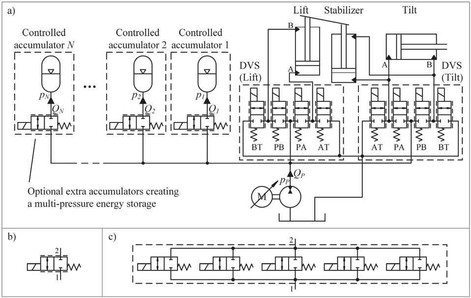
Figure 1 (a) Simplified hydraulic circuit diagram; (b) drawing symbol of a DFCU; (c) a DFCU comprising five on/off-valves.
A simulation model of the machine, focusing on the digital hydraulic work functions, has been developed in [14]. The Simulink-based model comprises the mechanism model and hydraulic model. The mechanism is modelled using Simscape Multibody, while the hydraulic model is based on custom made hydraulic component models.
To evaluate system performance, a measured load cycle from a wheel loader performing a gravel loading -cycle is used as the reference scenario. A detailed description of how the measured load force and piston positions are used to simulate the load cycle is given in [14].
This paper focuses on modelling of the hydraulic hybrid concept, which includes the accumulators, their associated DFCUs, and a speed-controlled pump. Throttling losses related to the accumulator control can be minimized by assigning distinct pressure levels to each accumulator. While this study focuses on single- and double-accumulator configurations, the concept is scalable to any number of accumulators, as illustrated in Figure 1.
2.1 Accumulator Model
The accumulator pressure and , are modelled using the adiabatic gas law:
| (1) |
where is the pre-charge pressure of the accumulator is the nominal size of the accumulator and is the flow rate into the accumulator. The accumulator flow rates and are modelled as a sum flow of the parallel connected on/off-valves in the DFCUs. The typical square root equation of a turbulent orifice is modified according to work presented in [15] to avoid the infinite derivative around zero pressure difference:
| (2) |
where stands for is the number of parallel connected valves in the DFCU, is the opening of the th valve in the DFCU, is the flow capacity of the th valve, is the pressure difference over the DFCU i.e. , and is the critical pressure difference (0.1 MPa) under which the flow is assumed to turn into laminar. The opening of an on/off-valve is a value between 0 and 1, where 1 means complete opening of the valve. The valve dynamics are simplified in this study such that the valve opening follows the valve command after a delay with a rate limited to .
2.2 Pump Model
Pump flow rate is modelled as
| (3) |
where is the angular speed of the pump, is the radian displacement and represents the flow rate resulting from all volumetric losses. The load torque induced by the pump is defined as
| (4) |
where is the pump pressure and is the torque loss. The suction line pressure is assumed to be zero thus the pressure difference over the pump is assumed always positive.
The loss models are based on the models presented in [16] and have been further refined to better align with the measured pump loss data. The loss models are fit according to the measured losses of Bosch Rexroth A4FO28 pump presented in the measurement report [17]. The torque losses are modelled as
| (5) |
The loss parameter values used for the coefficients are given in Table 1. The volumetric loss model is less elaborate containing only three terms:
| (6) |
Table 1 Parameters of the pump loss model
| Torque loss coefficient | |
| Torque loss coefficient | |
| Torque loss coefficient | |
| Torque loss coefficient | |
| Torque loss coefficient | 700 s Pa rad -1 |
| Torque loss coefficient | |
| Torque loss coefficient | |
| Volumetric loss coefficient | |
| Volumetric loss coefficient | |
| Volumetric loss coefficient |
The volumetric loss coefficients are presented in Table 1 as well. Mechanical input power and hydraulic output power of the pump are therefore
| (7) | |
| (8) |
Power loss resulting from the above model, is pictured in Figure 2 for pump size of . The pump losses are scaled based on the radian displacement of the pump as shown in Equations (5) and (6) making it possible to simulate various pump sizes.
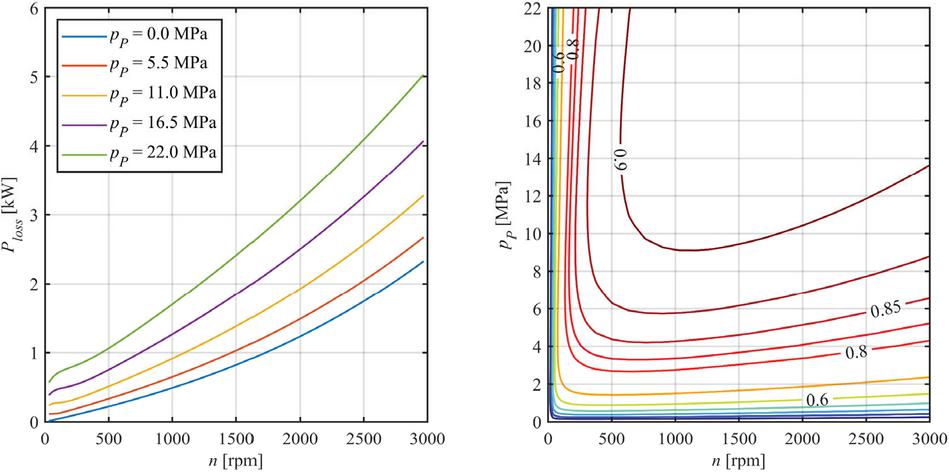
Figure 2 Modelled power loss (left) and total efficiency (right) of a pump.
2.3 Electric Motor Model
Electric motor is modelled with first-order rotational speed dynamics and relatively simple loss model. The electric motor input power is
| (9) |
where is the output torque of the electric motor and is the power loss. The power loss is defined as
| (10) |
where is the maximum torque of the electric motor and and are loss coefficients. The loss coefficients are set according to the efficiency map available in [18] and they are presented in Table 2. The motor loss model can be adjusted linearly to different motor sizes by setting the maximum torque parameter accordingly [19]. Figure 3 presents the power losses and efficiency of an electric motor with 189 Nm maximum torque.
Table 2 Parameters of the electric motor model
| Loss coefficient | |
| Loss coefficient | |
| Loss coefficient |
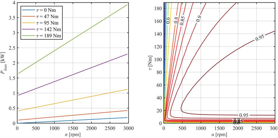
Figure 3 Modelled power loss (left) and efficiency (right) of an 189 Nm electric motor.
2.4 Model Parameterization
The rest of the simulation model parameters related to the hydraulic hybrid are given in Table 3. Each accumulator is controlled using a DFCU comprising five parallel on/off-valves. In this study, each valve has a unique flow capacity, which can be implemented in practice using series orifices. Despite this, the accumulator DFCUs are controlled as if they were unary-coded. In other words, the DFCU output is adjusted by either opening or closing valves. This avoids the synchronization challenge inherent in control methods for binary-coded DFCUs, which require simultaneous opening and closing of valves. To improve resolution at small openings, a non-uniform coding scheme is used: the relative flow capacity of the th valve is , resulting in the flow capacities listed in Table 3.
Table 3 Simulation model parameters
| Pump displacement | |
| Valve flow capacities | |
| Valve delay | 6 ms |
| Valve movement time | 4 ms |
| Accumulator nominal sizes and | |
| Accumulator 1 pre-charge pressure | 17 MPa |
| Accumulator 2 pre-charge pressure | 6 MPa |
| Max torque of the electric motor | 189 Nm |
3 Control Design
The objective of the hydraulic hybridization in this paper is to allow the accumulators to supplement the pump flow during peak demand periods. This approach allows for downsizing the main pump and avoids the need to oversize the electric motor. The control principle for flow assistance is straightforward: when the maximum rotational speed of the pump would be exceeded, an accumulator – selected to minimize throttling losses while maintaining sufficient pressure – is activated to provide additional flow. The combined output of the pump and accumulator then meets the required flow demand.
The accumulator charging strategy is designed such that it permits charging during periods of low to moderate actuator flow demand. By setting the algorithm parameters appropriately, charging can also be restricted to periods when actuator flow is zero. If charging is allowed during actuator operation, care must be taken to avoid conditions that would result in significantly increased power losses, either in the accumulator DFCUs or in the DVSs of the work functions. In practice, this is evaluated by comparing the pump pressure required for accumulator charging with the estimated pump pressure resulting from actuator loads. Charging is prevented, if the difference between the two pressures exceeds a defined threshold.
The accumulator DFCU is controlled in this case using a pulse number modulation (PNM), where the control signal corresponds to the number of opened on/off-valves. Therefore, this value is an integer between zero and the number of valves .
The accumulator management algorithm is implemented as a state machine, with each state defining specific control rules for determining the DFCU commands and , as well as the pump speed reference . The main inputs of the algorithm are as follows: pump rotational speed reference generated by the actuator controller, accumulator pressures and , pump pressure estimate produced also by the actuator controller and low pass filtered pump pressure . The low-pass filtering is performed using an asymmetric first-order filter, with a fast time constant for pressure increase , and a slower time constant for pressure decrease . This results in low-pass filtered signal, that effectively rejects high-frequency noise and oscillations, while remaining responsive to rising pump pressure. Figure 4 illustrates the state machine, including its states, transitions, and associated transition conditions. These transitions are governed by Boolean-valued functions, which are detailed in the following section.
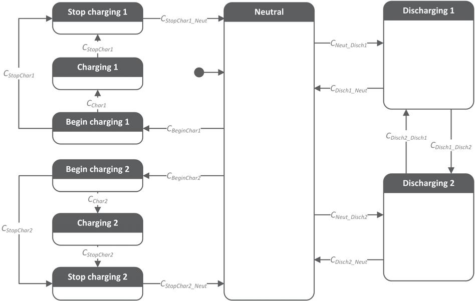
Figure 4 State machine controlling the charging and discharging of the accumulators.
3.1 State Transition Conditions
The state Neutral is the default state to which the algorithm initializes and where the DFCUs are kept closed ( and ) and the pump rotational speed is passed through as it is . When the flow demand increases and the pump rotational speed exceeds the maximum value , discharging of an accumulator begins. However, this is possible only if at least one of the transition conditions or is true. The conditions are defined as
| (11) | ||
| (12) |
Conditions and consider, whether the accumulator pressure is high enough compared to filtered pump pressure and pre-charge pressure of the accumulator:
| (13) |
The condition is similar for both accumulators and the symbol in above condition refers to 1 or 2 depending on which accumulator is considered. As seen in the conditions above, the accumulator with lower pressure is selected, if the pressure levels of both accumulators are sufficient. This is done to minimize throttling losses involved in discharging. If later, discharging from the selected accumulator becomes infeasible, the discharged accumulator is changed according to following conditions:
| (14) | |
| (15) | |
| (16) |
where is a pressure threshold value smaller than . The neutral state is returned, if discharging is no longer necessary or possible from either of the accumulators. However, discharging is not immediately halted, when the pump rotational speed decreases below the limit to prevent chattering. Instead, a hysteresis margin is introduced to ensure stable operation.
| (17) | ||
| (18) |
Charging of an accumulator is a three-state process as shown in Figure 4. If one of the accumulators needs charging, the corresponding Begin charging state is entered. The purpose of this state is to pressurize the pump line such that the pressure difference over the accumulator DFCU becomes small prior to opening of the DFCU. This allows minimization of unwanted pressure and flow fluctuations. The DFCU is opened only after the condition becomes true and the state Charging is entered. If at any time, when the states Charging or Begin charging are active, a need to stop the charging procedure arises, the state Stop charging is entered. In this state, the charging is gradually reduced to zero. Only then, the neutral state is again entered.
The conditions for entering the Begin charging states are
| (19) | ||
| (20) |
where and are accumulator pressure errors from their nominal values. The pressure errors are defined as
| (21) |
where is the desired nominal pressure level of the accumulator. If both accumulators would require charging, the one with bigger pressure error is charged first. is a threshold value used to avoid entering the charging state, if already considerable rotational speed is needed to feed the actuators. Charging should be also avoided, if the estimated pump pressure , which is based on the load pressure of the actuators, is much smaller than the current accumulator pressure. Otherwise, significant increase of throttling losses would occur in the actuator control valves. The condition is arranged such that whenever the flow rate to actuators is zero, charging may begin independent of the estimated pump pressure. The condition for advancing to state Charging is simple
| (22) |
where represents the estimated number of control sample intervals required for the pump pressure to reach the accumulator pressure level. The number of sample intervals is predicted using a first-order estimate
| (23) |
where is set as 0.1 MPa to avoid division with zero and is the filtered pump pressure of previous sample time. As defined in condition the state Charging is entered, when becomes smaller than a user set timing advance parameter . The purpose of this is to begin commanding the DFCU open already slightly before the (lowpass filtered) pump pressure reaches the accumulator pressure. This is done to account for valve delays.
If an actuator flow demand exceeds the threshold value while the states Begin charging or Charging are active, the state Stop charging is entered. The same is true, if the pressure error of the accumulator becomes small enough or the difference between the accumulator pressure and estimated actuator load pressure becomes too big as defined in the transition condition
| (24) |
where and are threshold values smaller than and , respectively. The state Neutral is entered when following condition holds
| (25) |
where is the rotational speed reference of previous controller sample time, is the user set step size allowed in one controller sample time interval and is the commanded accumulator DFCU opening of the previous sample time.
3.2 Discharging Functionality
When a discharging state (Discharging 1 or Discharging 2) has been entered, following equations are used to control the corresponding DFCU opening or and pump rotational speed . Firstly, the target value for the accumulator flow rate is calculated:
| (26) |
where is the main pump displacement per revolution. The possible flow rates enabled by the DFCU with different valve command combinations are analysed next:
| (27) |
where is a pre-calculated vector of net flow capacities of the DFCU with the different valve command candidates. For a five-valve DFCU, is
| (29) |
The DFCU command is selected using a cost function balancing between flow error and valve activity. Therefore, a flow error is calculated
| (30) |
The flow error term is modified such that all but last element (which correspond to every valve commanded open) are set to infinite, if the calculated flow rate of the corresponding candidate is insufficient, i.e. less than . This is done to guarantee sufficient accumulator flow rate whenever possible. The second term of the cost function sw reduces the valve activity. All valve command candidates receive a switching cost of except the selected command of previous sample time, for which the cost term is set to zero. The candidate which minimizes the following cost function , is set as the DFCU command:
| (31) |
Finally, the rotational speed command for the pump is generated based on the calculated flow rate of the selected valve command and the original rotational speed reference:
| (32) |
where is the index of the optimal DFCU command candidate, that minimizes the cost function . If the flow rate of the selected valve command candidate is smaller than the desired accumulator flow rate , the accumulator flow rate can be supplemented by the second accumulator, provided that its feasibility condition is true. This functionality is needed, when pressure difference over the DFCU of an accumulator becomes small and the flow capacity of the DFCU is no longer adequate. Equations from (26) to (32) are then reused for the second accumulator with one significant difference: instead of using as the target rotational speed, the is used to take into account the already defined accumulator flow.
3.3 Charging Functionality
When the states Begin charging 1 or Begin charging 2 become active, the pump rotational speed is gradually increased towards a target charging speed, where the flow demanded by the actuators is exceeded by the user set charging flow rate . Rampwise increase is achieved using following equation:
| (33) |
In the states Charging 1 or Charging 2, the actual charging occurs, by gradually opening the DFCU and further increasing the pump rotational speed if the target speed is not reached yet (Equation (33)). The DFCU opening is increased by a user set step size in each sample time and limited to as the maximum. The scalar valued opening is rounded upwards and defines the number of opened valves in the DFCU.
When the states Stop charging 1 or Stop charging 2 become active, the rotational speed of the pump is ramped down towards again with the step size . Whether the closing of the DFCU begins immediately or not, depends on the condition on which the state has been entered. If there is a flow demand from the actuators, i.e. , ramping down of the DFCU command begins immediately. Otherwise, the ramping down of the DFCU command is begun, when the pump rotational speed is sufficiently close to zero. Firstly, the remaining deceleration period of the pump is calculated as the number of controller sample time intervals
| (34) |
When becomes smaller than the desired timing advance , the ramping down of the DFCU command begins. Similar to opening of the DFCU, the closing of the DFCU is executed ramp-wise using the user set step size . The scalar valued opening is rounded downwards in this case and the ramping down continues until DFCU opening of zero is reached after which the charging is finished, and the neutral state is entered again.
3.4 Controller Parameters
The controller parameters are listed in Table 4. In addition, the control algorithm utilizes the pump displacement and the flow capacity information of the on/off-valves in the accumulator DFCU, which are provided in Table 3.
Table 4 Controller parameters for the accumulator management algorithm
| Controller sample time | 10 ms |
| Min pressure, acc. | 17.5 MPa |
| Min pressure, acc. | 6.5 MPa |
| Nominal pressure, acc. | 22 MPa |
| Nominal pressure, acc. | 11 MPa |
| Number of valves | 5 |
| Positive time constant | 20 ms |
| Negative time constant | 200 ms |
| Switching cost weight | |
| Maximum pump speed | 3000 rpm |
| Speed hysteresis | 300 rpm |
| Pressure threshold on | 0.3 MPa |
| Pressure threshold off | 0.1 MPa |
| Speed step size | 120 rpm |
| Timing advance | 7 |
| Target charging flow rate | |
| DFCU command step size | 1 |
| Timing advance | 1 |
In this study, accumulator charging is limited to idle periods of the work functions. This is achieved by setting and . The minimum allowed accumulator pressures, and are set 0.5 MPa above the corresponding pre-charge pressures. The nominal accumulator pressures, and are set 5 MPa above the pre-charge pressures to define the active operating range of the accumulators. The number of parallel on/off-valves, , in the accumulator DFCUs is selected based on the required maximum flow capacity, the desired flow control resolution, and the characteristics of the available components.
To limit the valve activity of the accumulator DFCU during controlled discharging, the switching cost weight is increased until the flow control accuracy begins to deteriorate. Consequently, unnecessary on/off-valve switchings are avoided during controlled accumulator discharging. The maximum pump speed is set according to the pump performance limit. The speed hysteresis is chosen sufficiently large to prevent repeated transitions between the discharging and neutral modes. The pressure threshold is set to a relatively low level of 0.3 MPa, resulting in a small hysteresis that must be exceeded before either charging or discharging mode can be activated. The second pressure threshold, , is set lower than to ensure proper hysteresis operation.
The speed step size parameter and the DFCU control timing advance are adjusted to achieve rapid initiation of the accumulator charging process while avoiding excessive pump pressure overshoot relative to the accumulator pressure and, conversely, backflow from the accumulator to the pump line. The target charging flow rate is set as low as possible to minimize pressure losses over the accumulator DFCU while remaining sufficiently high to enable adequate accumulator charging during the short idle periods of the work cycle. The DFCU command step size is set to 1, resulting in a 50 ms transition time from fully closed to fully open when charging is initiated. Similarly, the accumulator DFCU is closed at the same rate when charging is terminated. A fast ramp is employed to achieve a slightly smoothed on/off-type behaviour of the DFCU during charging, where minimization of throttling losses over the DFCU is desirable. Finally, the timing advance parameter is adjusted similarly to to achieve controlled closure of the DFCU when charging is terminated.
4 Simulation Study
The system response and energy consumption of components are analysed in the following sections through simulation. The work cycle analysed is presented in Figure 5.
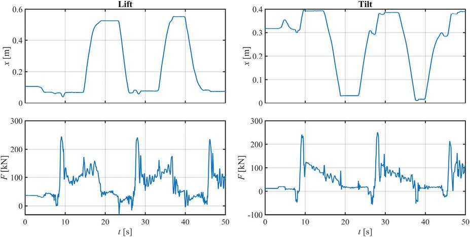
Figure 5 Work cycle analysed.
The baseline, to which the hydraulic hybrids are compared to, is the digital hydraulic system without hydraulic accumulators. In addition to the baseline, configurations with one accumulator and two accumulators are studied to evaluate the impact of additional accumulator on throttling losses. Finally, two parameter studies are presented to assess (1) the effect of the accumulator pressure level on the energy losses and (2) the balance between the electric motor downsizing and total energy loss.
4.1 Baseline
To evaluate the performance of the hydraulic hybrid, a non-hybrid baseline is required. The baseline simulation results are presented in Figure 6. Here, the pump displacement is set to , limiting the pump’s rotational speed to 3000 rpm, as shown in the upper left diagram. Pump pressure is presented in the top-right diagram, both before and after the low-pass filtering. Actuator and pump flow rates are shown in the middle of the left column. They are virtually identical due to the absence of the accumulators.
The bottom-left diagram illustrates the load torque imposed on the electric motor by the pump, while the bottom-right presents the cumulative energy losses over the load cycle. These losses include contributions from the electric motor, the pump, and throttling losses associated with the digital valve systems of the lift and tilt actuators. Despite the use of digital hydraulic independent metering valves, throttling losses remain relatively high compared to pump and electric motor losses. With these pump and electric motor loss models, the pump losses are 59% greater than those of the electric motor.
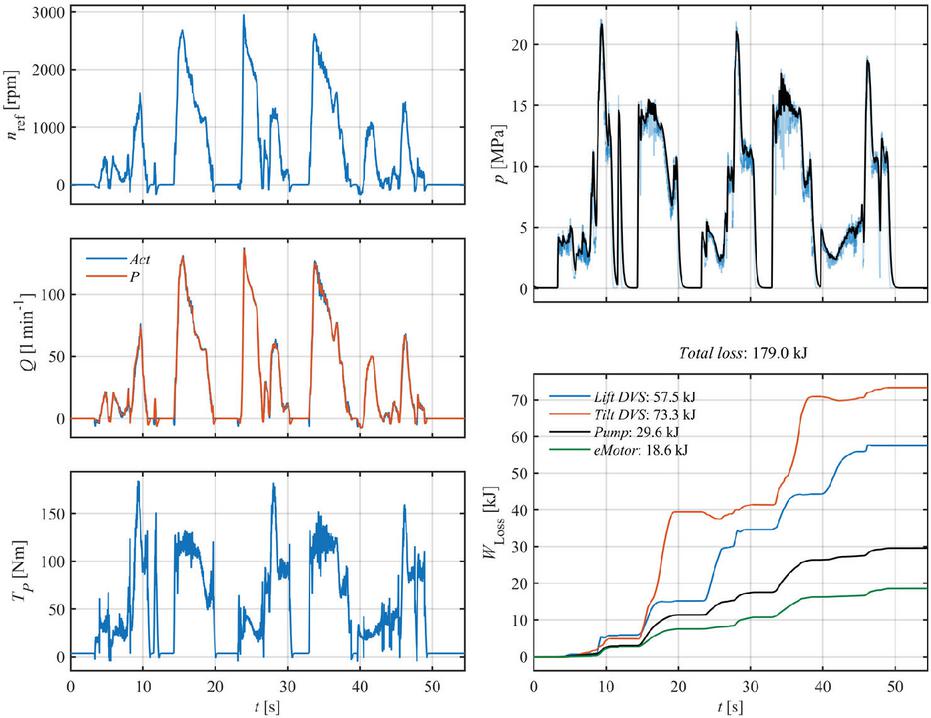
Figure 6 Baseline simulation results without hydraulic hybridization.
4.2 Hydraulic Hybrid with One Accumulator
Figure 7 presents the simulation results for the single-accumulator hydraulic hybrid configuration. In this setup, the pump displacement is reduced to , and the accumulator management algorithm limits the pump’s rotational speed to 3000 rpm. This represents a reduction of approximately 33% in pump displacement compared to the baseline configuration.
The reduction of the pump size allows also downsizing of the electric motor such that maximum torque of the motor is set to 132 Nm, which is 30% lower than in the baseline configuration. Accumulator 2 is disabled, and the accumulator 1 is sized at 20 litres, ensuring that the total accumulator volume remains consistent between the single- and double-accumulator cases.
It is worth noting that the maximum torque of the electric motor is momentarily exceeded in the simulation. However, this overshoot is brief, and it originates from the torque loss model of the pump as discussed later in Section 4.3.
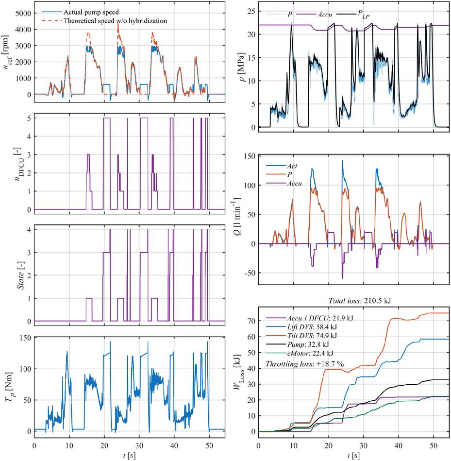
Figure 7 Simulation results of the hydraulic hybrid with single controlled accumulator.
In Figure 7, there are two rotational speed signals presented, blue being the actual pump rotational speed and red being a theoretical rotational speed assuming accumulator flow would be zero, i.e. operation without the hydraulic hybridization. In addition to the pump pressure, the accumulator pressure is presented as well.
The two middle diagrams in the left column show the DFCU command value and the current state of the accumulator management algorithm. The states are defined as follows: (0) Neutral, (1) Discharging, (2) Begin charging, (3) Charging, (4) Stop charging.
The flow rate diagram now includes the flow rate into the accumulator, and the energy loss diagram has been extended to show throttling losses associated with the accumulator DFCU. The throttling loss is relatively high as the accumulator pressure has been set to a high level to support the pump under all load conditions. Both pump and electric motor energy losses increased slightly when compared to the baseline.
4.3 Hydraulic Hybrid with Two Accumulators
The next step involves enabling the second accumulator and setting the volume of both accumulators to 10 litres each. All the signals presented previously for accumulator 1 (purple line) are now also presented for accumulator 2 (yellow line) in Figure 8.
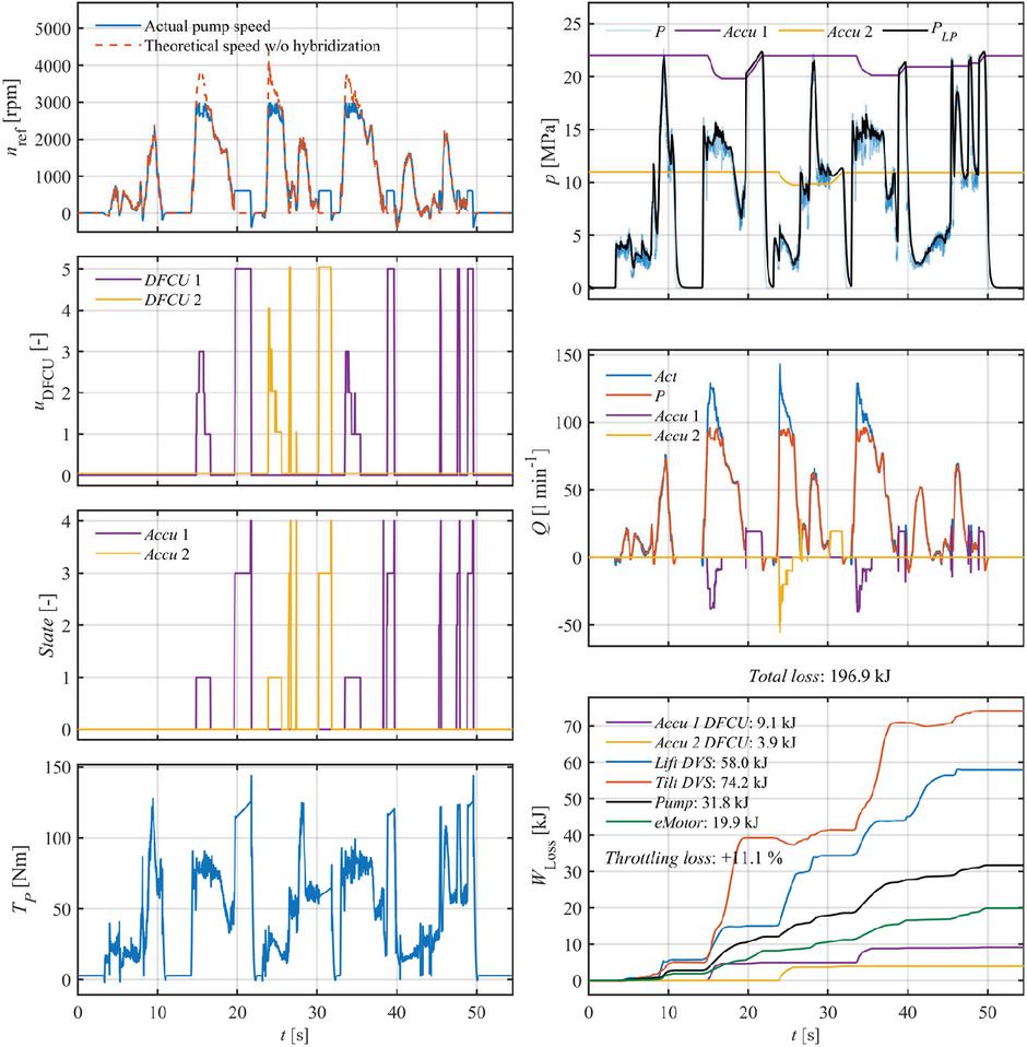
Figure 8 Simulation results of the hydraulic hybrid with two controlled accumulators.
The throttling losses associated with the DFCUs controlling the accumulator flows are reduced approximately 41% in comparison to the single accumulator hybrid configuration. Additionally, both the electric motor and pump losses decrease slightly.
To provide a more detailed view of system dynamics during discharging and charging phases, an excerpt of the simulation is shown in Figure 9. Initially, a high flow rate is required by the actuators, and up to three valves are opened within the DFCU of accumulator 1 to limit the rotational speed of the pump to 3000 rpm. As the flow demand decreases, the DFCU opening is gradually decreased to zero. Once the flow demand reaches zero at , the charging begins with the rapid ramp-up as defined by the controller parameters.
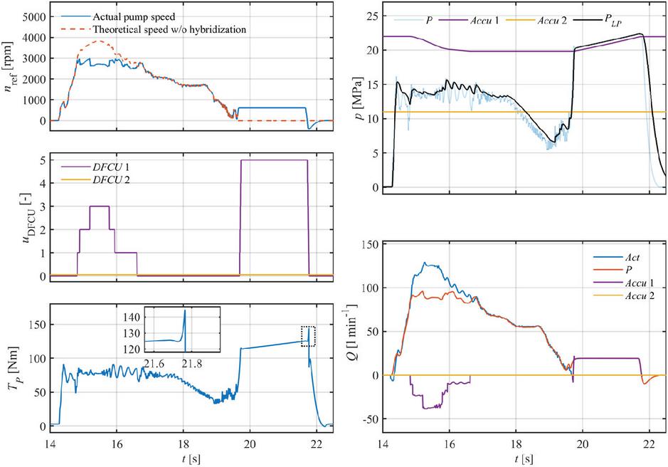
Figure 9 Excerpt presenting single discharging and charging period.
The close-up view of the load torque shows that the maximum output torque of the electric motor (132 Nm) is exceeded for 12 ms due to the static friction of the pump as the rotational speed approaches zero. In practice however, the electric motor is not required to deliver this transient excess torque, since bringing the pump to a stop is desired behaviour. Therefore, this transient peak is not considered in the sizing of the electric motor.
4.4 Comparison of Mean Power Losses
Energy losses of the three system architectures are summarized in Figure 10. The energy loss is given as mean power loss to aid in interpretation of the result.
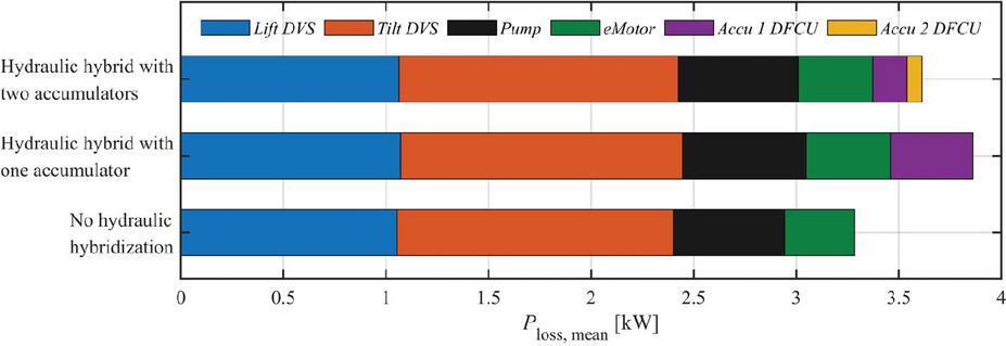
Figure 10 Comparison of mean power loss of the three system architectures studied.
To put the power loss numbers into perspective, the maximum output power of the electric motor in the two hydraulic hybrid cases is (3000 rpm, 132 Nm) 41 and 59 kW in the non-hybrid case (3000 rpm, 189 Nm). For example, the mean power losses of the non-hybrid case are approximately 6% of the maximum power of the prime mover.
4.5 Parametric Studies
Figure 11 summarizes the energy losses associated with various pressure settings of accumulator 2. The -axis is scaled to focus on the throttling losses related to the accumulator DFCUs. As shown, the throttling losses in the actuator DVSs remain virtually unaffected by the selected pressure of the second accumulator in this scenario. Furthermore, the pump and electric motor losses show only moderate variation across different pressure conditions, resulting in a maximum difference of no more than 3 kJ in the combined energy losses of the actuator DVSs, pump, and electric motor.
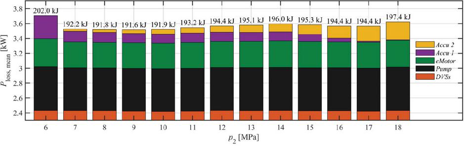
Figure 11 Energy and mean power loss as a function of accumulator 2 nominal pressure . Pump size is and the maximum torque of the motor is 132 Nm in each case studied.
The throttling losses of the accumulator DFCUs, in contrast, vary significantly depending on the pressure setting of the accumulator 2. When the pressure is relatively low, 14 MPa or less, the majority of the accumulator DFCU throttling losses originate from the accumulator 1 DFCU. Conversely, when the accumulator 2 pressure is 15 MPa or higher, most of the losses are associated with the DFCU of accumulator 2. It is evident that the extreme ends of the pressure range, 6 and 18 MPa, are poor choices, as they effectively behave like a single-accumulator system. Pressure settings between 7 and 17 MPa, however, result in varying total energy losses. The lowest energy loss is achieved by setting the accumulator 2 nominal pressure to 9 MPa in this case.
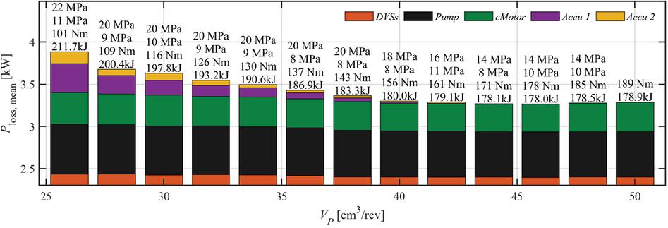
Figure 12 Energy and mean power loss as a function of the pump size. Text annotations from top: nominal pressure of accumulator 1 and 2, maximum torque of the electric motor, and energy losses.
Energy losses of the hydraulic hybrid can be further reduced by lowering the nominal pressure of accumulator 1, which was originally set to 22 MPa. The required pressure level of the high-pressure accumulator 1 depends on the pump size: the smaller the pump, the higher the accumulator 1 pressure must be to enable flow supplement against wider range of load pressures. Figure 12 presents a second parametric study, in which the pump size is varied. The accumulator 1 pressure is shown in the diagram, and it has been selected separately for each pump size according to the need. Only the smallest pump size considered, , requires accumulator 1 pressure of 22 MPa. Pump sizes require accumulator 1 pressure level of 20 MPa. When the pump size is further increased, the required pressure level drops fast. However, is limited to 14 MPa to ensure reasonable two-accumulator operation with sufficient pressure ranges.
The accumulator 2 nominal pressure is selected separately for each pump size such that the overall energy loss is minimized. To find the optimal accumulator 2 pressure, the nominal pressure is incremented in steps of 1 MPa, and the simulation is repeated for each value. The minimum pressure is constrained to 8 MPa, while the maximum pressure is limited to .
The largest pump size considered, , operates without requiring any support from the accumulators, as shown in the baseline results. As the pump size is decreased, the activity of the hydraulic energy storages, i.e. the accumulators, increase. This is reflected in a gradual increase in throttling losses associated with the accumulator DFCUs. However, pump sizes of result in slightly decreased overall energy losses, and even the configuration increases total energy losses by only 1%. The energy losses increase gradually as the pump size is further reduced towards , which is still capable of charging the accumulators during the short idle periods in the load cycle with the originally set charging flow rate. However, the smallest pump size studied, , requires higher charging flow rate, which leads to increased throttling losses in the accumulator DFCUs.
The maximum torque of the electric motor is also presented in the diagram for each configuration. The required torque decreases from 189 Nm to 101 Nm as the pump is downsized to the minimum value of .
4.6 Limitations
The simulated power losses depend on the loss models of the hydraulic pump and the electric motor. The loss models are fitted according to efficiency maps of real components and therefore provide a realistic representation of their performance. However, the resulting parameterization is specific to the selected components. Although identical loss models are used for both the baseline and the proposed hydraulic hybrid systems, the reported results are affected by the loss characteristics of the selected components.
The simulation results presented are based on measured data from a wheel loader performing a gravel-loading -cycle. Consequently, the results are specific to this machine type and work cycle. Although the -cycle represents a common wheel loader operation, actual machine usage can vary significantly depending on the application. Therefore, the quantitative results reported in this study cannot be directly generalized to other applications. While the proposed double-accumulator hydraulic hybrid concept is generally applicable to any mobile machine with valve-controlled hydraulic work functions, the achievable component downsizing potential and energy-efficiency are application dependent.
This study utilizes digital hydraulic valve control which offers fast dynamics and deterministic behaviour. While such systems require appropriate control strategies to mitigate undesirable flow and pressure transients, actuator controllability and motion smoothness are beyond the scope of the present work. These aspects are therefore left for future experimental investigation. Nevertheless, information on control resolution of digital hydraulic valve system and alternative modulation strategies can be found in [14].
5 Conclusions
Simulation study of hydraulic hybrid arrangement in electrified wheel loader application is presented, motivated by the potential to downsize the electric motor. The hydraulic hybrid configuration employs two hydraulic accumulators, each controlled by a DFCU. Although energy is discharged from the accumulators by means of throttling control, the added throttling losses remain moderate. The maximum torque requirement of the electric motor can be reduced by 17% with only 1% increase in total energy losses over the studied load cycle. Further reduction in electric motor capacity comes at the cost of increased energy losses. As an example, the electric motor can be downsized by 42% in this application, if approximately 12% increase in total energy loss is accepted.
The proposed solution transfers part of the electrical power demand to the hydraulic domain, enabling the use of a lower-rated and more cost-effective motor and inverter. While the accumulators require additional installation space, they can be integrated relatively freely within the machine. The achievable downsizing and associated energy losses are strongly dependent on the machine type and load cycle, making the application of this solution to other mobile machines an interesting topic for future research.
Acknowledgements
This work was supported by Business Finland’s Drive Forward project [grant number 428/31/2024]. Special thanks to Topi Mikkola and Maram Ahmad for their contributions to the development of the pump loss model and the electric motor loss model, respectively.
References
[1] A. Jansson and J. Palmberg, “Separate Controls of Meter-in and Meter-out Orifices in Mobile Hydraulic Systems,” SAE Technical Paper 901583, 1990.
[2] A. Shenouda, “Quasi-Static Hydraulic Control Systems and Energy Savings Potential Using Independent Metering Four-Valve Assembly Configuration,” Ph.D. dissertation, Woodruff School of Mechanical Engineering, Georgia Institute of Technology, 2006.
[3] M. Linjama, M. Huova, P. Boström, et al., “Design and implementation of energy saving digital hydraulic control system,” in The Tenth Scandinavian International Conference on Fluid Power, Tampere, Finland, May 21–23, 2007.
[4] K. Abuowda, I. Okhotnikov, S. Noroozi, et al., “A review of electrohydraulic independent metering technology,” ISA Transactions, vol. 98, pp. 364–381, 2020.
[5] X. Liu, “A Review of Potential Energy Recovery and Reutilization Technologies for Hydraulic-Driven Manipulators in Construction Machinery,” International Journal of Mechatronics and Applied Mechanics, 2025, no. 20, vol. 1.
[6] T. Jung, H. Raduenz, P. Krus, V. De Negri, and J. Lee, “Boom energy recuperation system and control strategy for hydraulic hybrid excavators,” Automation in Construction, vol. 135, p. 104046, 2022.
[7] P. Casoli, L. Riccò, F. Campanini, and A. Bedotti, “Hydraulic Hybrid Excavator – Mathematical Model Validation and Energy Analysis,” Energies, vol. 9, no. 12, p. 1002, 2016, doi: 10.3390/en9121002.
[8] M. Vukovic, R. Leifeld, and H. Murrenhoff, “STEAM – a hydraulic hybrid architecture for excavators,” in 10th International Fluid Power Conference, Dresden, Germany, 2016.
[9] R. Hippalgaonkar and M. Ivantysynova, “Optimal power management of hydraulic hybrid mobile machines – Part I: Theoretical studies, modeling and simulation,” Journal of Dynamic Systems, Measurement, and Control, vol. 138, no. 5, p. 051002, 2016.
[10] R. Hippalgaonkar and M. Ivantysynova, “Optimal power management of hydraulic hybrid mobile machines – Part II: Machine implementation and measurements,” Journal of Dynamic Systems, Measurement, and Control, vol. 138, no. 5, p. 051003, 2016.
[11] K. Einola and A. Kivi, “Hydraulic hybrid cut-to-length forest harvester – evaluation of effects on Productivity and Fuel Efficiency,” in Actuators, vol. 13, no. 4, p. 126, MDPI, 2024.
[12] M. Linjama, M. Huova, J. Tammisto, et al., “6-ton wheel loader short Y-cycle data for 440 seconds loading of gravel,” Zenodo, dataset, Feb. 9, 2024, doi: 10.5281/zenodo.10639199.
[13] M. Linjama and M. Huova, “Digital Hydraulic Control of Accumulator Flow in Hydraulic Hybrid,” in Workshop on Digital Fluid Power 2024, pp. 164–182, Tampere, Finland, 2024.
[14] M. Huova, “Digital hydraulic work functions of a prototype wheel loader,” in The Twelfth Workshop on Digital Fluid Power, Tampere, Finland, June 6–7, 2024.
[15] A. Ellman and R. Piche, “Modified orifice flow formula for numerical simulation of fluid power systems,” in ASME Fluid Power Systems and Technology (FPST), vol. 3, pp. 59–63, 1996.
[16] M. Huova, J. Tammisto, M. Linjama, et al., “Fuel Efficiency Analysis of Selected Hydraulic Hybrids in a Wheel Loader Application,” in Symposium on Fluid Power and Motion Control (FPMC), Bath, U.K., Sept. 12–14, 2018.
[17] Innas B.V., “Performance of Hydrostatic Machines,” Breda, Netherlands, June 8, 2020. [Online]. Available: https://www.innas.com/assets/performance-of-hydrostatic-machines.pdf, [Accessed: Aug. 14, 2025].
[18] Engiro, “ENGIRO_Datasheet_205W_12023_P_ABC_V002.pdf.” [Online]. Available: https://www.engiro.com/products/motors-and-generators, [Accessed: Aug. 27, 2025].
[19] A. Aroua, W. Lhomme, F. Verbelen, et al., “Impact of scaling laws of permanent magnet synchronous machines on the accuracy of energy consumption computation of electric vehicles,” eTransportation, vol. 18, p. 100269, 2023.
Biography

Mikko Huova received his MSc in automation engineering in 2008 and completed his PhD in the same field in 2015, both from Tampere University of Technology. He is currently working as a senior research fellow at the Automation Technology and Mechanical Engineering unit at Tampere University. His areas of interest include energy efficient actuator systems, mobile machinery and model-based control.
International Journal of Fluid Power, Vol. 27_3, 649–649
doi: 10.13052/ijfp1439-9776.2737
© 2026 River Publishers