Manipulation Strategy of Vortex Cavitation Evolution in Poppet Valves Through Structure Modification
Cong Yuan
College of Mechanical and Automotive Engineering, Zhaoqing University, Zhaoqing City, Guangdong Province, People’s Republic of China
E-mail: william.yuan.c@gmail.com
Received 06 December 2025; Accepted 19 August 2026
Abstract
Owing to the extreme operating conditions experienced by poppet valves, cavitation occurs frequently and unavoidably. This study investigates manipulation strategies for vortex cavitation throughout its evolutionary process within poppet valves featuring a sharp valve seat. The flow dynamics of the cavitating jet are elucidated via a series of numerical simulations. Cavitation is found to occur mainly in three distinct regions: free-shearing vortex cavitation, wall-shearing vortex cavitation, and attached cavitation at the poppet trailing edge. The formation mechanisms of these three cavitation types are further revealed based on the corresponding flow dynamics. The cyclic behavior of cavitation structures identifies two key interactions during the transient evolution of the cavitating jet, which are the merging of free-shearing and wall-shearing vortex cavitation, and the secondary growth of vortex cavitation accompanied by entrainment of attached cavitation. Through detailed analysis of cavitation intensity variations under different valve openings, it is shown that the development of free-shearing vortex cavitation is primarily governed by the intensity and thickness of the shear layer, whereas wall-shearing cavitation is additionally influenced by the jet potential core thickness, and attached cavitation is controlled by the local velocity gradient. Guided by the identified cavitation dynamics mechanisms, manipulation strategies through structural modification are proposed to suppress the developmental growth of each cavitation form. Finally, a complementary numerical investigation validates the effectiveness of the proposed manipulation strategies and the modified geometry in mitigating overall cavitation intensity.
Keywords: Vortex cavitation, cavitation manipulation, poppet valve, cavitation evolution.
1 Introduction
Poppet valves are widely employed in hydraulic transmission systems, predominantly serving as pressure regulators and in the pilot stages of composite control components. When used as pressure regulators, a poppet valve is designed to operate under a large pressure difference, giving rise to high susceptibility to cavitation. A growing body of research indicates that cavitation is a common and nearly unavoidable phenomenon within poppet valves under typical pressure-regulator operating conditions. Furthermore, intense cavitation induces a series of detrimental effects, including pressure pulsations that degrade operational performance, as well as cavitation erosion that poses a serious risk of component failure. Consequently, the cavitation issue has attracted considerable research attention in the field of hydraulic valves.
A large part of the studies, particularly in the earlier years, were mainly concentrated on the quantification of cavitation effects. Oshima and Ichikawa [1–3] performed a visual observation of the cavitation phenomenon inside poppet valves, and made efforts to quantify the cavitation effects, covering the flow choking phenomenon, thrust force characteristics. Oshima et al. [4] reported the cavitation morphology inside water poppet valves with varied valve seat structure, and explained the variation in the flow discharge curve due to the development of cavitation using pressure distribution. Washio et al. [5] measured the flow performance of poppet valves with difference back pressure, and proposed a compensation for the cavitation effect. Yi et al. [6] investigated the noise level of poppet valves under cavitating and non-cavitating conditions, and unraveled the interaction between poppet vibration and cavitation dynamics. Cavallo et al. [7] proposed a visualization apparatus for cavitation phenomenon inside poppet valves and provided full insight in both inception and the spatial development of cavitation. Han et al. [8] performed a numerical study on cavitation flow dynamics of poppet valves, and generalized the influence of cavitation on thrust flow characteristics.
Recent advances in experimental and computational techniques have motivated extensive investigations into the cavitation mechanisms occurring in poppet valves. Using flow visualization experiments and numerical simulations of internal flow structures, Ueno et al. [9] identified the strong correlation between cavitation patterns and large-scale recirculating flow structures. Washio et al. [5] captured the cavitation nucleation process using high-speed imaging and identified flow separation as a key precursor to cavitation inception in poppet valves. Yuan et al. [10] conducted numerical analyses of the cavitating jet dynamics within poppet valves and revealed the formation of paired vortex cavitation structures and their dependence on vortex evolution. In a subsequent study, Yuan et al. [11] examined the evolution of coherent flow structures in poppet valves and highlighted their close coupling with the global jet flow state. Lu et al. [12] performed numerical simulations of cavitating flow in poppet valves and found that persistent cavitation structures within valve grooves can induce choked flow conditions. Wei et al. [13] numerically investigated shear-induced cavitation in conical poppet valves and determined that the second-order time derivative of cavitation volume dominates internal pressure pulsations. Notably, these studies collectively confirm that computational fluid dynamics (CFD) approaches are capable of resolving unsteady cavitation structures, capturing vortex evolution, and reproducing key dynamic features of cavitating flow fields. This body of literature validates the suitability of CFD for analyzing the complex, unsteady characteristics of cavitating flows in poppet valves, thereby providing a reliable foundation for the present numerical investigation.
Another concern on cavitation through poppet valves refers to cavitation suppression. Based on the experimental observation and simulation results, Ueno et al. [9] pointed out that the presence of a large downstream chamber contributes to the establishment of a tremendous circulation flow and facilitates the suppression of cavitation. Liu et al. [14] investigated the cavitation characteristics of poppet valves with different valve seat structure, and confirmed the delayed effect of a two-stage valve seat structure in cavitation inception. Gao et al. [15] investigated the cavitation distribution inside poppet valves and proposed the advantage of reducing outlet area in suppression of cavitation inception. Liu et al. [16] compared the flow dynamics inside poppet valves with different valve seat structure, and proved the superior suppression ability of cavitation inception of the twostage valve seat due to the smaller pressure drop. Liu et al. [17] investigated the influence of structural parameters on the two-stage poppet valve, and derived the design criterion pertaining to cavitation inception suppression. Nie et al. [18] studied the pressure distribution inside poppet valves with varying valve seat structure via numerical simulation, and derived the design criterion in terms of optimum pressure distribution to suppress cavitation inception.
The aforementioned studies contribute to a comprehensive understanding of the cavitation characteristics inside poppet valves. However, two issues remain unresolved. The first issue identified from these studies is that most of the proposed cavitation suppression methods focus on the cavitation inception stage, aiming at the complete elimination of cavitation. However, the occurrence of cavitation appears to be inevitable in poppet valves, particularly when they are used as the main stage of pilot-operated pressure relief valves. The second issue has gradually emerged with the clarification of the underlying mechanism of vortex cavitation in previous studies. Vortex cavitation, which plays a significant role in the cavitating flow through poppet valves, has rarely been considered in previous studies on structural optimization for cavitation suppression.
The aforementioned two issues inspire the current study, which is targeted at manipulating the evolution of vortex cavitation, since cavitation could not be completely eliminated under typical operating conditions. Additionally, the comprehensive understanding on vortex cavitation inside poppet valves achieved from prior studies not only gives an explanation for the correlated flow physics, but also serves as the theoretical basis for manipulation of vortex cavitation through control of its evolution and interaction with other flow instabilities. The current study assumes the investigation strategy as below. First, the vortex cavitation is examined in terms of morphology and distribution via a numerical simulation. Secondly, the dynamic behavior associated with the evolution of vortex cavitation is inspected separately, in order to reveal the underlying mechanism. Finally, several manipulation strategies are proposed based on the governing mechanism of the vortex cavitation evolution. The generalized manipulation strategies lead to structural modification of the original poppet valve structure, which exhibits tremendous potential in lowering cavitation intensity during the evolution process after inception according to a validation study.
2 Mathematical Model
The volume of fluid (VOF) algorithm is utilized to simulate the two-phase flow. The compressibility of each phase is included, and only one phase transport equation is involved in the scenario of two-phase flow, expressed as
| (1) |
is defined as the relative velocity between the two phases
| (2) |
In the VOF algorithm, the momentum conservation equation comprises an extra term corresponding to the surface tension effect
| (3) |
where, the curvature of interface is expressed as a function of vapor fraction gradient
| (4) |
The Poisson pressure equation could be derived utilizing the mass conservation equation
| (5) |
The detailed derivation of Equations (1)–(5) can be found in a previous study [19].
And the cavitation and condensation terms are simulated by introducing the Sauer–Schnerr cavitation model [20]
| (6) |
Actually, the current study is mainly concerned on fully developed cavitation rather than cavitation inception. in such a case, the gaseous content in mineral oil plays a marginal role for the cavitation development, particularly the later process after inception. Even though, in some cavitation model [21], the gaseous content is compensated with increased cavitation threshold pressure, but such compensation could be negligible for the current fully developed cavitation with significantly high ambient pressure. Therefore, the current simulation excludes the gaseous content.
The other variables in the foregoing mathematical model are interpreted by Table 1, and the subscripts and designate liquid and vapor phase, respectively. Based on the mathematical model, a numerical method incorporating the PIMPLE loop is established on OpenFOAM. In the numerical method, the phase transport equation is solved with the explicit MULES algorithm, while the pressure equation is calculated with the PISO algorithm.
Table 1 Definition of variables
| Variable | Definition |
| Volume fraction | |
| Density | |
| Compressibility constant | |
| Cavitation model constant | |
| Artificial compression coefficient | |
| Surface tension coefficient | |
| Source term due to inter-phase change | |
| Cavitation threshold pressure | |
| Local stress tensor |
3 Calculation Configuration
The fluid domain considered in the current numerical study includes a sector with 45∘, and the corresponding mesh model is demonstrated as Figure 1, which includes 4,300,000 to 7,400,000 cells depending on the valve opening. The inlet and outlet are specified as fixed pressure boundary condition, the two sides are set as symmetry. And the other boundaries are walls. The inlet boundary is positioned approximately 33 mm upstream of the valve seat, whereas the outlet boundary is located 46 mm downstream of the valve seat. The fluid properties of used mineral oil is provided in Table 2.
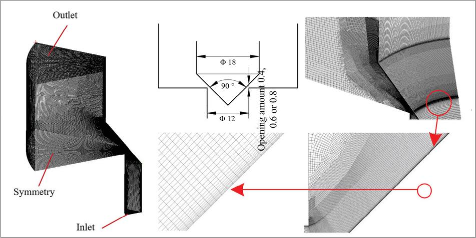
Figure 1 Calculation domain of the considered poppet valves and the details of mesh model (dimension in mm).
Table 2 Fluid property
| Liquid Type | Mineral Oil #46 |
| Liquid density | 872 kg m-3 |
| Liquid dynamic viscosity | 0.042 N s m-2 |
| Vapor pressure | 3000 pa |
| Vapor density | 0.13 kg m-3 |
| Vapor dynamic viscosity | 0.00572 N s m-2 |
| Temperature | 313K |
| Surface tension | 0.03 N m-1 |
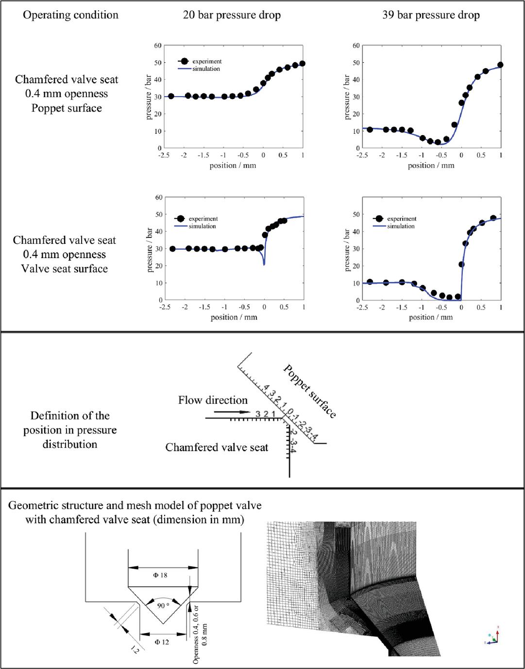
Figure 2 Comparison between calculation results and experimental measurement in terms of timeaverage pressure on the poppet surface and the valve seat surface.
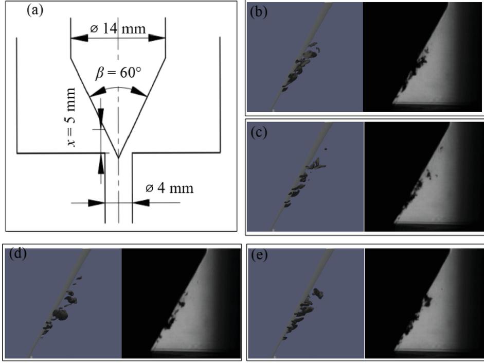
Figure 3 Comparison between calculation results and experimental measurement in terms of instantaneous cavitation morphology. (a) valve structure; (b, c) comparison between experiment and simulation for operation condition of 5 bar outlet pressure and 51 bar inlet pressure; (d, e) comparison between experiment and simulation for operation condition of 5 bar outlet pressure and 46 bar inlet pressure.
The numerical method is validated first through a case study on a poppet valve with chamfered valve seat, which is a bit different from the targeted poppet valve in the current study. Figure 2 provides the comparison between the simulation result and experimental measurement from a previous study [22]. The validation study involves cavitating and non-cavitating cases. The numerical prediction generally agrees well with the measured data except on the chamfered valve seat in the non-cavitating case, where the numerical prediction gives a much stronger pressure drop than the measurement. Such a deviation is essentially due to that the inlet corner of the chamfered groove inevitably assumes a minor rounding feature, which serves as an efficient role in suppressing the local pressure drop and could not be sensibly compensated in the simulation. In the cavitating cases, a sufficiently sudden pressure drop occurs to the chamfered valve seat, indicating the presence of the cavitating region. In comparison, the pressure distribution on the poppet surface exhibits a mild reduction. Such a pressure distribution characteristic is essentially reproduced by the numerical method, indicating the validity of the applied numerical method.
The second validation case focuses on cavitation morphology and includes two cavitating conditions with pressure drops of 41 and 46 bar, respectively. The cavitation images were captured with an exposure time of 2 s, enabling the observation of the instantaneous characteristics of the cavitation structures. The poppet valve used in the experiment has a poppet angle of 60∘ and an opening of 0.5 mm, as shown in Figure 3(a). The fluid properties remain the same as those described previously. The detailed experimental configuration can be found in the previous study [10]. As shown in the experimental images, cavitation gradually develops along the divergent jet flow originating from the annular clearance. The cavitation structures exhibit an intermittent pattern rather than a continuous one. In general, cavitation collapses approximately in the middle region between the valve seat and the poppet end. These features are well reproduced by the simulation results.
4 Results and Discussion
4.1 Cavitation Morphology and Triggering Mechanism
Figure 4 presents the simulation results for three cases of different valve openings, including instantaneous velocity contour, instantaneous vapor content contour, 3D view of cavitation morphology, and vortex structure imposed on instantaneous cavitation morphology. The cavitation follows a quite similar distribution pattern irrelevant of the variation in valve opening, according to the time-average vapor content contour. In general, the occurrence of cavitation is concentrated in three regions, comprising the freeshearing layer, the wall-shearing layer, and the downstream of poppet trailing edge. The cavitation at these three regions is individually examined subsequently.
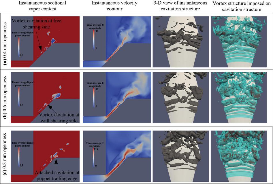
Figure 4 Calculation results for poppet valves with varying valve opening. (The blue-colored vortex structure is visualized by , while the gray cavitation structure is identified with .) Operating condition is 6 bar outlet pressure and 51 bar inlet pressure.
According to the instantaneous vortex structure in Figure 4, a large-scale vortex structure is developed gradually along the streamwise direction of the jet potential core. And the vortex structure is delicately located at the two sides of the jet potential core. Furthermore, the instantaneous cavitation at the two sides of the jet potential core is not only located persistently within the vortex core, but also exhibits a morphology consistent with the instantaneous vortex structures. Such a strong correlation between the vortex structures and cavitation provides convincing evidence that the cavitation on the free-shear side and the wall-shear side is induced by the vortex structures. According to the instantaneous velocity contours, flow separation occurs at the poppet trailing edge, which agrees well with the cavitation observed downstream of the poppet trailing edge.
As a conclusion, the cavitation distribution is generally unchanged for the three cases with varying valve openings, and the triggering mechanisms for the three cavitation regions also remain the same.
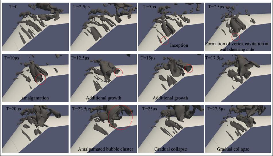
Figure 5 Cyclic process of cavitation behavior for the poppet valve with a 0.4 mm valve opening. (Cavitation structure is identified with .) Operating condition is 6 bar outlet pressure and 51 bar inlet pressure.
4.2 Cavitation Evolution Process and Relevant Mechanisms
Figures 5 and 6 exhibit the cyclic behavior of cavitation inside poppet valves of 0.4 and 0.6 mm valve openings, which mainly includes five stages. Each of the five stages is featured with a characteristic behavior, the inception of cavitation within the free-shearing layer, the formation of cavitation at the wall-shearing layer, the amalgamation between the vortex cavitation at the two sides of the jet potential core, the secondary growth of amalgamated vortex cavitation across the poppet trailing edge, and the gradual collapse. Since the current study is mainly concerned with the manipulation of cavitation evolution, the underlying mechanisms of several critical unsteady behaviors are examined separately in the following discussion.
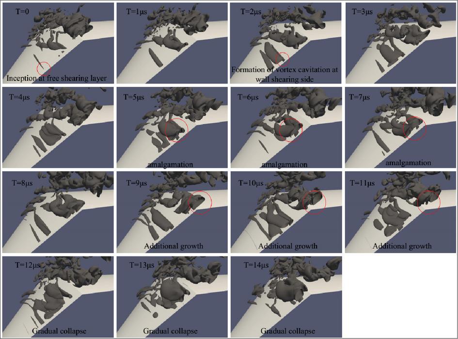
Figure 6 Cyclic process of cavitation behavior for the poppet valve with a 0.6 mm valve opening. (Cavitation structure is identified with .) Operating condition is 6 bar outlet pressure and 51 bar inlet pressure.
(1) Free-shearing vortex cavitation
As mentioned above, the inception of vortex cavitation on the free-shear side is attributed to vortex dynamics. Subsequently, the cavity size increases with the development of the vortex structures, followed by its amalgamation with the vortex cavitation on the wall-shear side upstream of the poppet trailing edge. It is also observed that cavitation on the free-shear side is intensified with increasing valve opening, as shown in Figure 7. Figure 8 presents the time-averaged velocity contours as well as the corresponding profiles along the black lines, which exhibit comparable velocity gradients on the free-shear side of the jet potential core for the three cases with different valve openings. However, the thickness of the free-shear layer increases significantly with increasing valve opening. Since vortex growth is driven by the stretching of the shear layer, the increased shear layer thickness promotes the formation of stronger vortex structures, thereby enhancing the associated cavitation.
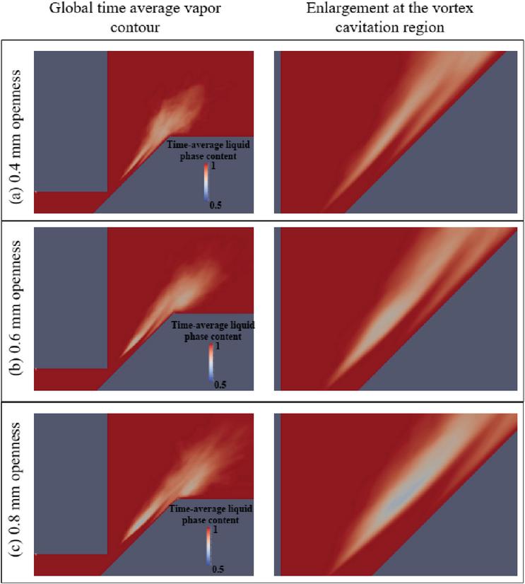
Figure 7 Time-average vapor contour. Operating condition is 6 bar outlet pressure and 51 bar inlet pressure.
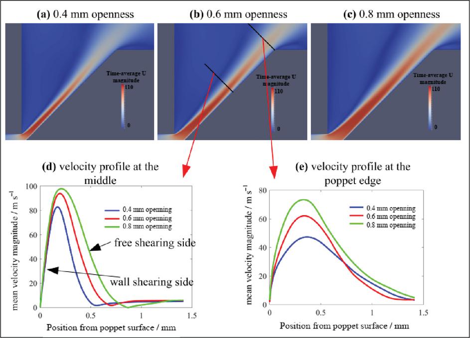
Figure 8 Time-average velocity contour and velocity profile of the jet potential core at two different streamwise positions. Operating condition is 6 bar outlet pressure and 51 bar inlet pressure.
(2) Wall-shearing vortex cavitation
The wall-shearing-side cavitation is initiated by a mechanism similar to that of the free-shearing-side cavitation and follows a comparable evolution process. However, as shown in Figure 7, the wall-shearing-side cavitation becomes slightly weaker with increasing valve opening, and its inception is shifted downstream. According to Figure 8, both the wall-shear intensity and the thickness of the shear layer increase with increasing valve opening, which appears to contradict the behavior observed for free-shearing-side cavitation.
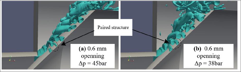
Figure 9 Establishment of paired vortex structure at varying operating conditions. (The vortex structure colored blue is identified with .) Operating condition is 6 bar outlet pressure and 51 bar inlet pressure.
Figure 9 presents the vortex structures under different operating conditions. A common and distinctive flow feature is the formation of a paired vortex structure consisting of vortices on the free-shearing side and the wall-shearing side. This indicates a strong interaction between the two vortices, which is responsible for the wavy pattern and the local flow separation of the jet potential core observed in the instantaneous velocity contours in Figure 4, as reported previously [10].
Figure 10 shows the time-averaged liquid fraction distribution, revealing that the wall-shearing-side cavitation is noticeably deferred relative to the free-shearing side, rather than coinciding with the peak velocity gradient. This deviation between vapor distribution and wall-shear intensity highlights the non-negligible influence of interactions with the freeshearing-side vortex. Although the increased valve opening enhances the wall-shear intensity, which is generally favorable for vortex development, Figure 8 also indicates a thickening of the jet potential core. Therefore, it is reasonable to conclude that the weakening of wall-shearing-side cavitation at a larger valve opening is primarily due to the increased thickness of the jet potential core.
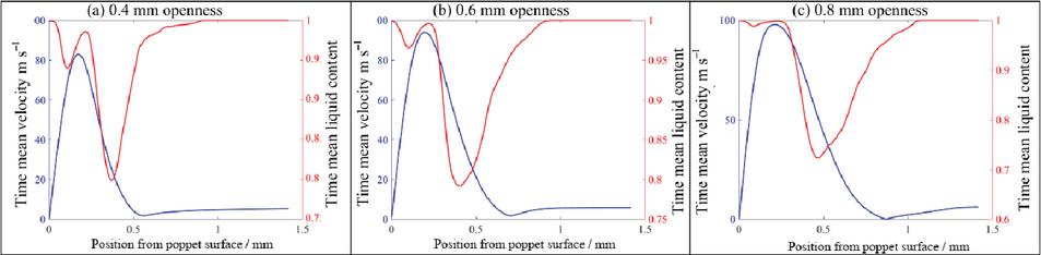
Figure 10 Comparison between time mean velocity and vapor content profile at the middle black line in Figure 8(b).
(3) Attached cavitation at the poppet trailing edge
The amalgamation of vortex cavitation at the two sides of the jet potential core gives rise to cavitating vortex lumps with significant size, which experiences sequentially a secondary growth across the poppet trailing edge and a gradual collapse thereafter. The secondary growth is due to the flow separation at the poppet trailing edge, contributing to flow instabilities in the form of a detached vortex or cavitation depending on the valve opening. The detailed process of the secondary growth is illustrated in Figure 11. Due to the entrainment effect of the passing cavitating vortex lumps, the flow instabilities at the poppet trailing edge undergo a detachment prior to their complete independent development. Afterwards, the detached flow instabilities are entrapped into the vortex lumps, contributing to the secondary growth. According to Figure 7, the cavitation region beyond the poppet trailing edge amplifies with increased valve opening. Figure 8(e) presents the time-average velocity profile corresponding to the black line at the poppet trailing edge in Figure 8(b), which indicates the increased shearing intensity with a larger valve opening. The increased shearing intensity facilitates the generation of flow instabilities, and thus contributes to stronger secondary growth of the passing cavitating vortex lumps. As shown in the enlarged view at the poppet trailing edge of Figure 12, the cavitation region is elevated in terms of size and intensity, and also deferred towards the poppet surface.
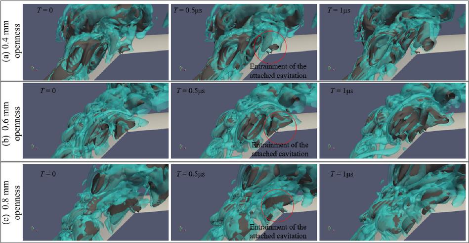
Figure 11 Detailed process of secondary growth at the poppet trailing edge. Operating condition is 6 bar outlet pressure and 51 bar inlet pressure.
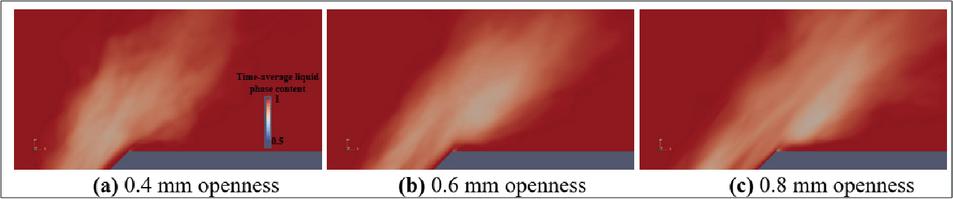
Figure 12 Enlarged view of time mean vapor content at the poppet trailing edge. Operating condition is 6 bar outlet pressure and 51 bar inlet pressure.
4.3 Manipulation Strategy of Vortex Cavitation Evolution and Validation
Based on the unsteady behavior and the underlying mechanisms, targeted manipulation strategies for cavitation evolution are proposed for each specific type of cavitation. For cavitation occurring in the free-shear layer, which is highly sensitive to shear intensity, the effective strategy is to weaken the velocity gradient within the shortest possible transit distance. As the cone poppet induces a gradually diverging flow, increasing the poppet angle or reducing the nozzle diameter enhances the divergence of the jet potential core. However, it should be noted that an excessively large poppet angle may generate a persistent large-scale recirculating flow within the chamber, which in turn promotes additional vortex cavitation [9].
For vortex cavitation on the wall-shearing side, which is closely related to the thickness of the jet potential core, adopting a relatively large valve opening under the designed operating condition is an effective strategy, as it increases the core thickness and reduces shear intensity near the wall.
Regarding the secondary growth of cavitation at the poppet trailing edge, which is sensitive to near-wall-shear intensity, the effective strategy is to weaken the near-wall velocity gradient. This can be achieved either by reducing the valve opening or by increasing the flow divergence near the trailing edge, both of which help attenuate the wall-shearing effect. In addition, extending the cone section of the poppet provides a longer transit distance, allowing sufficient dissipation of cavitating vortex structures before they reach the trailing edge, thereby suppressing secondary growth.

Figure 13 Validation case of cavitation manipulation strategy for varied poppet cylinder diameter. Operating condition is 6 bar outlet pressure and 51 bar inlet pressure.
Based on the above analysis, both increased flow divergence and an extended cone poppet length contribute significantly to cavitation suppression. Therefore, a series of targeted validation studies are conducted in the following section. In these validation cases, the poppet angle is fixed at 45∘, and comparisons are performed under identical opening conditions.
In the first validation, the nozzle diameter is fixed at 8 mm, while the poppet cylinder diameter is changed within 12, 15, 18, 24 mm. Figure 13 exhibits the time-average distribution of vapor content. For the case of 12 mm, the transported vortex cavitation still experiences a gradual expansion, while the jet flow arrives at the poppet trailing edge point. On one hand, attached cavitation is triggered at the trailing edge point due to the flow circulation. On the other hand, the wall side vortex cavitation entrained the attached vortex cavitation. As a sequence, the time-average cavitation content is up to 45% at the wake region, equivalent to the highest level of shearing side vortex cavitation. For the case of 15 mm, the cavitation content at the downstream of the poppet trailing edge has an evident reduction in vapor content, but the cavitation region expanded at the wake, comparing to the reference 12 mm case. For the case of 18 and 24 mm, the attached cavitation is negligible, and the secondary growth of the vortex cavitation is essentially suppressed. Even though the cavitation covers a large region at downstream, but the vapor content is reduced. It indicates a continuously dissipation. The time-average total content is reduced by over 9% for cases 18 and 24 mm, compared to the reference 12 mm case.
In the second validation case, the poppet cylinder diameter is fixed at 30 mm, while the nozzle diameter is varied across 3, 6, 9, and 12 mm. Figure 14 shows the time-averaged distribution of vapor content. As the nozzle diameter decreases, vortex cavitation shows a clear reduction in both layer thickness and vapor volume fraction. The cavitation region in the wake also shrinks noticeably. Overall, the total vapor volume, which is normalized by the effective cross-sectional area to account for variations in nozzle diameter, decreases significantly. In particular, the compensated total vapor volume for the 3 mm nozzle is approximately 16% lower than that of the reference 12 mm case.
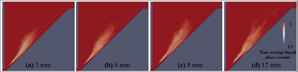
Figure 14 Validation case of cavitation manipulation strategy for varied nozzle diameter. Operating condition is 6 bar outlet pressure and 51 bar inlet pressure.
An additional numerical case is established to validate the proposed control strategies under varying valve openings. As depicted in Figure 15, the geometric configuration of this case incorporates several modifications based on the proposed strategies, including a contracted nozzle with a diameter of 3 mm and poppet cylinder diameter of 13 mm. This design promotes sufficient dissipation of vortex structures before their arrival at the trailing edge. The original poppet valve geometry shown in Figure 1 is employed as the reference configuration. Two operating conditions with valve openings of 0.6 and 0.8 mm are investigated to allow a comprehensive analysis of the interactions between different cavitation patterns.
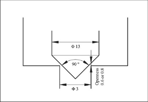
Figure 15 Geometric structure of the proposed modification (dimension in mm).
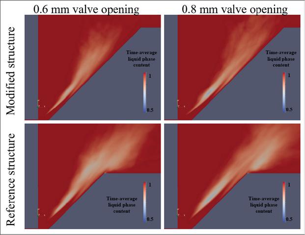
Figure 16 Results of the validation study case in terms of time-mean vapor distribution with a comparison to the original structure. Operating condition is 6 bar outlet pressure and 51 bar inlet pressure.
Figure 16 presents the simulation results for this case. The effectiveness of the cavitation control strategy is verified through the following key characteristics of the cavitating flow. First, secondary cavitation growth at the poppet trailing edge is entirely eliminated by the modified geometry. Second, cavitation on the free-shearing side is visibly reduced under both opening conditions. Third, the vortex lumps formed by the merging of wall-shearing-side and free-shearing-side vortex cavitation are also substantially attenuated and fully dissipated before reaching the poppet trailing edge. Fourth, cavitation downstream of the trailing edge is completely suppressed, although minor residual flow instabilities remain.
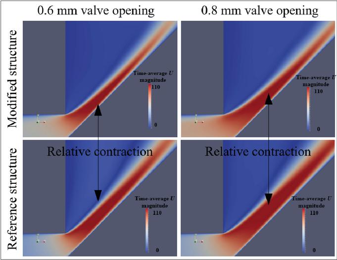
Figure 17 Results of the validation study case in terms of time-mean velocity distribution with a comparison to the original structure. Operating condition is 6 bar outlet pressure and 51 bar inlet pressure.
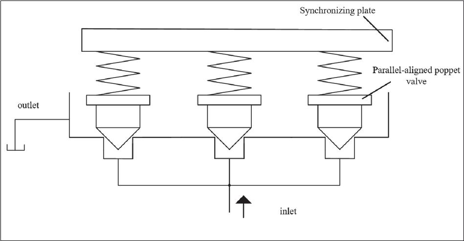
Figure 18 Illustration of pressure regulators with parallel configuration.
Noticeably, the inception of vortex cavitation at the free-shearing side shifts slightly towards to annular clearance for both valve opening conditions in Figure 16. Such a phenomenon is due to the contraction of jet potential core at the immediate downstream of annular clearance with a stronger diverging trend in the modified structure, which tends to intensify the local shearing effect, as shown in Figure 17. Even though the cavitation inception is accelerated in the modified structure, the general cavitation intensity as well as cavitation region is preferentially reduced, indicating the efficiency of the manipulation strategy. Considering that the cross-section of the annular clearance in the modified structure accounts for only approximately 1/4 of the original structure, a simple alternative with a parallel configuration could achieve a sufficiently large cross-section while retaining the advantage of cavitation suppression, as shown in Figure 18.
5 Conclusion
Based on numerical investigations, the three types of cavitation within a poppet valve are comprehensively analyzed in terms of cavitation morphology, evolutionary behavior, and underlying mechanisms. Corresponding control strategies are proposed according to the evolutionary characteristics of each cavitation form, and their effectiveness is further verified through systematic case studies. The main conclusions are summarized as follows:
(1) Vortex cavitation on the free-shearing side is sensitive to shear intensity. A stronger flow divergence tendency weakens the free-shearing intensity, thereby suppressing the development of vortex cavitation.
(2) The vortex cavitation at the wall-shearing side involves a correlation with the freeshearing-side vortex, and exhibits sensitivity to the jet potential core thickness.
(3) Attached cavitation at the poppet trailing edge, induced by flow separation and sensitive to near-wall-shear intensity, promotes the secondary growth of advected cavitating vortex lumps. Extending the conical section of the poppet reduces near-wall-shear intensity and enables complete dissipation of vortex lumps over the conical surface, thus effectively eliminating cavitation downstream of the poppet trailing edge.
Acknowledgement
We are grateful for financial support from Guangdong Provincial Characteristic Innovation Project for Higher Education Institutions (No. 2025TSCX1075), Zhaoqing University High-Level Talent Development Program Project (No. gcc202513), Key Research Project of Zhaoqing University (No. ZD202405), Natural Science Foundation of Guangdong Province (No. 2024A1515011408), Guangdong Provincial Key Area Research Project for Higher Education Institutions (No. 2022ZDZX3035).
Data Availability Statement
Part of the datasets generated and/or analyzed during the current study are available from the corresponding author upon reasonable request. Publicly accessible datasets used in this study are cited in the article, and their sources are as follows:
[1] 袁聪.倒角式水压锥阀空化流场动态模拟计算结果 [EB/OL]. [2024-05-30]. https://pan.baidu.com/s/1C6IXtHVtZ6uOabfIFOR9Ng. (提取码/password: 1234). For proprietary or confidential data not publicly available, access can be requested from the corresponding author under specific conditions due to data privacy and confidentiality agreements.
Disclosure Statement
No potential conflict of interest was reported by the authors.
References
[1] S. Oshima and T. Ichikawa, “Cavitation phenomena and performance of oil hydraulic poppet valve: 1st report – mechanism of generation of cavitation and flow performance,” Bulletin of the JSME, vol. 28, no. 244, pp. 2264–2271, 1985.
[2] S. Oshima and T. Ichikawa, “Cavitation phenomena and performance of oil hydraulic poppet valve: 2nd report – influence of the chamfer length of the seat and the flow performance,” Bulletin of the JSME, vol. 28, no. 244, pp. 2272–2279, 1985.
[3] S. Oshima and T. Ichikawa, “Cavitation phenomena and performance of oil hydraulic poppet valve: 5th report – influence of dimensions of valve on the thrust force characteristics,” Bulletin of the JSME, vol. 29, no. 251, pp. 1427–1433, 1986.
[4] S. Oshima, T. Leino, M. Linjama, K. T. Koskinen, and M. J. Vilenius, “Effect of cavitation in water hydraulic poppet valves,” International Journal of Fluid Power, vol. 2, no. 3, pp. 5–13, 2001.
[5] S. Washio, S. Kikui, and S. Takahashi, “Nucleation and subsequent cavitation in a hydraulic oil poppet valve,” Proceedings of the Institution of Mechanical Engineers, Part C: Journal of Mechanical Engineering Science, vol. 224, no. 4, pp. 947–958, 2010.
[6] D. Yi, L. Lu, J. Zou, and X. Fu, “Interactions between poppet vibration and cavitation in relief valve,” Proceedings of the Institution of Mechanical Engineers, Part C: Journal of Mechanical Engineering Science, vol. 229, no. 8, pp. 1447–1461, 2015.
[7] D. M. Cavallo, O. Chiavola, E. Frattini, and F. Palmieri, “A novel approach for hydraulic valve experimental assessment under cavitating condition,” International Journal of Fluid Power, pp. 183–204, 2022.
[8] M. Han, Y. Liu, D. Wu, X. Zhao, and H. Tan, “A numerical investigation in characteristics of flow force under cavitation state inside the water hydraulic poppet valves,” International Journal of Heat and Mass Transfer, vol. 111, pp. 1–16, 2017.
[9] H. Ueno, A. Okajima, and Y. Muromiya, “Visualization of cavitating flow and numerical simulation of flow in a poppet valve,” in Proc. JFPS Int. Symp. on Fluid Power, pp. 385–390, 1993.
[10] C. Yuan, Y. Cai, S. Liu, and Z. Du, “Simulation of cavitating jet through a poppet valve with special emphasis on laminar–turbulent transition,” International Journal of Fluid Power, pp. 27–58, 2020.
[11] C. Yuan, J. Song, and M. Liu, “Coherent structure of paired vortex and transition in flow pattern in cavitating jet through a poppet valve,” International Journal of Mechanical Sciences, vol. 152, pp. 19–33, 2019.
[12] L. Liang, Z. Liang, Y. Liu et al., “Geometrical transition properties of vortex cavitation and associated flow-choking characteristics in poppet valves,” Journal of Zhejiang University SCIENCE A, vol. 2024, no. 6, pp. 1–15, 2024.
[13] S. Wei, C. Lin, and B. Ji, “Large eddy simulation of cavitating flow in a cone valve with special emphasis on the shear cavitation inside and its effects,” Journal of Hydrodynamics, vol. 37, no. 5, pp. 876–891, 2025, doi: 10.1007/s42241-025-0072-8.
[14] Y. S. Liu, Y. Huang, and Z. Y. Li, “Experimental investigation of flow and cavitation characteristics of a two-step throttle in water hydraulic valves,” Proceedings of the Institution of Mechanical Engineers, Part A: Journal of Power and Energy, vol. 216, no. 1, pp. 105–111, 2002.
[15] H. Gao, W. Lin, and T. Tsukiji, “Investigation of cavitation near the orifice of hydraulic valves,” Proceedings of the Institution of Mechanical Engineers, Part G: Journal of Aerospace Engineering, vol. 220, no. 4, pp. 253–265, 2006.
[16] Y. Liu, Y. Yousheng, and Z. Zhuangyun, “Research on the flow and cavitation characteristics of multi-stage throttle in water-hydraulics,” Proceedings of the Institution of Mechanical Engineers, Part E: Journal of Process Mechanical Engineering, vol. 220, no. 2, pp. 99–108, 2006.
[17] X. Liu, J. He, Z. Long, W. Li, and B. Li, “Effects of structural sizes on characteristics of cavitating flows in a two-step throttle valve,” Journal of Vibration and Shock, vol. 34, no. 23, pp. 143–148, 2015.
[18] S. Nie, G. Huang, Y. Li, Y. Yang, and Y. Zhu, “Research on low cavitation in water hydraulic two-stage throttle poppet valve,” Proceedings of the Institution of Mechanical Engineers, Part E: Journal of Process Mechanical Engineering, vol. 220, no. 3, pp. 167–179, 2006.
[19] C. Yuan, J. Song, and M. Liu, “Investigation of flow dynamics and governing mechanism of choked flow for cavitating jet in a poppet valve,” International Journal of Heat and Mass Transfer, vol. 129, pp. 113–131, 2019.
[20] G. H. Schnerr and J. Sauer, “Physical and numerical modeling of unsteady cavitation dynamics,” in Proc. 4th Int. Conf. on Multiphase Flow, 2001.
[21] R. F. Kunz, D. A. Boger, D. R. Stinebring, T. S. Chyczewski, J. W. Lindau, H. J. Gibeling, et al., “A preconditioned Navier–Stokes method for two-phase flows with application to cavitation prediction,” Computers & Fluids, vol. 29, no. 8, pp. 849–875, 2000.
[22] S. Oshima, T. Leino, M. Linjama, K. T. Koskinen, and M. J. Vilenius, “Experimental study on cavitation in water hydraulic poppet valve,” Transactions of the Japan Fluid Power System Society, vol. 33, no. 2, pp. 29–35, 2002.
Biography

Cong Yuan received B.E., M.E., and Ph.D. degrees in mechanical engineering from Northeastern University, Shenyang, China, in 2019. He is currently an associate professor with the School of Mechanical and Automotive Engineering, Zhaoqing University, Zhaoqing, China. His main research interests include cavitation in hydraulic valves, cavitating jets, and cavitation erosion.
International Journal of Fluid Power, Vol. 27_3, 563–588
doi: 10.13052/ijfp1439-9776.2734
© 2026 River Publishers