Experimental Investigation Into a Compact Hybrid Direct-Driven and Valve-Controlled Electro-Hydraulic Circuit for Mobile Cranes
Timofei Komarov*, Victor Zhidchenko and Heikki Handroos
LUT Mechanical Engineering, LUT University, Lappeenranta 53850, Finland
E-mail: timofei.komarov@lut.fi
*Corresponding Author
Received 22 January 2026; Accepted 01 May 2026
Abstract
Despite the ongoing trend toward electrification, hydraulic systems remain the dominant solution for mobile machines’ actuation due to their high power density and robustness. However, conventional systems controlled with directional control valves (DCVs) entail low energy efficiency caused by high throttle losses and lack of energy recuperation.
This paper proposes a hybrid direct-driven and valve-controlled electro-hydraulic actuation system for mobile cranes, with emphasis on compactness and improved energy efficiency. The approach substitutes the valve-based control of the lift cylinder with a direct actuation using a variable-speed electro-hydraulic converter. This converter also supplies the remaining cylinders through conventional proportional DCVs.
The system was experimentally evaluated under laboratory conditions by performing multiple manual loading and unloading cycles. It was compared with a conventional load sensing (LS) system with proportional DCVs. The experimental results demonstrate a significant reduction in energy consumption, with median values of 53.83% during log loading cycles and 62.05% during log unloading cycles compared to the reference LS system.
The fundamental limitation of the system is that the lift cylinder pressure must be the highest in the system. One possible solution is to create counterpressure in its rod-side chamber, which was achieved using a proportional valve. The modified system demonstrated reduced energy savings, with median values of 28.84% during log loading and 46.59% during log unloading compared to the reference LS system.
These findings validate the proposed system for mobile crane actuation and confirm its higher efficiency compared to a conventional system.
Keywords: Hydraulic systems, mobile machines, actuation system, energy efficiency, direct driven hydraulics.
Nomenclature
| Base symbols | ||
| Symbol | Description | Unit |
| Effective piston area | m2 | |
| Displacement / volume | m3 | |
| Flow coefficient | – | |
| Volumetric flow rate | m3/s | |
| Leakage flow rate | m3/s | |
| Time | s | |
| Pressure | Pa | |
| Force | N | |
| Velocity | m/s | |
| Rotation velocity | rad/s | |
| Voltage | V | |
| Constant coefficient | – | |
| Subscripts (system / component / actuator) | ||
| Cylinder chambers A and B | – | |
| Supply line | – | |
| Tank line | – | |
| Pump | – | |
| lift | Lift cylinder | – |
| tilt | Tilt cylinder | – |
| Load sensing | – | |
| mod | Proposed system with pressurized lift cylinder rod-side chamber | – |
| min | Minimum | – |
| max | Maximum | – |
| meas | Measured quantity | – |
| ref | Reference | – |
| corr | Corrected value | – |
| Notation rule | ||
| A variable is written as , where superscripts denote the state (e.g., meas, ref) and subscripts denote location, actuator, or system (e.g., , , lift, ). For example, is the measured pressure in chamber of the lift cylinder. | ||
1 Introduction
Recent research on mobile machinery has progressed in several directions, with automation and electrification being the most prominent. Automation reduces human involvement in repetitive and hazardous processes, improving productivity and safety of machine operation. Movement automation has been investigated and applied both to vehicle driving [1] and to manipulator operation [2]. Productivity gains have been achieved through simplified manual operation [3] and the introduction of remote control [4]. However, the complexity and unpredictability of real working environments remain a fundamental challenge to complete machine automation [5].
At the same time, electrification of powertrains aims to improve energy efficiency and reduce carbon emissions [6]. Electric motors increasingly substitute internal combustion engines (ICE) as primary power sources [7]; while electro-mechanical (EMA) [8] and electro-hydraulic actuators (EHA) [9] are emerging as alternatives to valve-controlled hydraulic systems for manipulator and tool operation. Fassbender D. et al. [10] compared conventional load-sensing systems with two alternative electro-hydraulic approaches for mobile machinery, reporting energy savings of up to 37% for telehandlers and wheel loaders, and up to 48% for excavators. Despite the advantages, the transition to more-electric actuation in mobile machinery is challenged due to systems complexity, cost, and dynamic performance.
In the case of EHAs, a straightforward implementation requires an independent closed hydraulic circuit for each actuator [11]. This architecture would entail a large number of electro-hydraulic converters (typically 5-8 per machine), overcomplicating the system and making it costly impractical for industrial application.
Previous work proposed a hybrid electro-hydraulic actuation system that combines valve control with direct-driven hydraulics [12]. The concept utilizes the unidirectional loading of the lift cylinder, enabling its actuation only through a piston-side chamber. Consequently, a single electro-hydraulic converter (EHC) can directly actuate the lift cylinder while supplying the remaining cylinders through directional control valves (DCV). The present study extends this earlier work by experimentally validating the proposed system and introducing modifications to mitigate its practical limitations.
The next section reviews existing electro-hydraulic actuation systems for mobile machinery. Section 3 describes the studied system and the proposed electro-hydraulic system architecture. Section 4 details the experimental setup and the reference load-sensing (LS) system, followed by the results in Section 5 and conclusions thereafter.
2 Related Work
Direct pump control of differential cylinders can be realized using various hydraulic configurations, with the most common approaches using one or more EHC per actuator [11]. Although all architectures provide energy savings compared to conventional valve-controlled systems, the single-pump, single variable-speed drive configuration is found to be the most energy-efficient, compact, and simple solution. Its main disadvantages are the reduced drive stiffness and limited capability to handle highly dynamic loads. The implementation of this approach in mobile machinery has demonstrated energy savings of 39.2% [13] to 75% [14], depending on the application. Schmidt L. et al. [15] proposed an electro-hydraulic/mechanical drive architecture for excavator actuation, achieving almost 60% lower energy consumption compared to a separate metering system. However, the solution requires 4 independent EHCs to actuate 3 cylinders, which increases system complexity and installation space requirements.
To mitigate the necessity of equipping machines with multiple EHCs, the development of EHC was directed toward more compact designs [16]. Experimental implementations in mobile off-road machinery have shown energy savings of up to 65% compared with conventional systems [17].
Alternative approaches enabling the control of multiple actuators with a single EHC have also been investigated. One such approach is the sequential control of cylinders, in which on/off valves are used to switch the connection between the EHC and the actuators. Consequently, the main limitation of this method is that only one actuator can be controlled at a time. This limitation has a relatively low impact on applications where actuators are used in separate work phases, such as an excavator [18].
However, in other applications, such as mobile hydraulic manipulators, this limitation can significantly degrade performance or severely affect machine operation [19]. Although the approach has demonstrated technical feasibility and energy savings compared to a conventional valve-controlled system, the use of fast on/off valves introduced high pressure oscillations during switching. The convenience of this approach for manual operation remains unverified. When combined with automatic motion control, the approach demonstrated potential energy savings of up to 70% compared to a conventional LS system with proportional DCVs [20].
Qu S. et al. [21] proposed a hydraulic actuation system for a compact loader with direct pump control of the lift boom, enabling energy recuperation. However, when the tilt cylinder pressure exceeds that of the lift cylinder, a proportional DCV is still required to maintain machine functionality. This introduces throttling losses and partially offsets the efficiency savings. Despite this limitation, the experimental results confirmed energy savings of 37% compared with a conventional LS system.
Existing research highlights the efficiency potential of decentralized electro-hydraulic systems, yet practical applicability remains challenged. Switching between controlled actuators also has limited applications or puts restrictions on machine performance.
The present study contributes to this topic with an experimental assessment of a hybrid electro-hydraulic actuation system for mobile manipulators. The approach enables a single EHC to directly actuate one of the cylinders and simultaneously supply the remaining cylinders through valves.
3 Description of the System Under Study
PATU 655, shown in Figure 1, is a hydraulic log crane with a structure typical of mobile manipulators. The machine is located in the Laboratory of Intelligent Machines at LUT University, Lappeenranta, Finland.
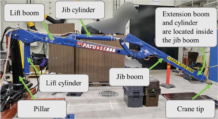
Figure 1 Mobile hydraulic log crane PATU 655, Laboratory of Intelligent Machines, LUT University, 2023 [22].
Mechanically, the crane can be described as a serial manipulator: a rotational pillar is mounted on a fixed base, with the lift and tilt (jib) booms interconnected sequentially via rotational joints. The extension boom is attached to the tilt boom with a linear joint. Each boom is actuated by its corresponding hydraulic cylinders.
3.1 Electro-hydraulic actuation system
In this study, the previously introduced electro-hydraulic actuation (EHA) system [12] was assembled in the Laboratory of Intelligent Machines at LUT University and integrated with the PATU 655 log crane. The hydraulic diagram of the experimental setup is presented in Figure 2 and the main components are listed in Table 1.
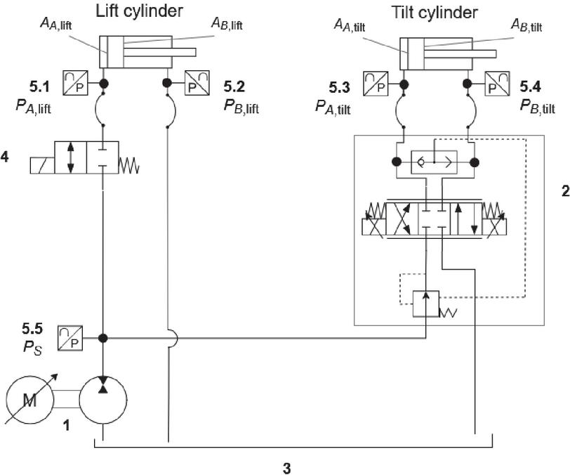
Figure 2 Hydraulic diagram of the experimental electro-hydraulic actuation system.
Table 1 Main components of the experimental electro-hydraulic actuation system integrated with the PATU 655 crane
| Component | Manufacturer and Code | Main Parameters |
| Lift cylinder | - | Piston diameter 100 mm |
| Rod diameter 56 mm | ||
| Stroke 535 mm | ||
| Tilt cylinder | - | Piston diameter 100 mm |
| Rod diameter 56 mm | ||
| Stroke 780 mm | ||
| Variable speed drive | Parker AC30 710-4G0060 [23] | Rated power 22 kW Output current 45 A |
| Electric motor | Parker GVM210-050 [24] | Rated power 22 kW DC voltage supply 540 V Rated speed 4000 rpm |
| Hydraulic pump | Parker F11-019 [25] | Displacement 19 cm3/rev |
| Controller | dSpace DS1202 MicroLabBox Platform | Analog input channel 28 Analog output channel 8 Digital input/output channel 3 |
| Pressure sensors | SICK PFT [26] | Pressure 0…250 bar |
| DCV | Danfoss PVG 32 PVB [27] | Max. continuous pressure 350 bar Max. flow 40 lpm |
The hydraulic power source of the system is the EHC 1, comprising a variable-speed electric motor and a fixed-displacement pump. It is directly connected to the lift cylinder piston-side chamber and also supplies the tilt cylinder through DCV 2. An on/off valve 4 is installed for load-holding and safety function and is engaged in the case of emergency shutoff.
3.2 System Modernization
The main limitation of the proposed system is that the supply line pressure must remain the highest in the circuit to guarantee sufficient pressure drop on the DCVs controlling the other cylinders. In [12], two principle strategies were proposed to address this limitation: first, increase the supply pressure and second, reduce the operating pressure of the remaining cylinders. The former can be realized by creating counterpressure in the rod-side chamber of the lift cylinder using an accumulator. The latter can be achieved by increasing the piston diameters of the remaining cylinders, thereby lowering their pressure demands.
The present study introduces active control of the lift cylinder rod-side chamber pressure. The supply line is connected to the rod-side chamber through a proportional DCV, enabling the control algorithm to automatically increase the supply line pressure by regulating the rod-side chamber pressure. In the laboratory setup, a Bosch Rexroth 4WRPEH 6 proportional DCV with a rated flow of 40 lpm was installed [28]. The modified hydraulic system is presented in Figure 3.
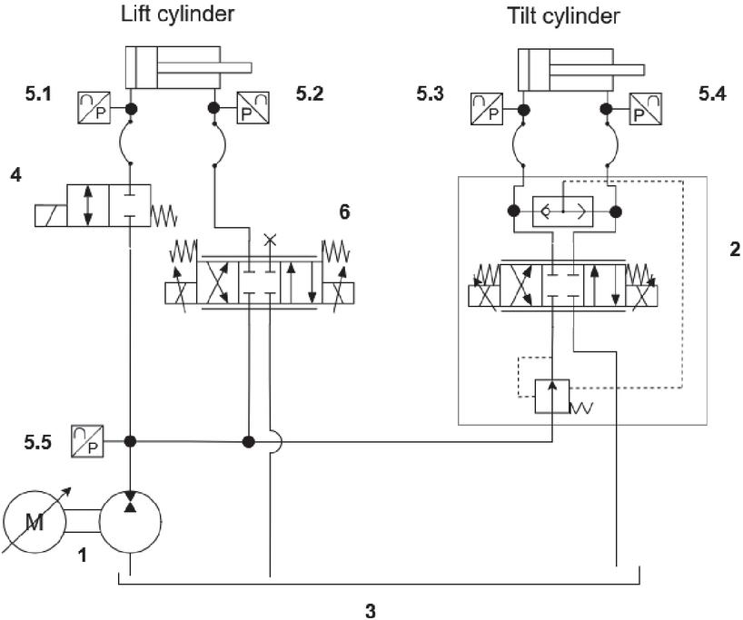
Figure 3 Hydraulic diagram of the modified electro-hydraulic actuation system with a proportional valve connected to the lift cylinder rod-side chamber.
Although the tilt cylinder pressure cannot exceed the supply line pressure in the considered crane configuration, a minimum pressure margin bar was required between the tilt cylinder pressure and the supply line . Accordingly, the reference pressure for the lift cylinder rod-side chamber was defined as:
where is the minimum set pressure in the lift cylinder rod-side chamber; is the highest measured pressure in the tilt cylinder, Pa; is the measured supply line pressure, Pa; and and are piston- and rod-side areas of the lift cylinder, m2.
The control of the lift cylinder rod-side chamber pressure is based on the valve flow equation:
| (1) |
where is the lift valve flow coefficient; is the flow to the lift cylinder rod-side chamber, estimated from the piston velocity and pressure feedback:
| (2) |
To further improve system control, the tank line of the tilt cylinder DCV was throttled using a variable orifice (7), as shown in Figure 4. This measure creates backpressure in the tilt cylinder DCV to prevent cavitation and reduce the runout of the cylinder during load lowering.
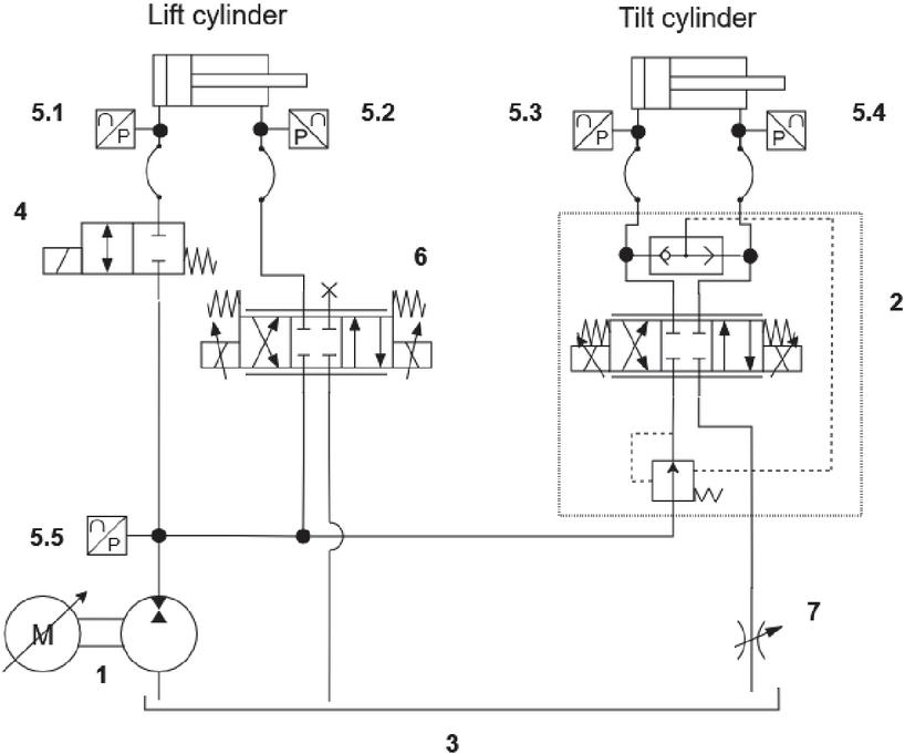
Figure 4 Hydraulic diagram of the modified electro-hydraulic actuation system with a proportional valve connected to the lift cylinder rod-side chamber and a throttled tank line of the tilt DCV.
3.3 Control Algorithm
The control algorithm was adapted to address practical implementation challenges. Its structure is shown in Figure 5.
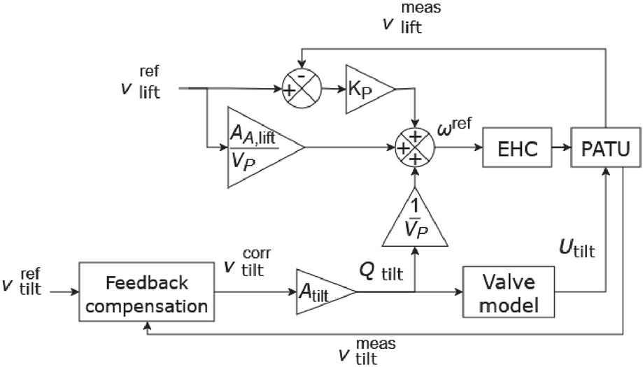
Figure 5 Diagram of the control algorithm.
The reference rotation velocity of the EHC, , is defined as:
| (3) |
where is the pump displacement, m3/rad; is the proportional feedback gain; is the volumetric flow to the tilt cylinder, m3/s; and is the pump leakage flow rate, m3/s. Figure 6 shows the pressure-dependent pump leakage coefficient (), obtained by combining low-pressure measurements with datasheet values at 200 bar and above.
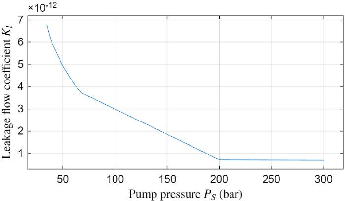
Figure 6 Pump leakage flow coefficient as a function of supply pressure.
The control signal for the tilt cylinder DCV, , is calculated using its parameters:
| (4) |
where is the set pressure drop of the valve pressure compensator, Pa; is the valve deadband voltage, V.
The required tilt cylinder flow is derived from the corrected tilt cylinder velocity :
| (5) |
The corrected velocity incorporates feedback compensation:
| (6) |
At near-zero velocities, two additional rules were introduced to improve the stability of low-speed motions:
4 Experimental Validation
The performance of the proposed system was evaluated in representative working cycles involving two typical crane operations: loading logs from a pile into a trailer and unloading them onto the ground. Due to the limited available workspace, only planar crane motion using the lift and tilt cylinders was considered. Since the crane was not equipped with a grapple, a payload of 180 kg was simulated by attaching metal plates to the crane tip, corresponding to the average mass of a single log. Figure 7 shows the experimental setup, including the hydraulic crane, a vertical obstacle representing the trailer bunks, and the defined start and end points of the cycle.
The crane was operated manually using two joysticks on a remote control unit, enabling the operator to perform the tasks from a safe distance while maintaining realistic visibility of the working area. The operator was instructed to move the crane tip between the target points around the obstacle in both directions. All tests were performed by the same operator and comprised 18 cycles, including both loading and unloading motions.
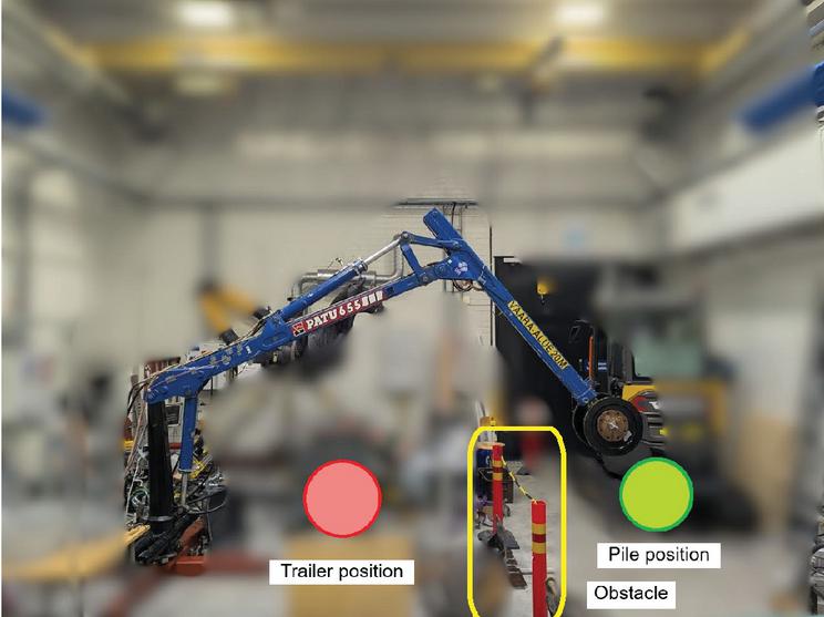
Figure 7 Hydraulic crane PATU 655 during experiments. The green circle marks the target pile position, the red one indicates the trailer, and the pillars with a chain represent the trailer bunks.
4.1 Reference System
The proposed electro-hydraulic actuation system is compared with a conventional LS system with pressure-compensated DCVs. Figure 8 presents the hydraulic diagram of the reference system. The same EHC 1 was used as the hydraulic power source, while cylinder control was performed through Danfoss PVG 32 PVB DCVs.
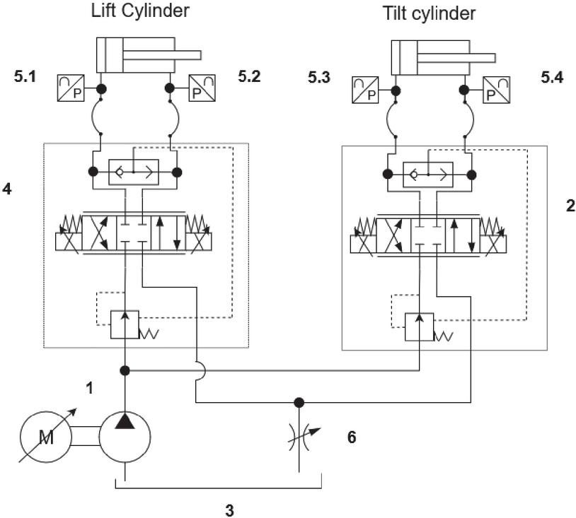
Figure 8 Hydraulic diagram of the reference LS system with pressure-compensated DCVs.
In an LS system, the supply pressure is maintained at a fixed margin above the highest actuators’ pressure, commonly 35 bar. This is traditionally achieved hydro-mechanically using a variable-displacement LS pump [29]. In the present setup, however, the supply pressure is regulated electronically by controlling the EHC’s rotation speed, based on real-time cylinder pressures measured with sensors 5.1-5.4.
The EHC reference rotation speed was calculated using proportional pressure feedback combined with flow demand compensation:
| (7) |
where is the highest measured cylinder pressure, Pa; is the pressure margin, Pa; is the proportional feedback gain; and are cylinder areas depending on the movement direction, m2.
5 Results
The total energy consumption of each experiment was obtained by integrating the measured power input of the variable-speed drive. This approach accounts for motor and inverter power losses. All measurements were recorded with a sampling rate of 1000 samples per second.
Let and be the total energy consumption and the cycle duration of the proposed system. Then and are those of the proposed system with pressurized lift cylinder rod-side chamber; and are those of the proposed system with a pressurized lift cylinder rod-side chamber and a throttled DCV tank line; and and – are those of the reference LS system.
Figure 9 presents box plots of energy consumption per cycle for all experiments. The corresponding summary statistics are provided in Table 2.
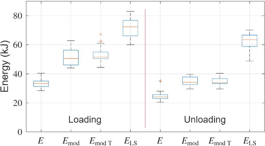
Figure 9 Energy consumption per cycle, where represents the proposed system; – the proposed system with a pressurized lift cylinder rod-side chamber; – the proposed system with a pressurized lift cylinder rod-side chamber and a throttled DCV tank line; – reference LS system.
Table 2 Summary statistics of energy consumption per cycle
| Parameters | , kJ | , kJ | , kJ | , kJ | |
| Loading logs | 75th percentile | 35.04 | 56.28 | 55.02 | 76.78 |
| Median | 33.41 | 50.54 | 51.50 | 72.37 | |
| 25th percentile | 31.29 | 46.10 | 50.41 | 66.17 | |
| Unloading logs | 75th percentile | 25.74 | 37.81 | 36.68 | 66.70 |
| Median | 24.11 | 34.18 | 33.93 | 63.53 | |
| 25th percentile | 23.02 | 32.65 | 33.23 | 58.90 | |
The cycle durations for each experiment are presented in Figure 10, with the corresponding statistics summarized in Table 3.
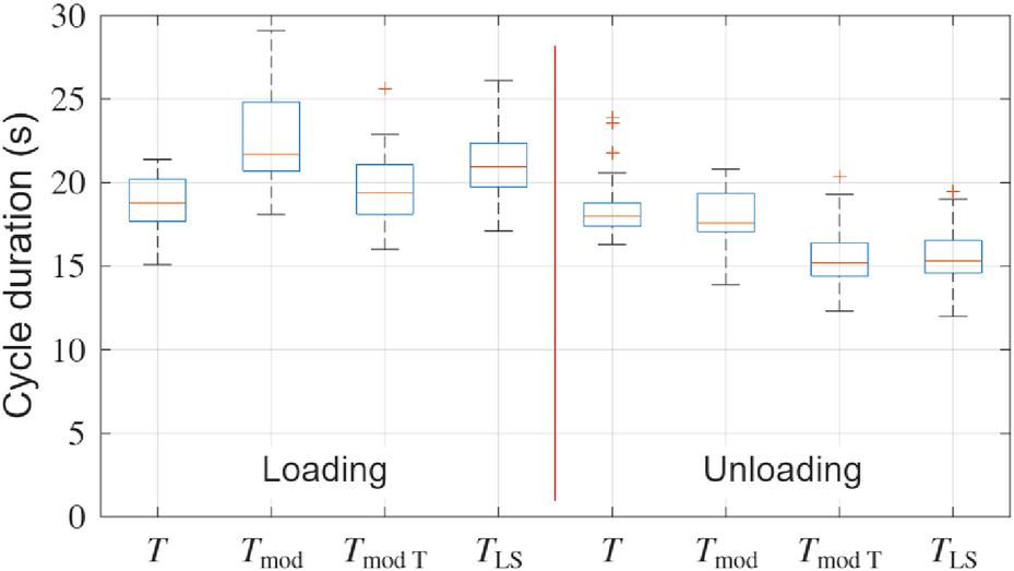
Figure 10 Cycle duration.
Table 3 Summary statistics of cycle duration
| Parameters | , s | , s | , s | , s | |
| Loading logs | 75th percentile | 20.20 | 24.83 | 21.08 | 22.37 |
| Median | 18.80 | 21.70 | 19.40 | 20.95 | |
| 25th percentile | 17.70 | 20.70 | 18.10 | 19.75 | |
| Unloading logs | 75th percentile | 18.80 | 19.35 | 16.40 | 16.55 |
| Median | 18.00 | 17.60 | 15.20 | 15.30 | |
| 25th percentile | 17.40 | 17.05 | 14.40 | 14.60 | |
The examples of the experiments are illustrated in Figures 11 and 12, which represent cylinder positions and pressures during loading and unloading cycles. As can be seen from the lift cylinder pressure plots, the rod-side pressure () is higher in both modified systems, suggesting that the supply pressure is actively increased to maintain the required pressure difference across the tilt DCV. Also, during the extension of the lift cylinder in the reference LS system, the rod-side pressure is elevated, illustrating the backpressure caused by valve flow resistance. This backpressure creates additional piston-side chamber pressure and can lead to a higher supply pressure, thereby increasing overall energy consumption.
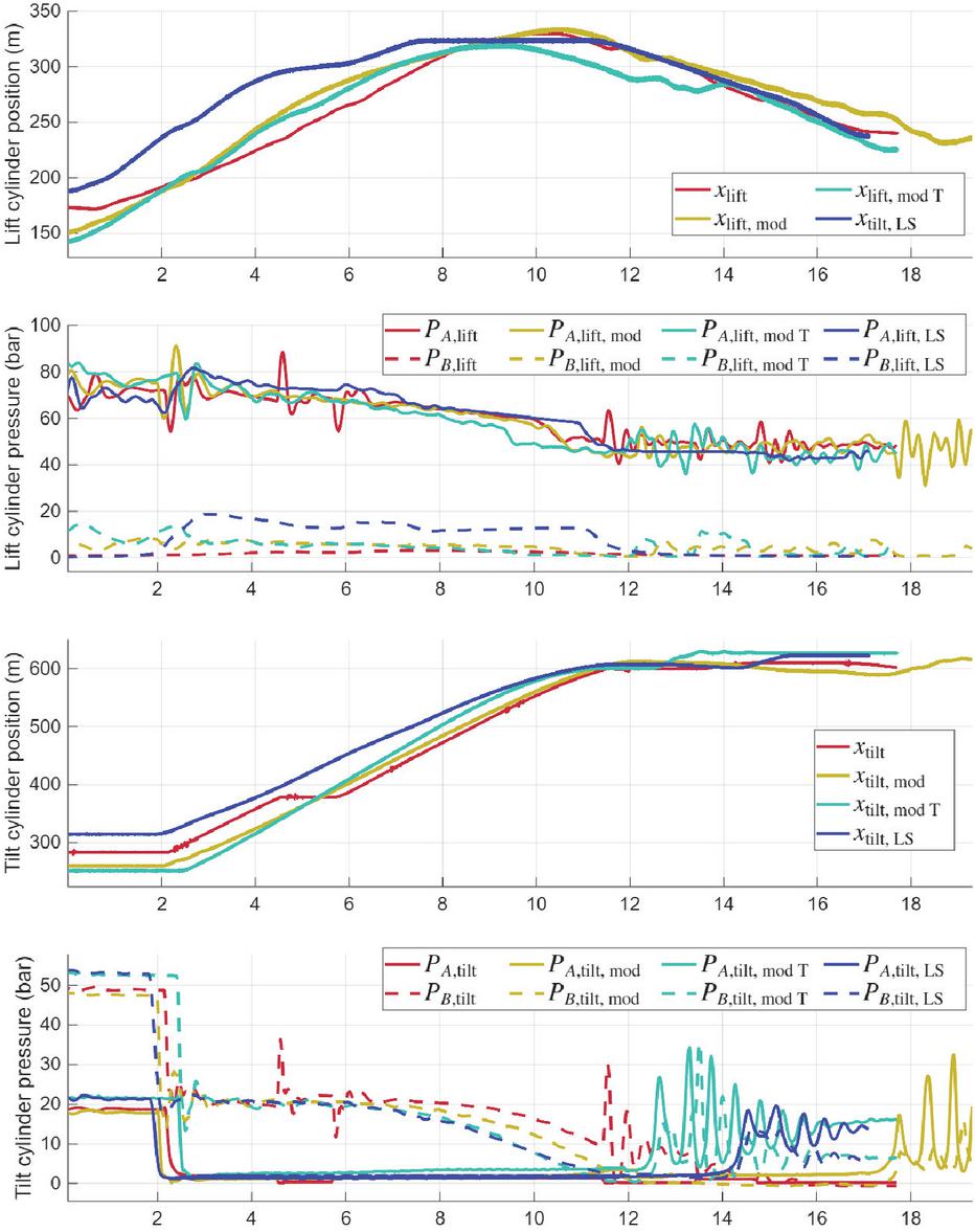
Figure 11 Example of cylinders positions and pressures during loading cycles.
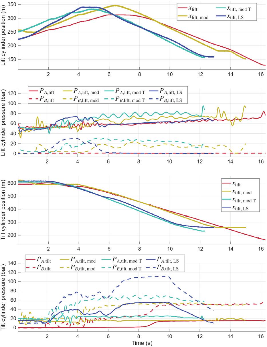
Figure 12 Example of cylinders positions and pressures during loading cycles.
6 Conclusions
This study presented the implementation and experimental validation of an electro-hydraulic actuation system for mobile cranes featuring valveless control of the lift cylinder. Applicability of the solution is limited by the requirement of a cylinder with a unidirectional loading, with its pressure maintained the highest in the system. Sufficient pressure margin can be secured with the proposed active pressurization of the lift cylinder rod-side chamber, but it leads to increased energy consumption.
Experiments confirmed statistically significant reduction in energy consumption during representative working cycles while maintaining identical productivity and payload, as illustrated in Figures 9 and 10 and quantified in Tables 2 and 3. The proposed system achieved median savings of 53.83% during log loading and 62.05% during log unloading cycles compared to the reference LS system with DCVs. Statistical testing confirmed that these differences were highly significant (two-sample Welch’s t-test, h 1, p 10-10).
To overcome the approach limitation and secure sufficient supply line pressure for the tilt cylinder, active pressurization of the lift cylinder rod-side chamber was introduced and experimentally validated. The modified system, with a pressurized lift cylinder rod-side chamber and a throttled DCV tank line, also demonstrated reduced energy consumption, with median saving of 28.84% during log loading and 46.59% during log unloading cycles compared to the reference system. These reductions were also statistically significant (two-sample Welch’s t-test, h = 1, p 10-18).
The effect of the proposed system on productivity and cycle duration remains inconclusive. As presented in Figure 10 and Table 3, statistically significant differences are observed only between the reference system and the proposed system (two-sample Welch’s t-test, h = 1, p 10-3), and between the reference system and the proposed system with a pressurized lift-cylinder rod-side chamber and a throttled DCV tank line (two-sample Welch’s t-test, h = 1, p 0.04). The variability in cycle duration is primarily attributed to manual control. Operator-dependent differences in motion control, timing, and control strategy distort systematic differences between architectures. As a result, the measured cycle durations largely reflect operator-induced variability rather than system performance, limiting the conclusions about productivity.
The energy savings are primarily attributed to several factors: first, direct actuation of the lift cylinder with an EHC enables energy recuperation during load lowering and significantly reduces throttling losses; and second, the lower supply line pressure decreases the pressure drop across the tilt cylinder DCV, further reducing throttling losses.
Deviations from previously reported results arise from differences in test formulation: in the simulations, the systems were evaluated using a predefined sequence of control commands, whereas the experiments were conducted following representative operator-controlled working cycles. In addition, the mathematical models used in the simulations did not include energy losses in the inverter, motor, gears, and pump.
The LS functionality in the reference system is implemented using a variable-speed, fixed-displacement EHC instead of a conventional constant-speed, variable-displacement pump. Although both approaches may demonstrate comparable efficiency under nominal conditions, differences in low-speed and idle losses highlight the need for a further systematic quantitative comparison with a conventional LS system.
The approach can be extended to a larger number of actuators, with additional cylinders controlled via DCVs. The EHC would be sized to meet the corresponding increase in flow demand. However, the overall energy efficiency strongly depends on the distribution of actuator workload. In applications where most operations are performed by actuators other than the lift cylinder, the achievable energy savings are reduced and result primarily from lower supply pressure and the associated reduction in throttling losses. Consequently, the energy-saving potential of the proposed solution is application-dependent, and a systematic application-specific evaluation remains for future work.
CRediT Authorship Contribution Statement
Timofei Komarov: Writing – original draft, Conceptualization, Methodology, Software, Validation, Formal analysis, Investigation, Data Curation, Visualization, Project administration. Victor Zhidchenko: Writing – review & editing, Conceptualization, Methodology, Software, Validation, Formal analysis, Investigation, Supervision. Heikki Handroos: Writing – review & editing, Supervision, Resources, Methodology, Funding acquisition.
Declaration of Competing Interest
The authors declare that they have no known competing financial interests or personal relationships that could have appeared to influence the work reported in this paper.
Funding
This work was supported by LUT Doctoral School, Finland.
References
[1] J. Kalmari, J. Backman, and A. Visala, “Coordinated motion of a hydraulic forestry crane and a vehicle using nonlinear model predictive control,” Computers and Electronics in Agriculture, vol. 133, pp. 119–127, 2017.
[2] J. Koivumäki and J. Mattila, “High performance nonlinear motion/force controller design for redundant hydraulic construction crane automation,” Automation in Construction, vol. 51, pp. 59–77, 2015.
[3] Ponsse, “The perfect cut. ctl – the cut-to-length method,” Ponssentie 22, 74200 Vieremä, 2023.
[4] A. Mahmood, S. F. Abedin, M. O’Nils, M. Bergman, and M. Gidlund, “Remote-timber: An outlook for teleoperated forestry with first 5g measurements,” IEEE Industrial Electronics Magazine, vol. 17, no. 3, pp. 42–53, 2023.
[5] V. Waurich, B. Beck, J. Weber, and F. Will, “Levels of digitalization for construction machinery on the connected and automated construction site,” in Construction logistics, equipment, and robotics, (Cham), pp. 157–165, Springer Nature Switzerland, 2024.
[6] G. P. Moreda, M. Muñoz Garcia, and P. Barreiro Elorza, “High voltage electrification of tractor and agricultural machinery – a review,” Energy Conversion and Management, vol. 115, pp. 117–131, 2016.
[7] T. Lin, Q. Wang, B. Hu, and W. Gong, “Development of hybrid powered hydraulic construction machinery,” Automation in Construction, vol. 19, no. 1, pp. 11–19, 2010.
[8] S. Qiao, Y. Hao, L. Quan, L. Ge, and L. Xia, “A novel electro-hydraulic compound driving system with potential energy regeneration capability for lifting device,” IEEE Access, vol. 10, pp. 18248–18256, 2022.
[9] S. Du, J. Zhou, J. Hong, H. Zhao, and S. Ma, “Application and progress of high-efficiency electro-hydrostatic actuator technology with energy recovery: A comprehensive review,” Energy Conversion and Management, vol. 321, pp. 1–24, 2024.
[10] D. Fassbender, C. Brach, and T. Minav, “Energy-efficiency comparison of different implement powertrain concepts to each other and between different heavy-duty mobile machines,” International Journal of Fluid Power, vol. 25, p. 127–144, Jul. 2024.
[11] S. Ketelsen, D. Padovani, T. O. Andersen, M. K. Ebbesen, and L. Schmidt, “Classification and review of pump-controlled differential cylinder drives,” Energies, vol. 12, no. 7, pp. 1–27, 2019.
[12] T. Komarov, D. Zadorozhniuk, H. Handroos, and J. Pyrhönen, “Valve-free operation of the lift cylinder in mobile machines with an electrohydraulic actuation system,” in 2024 IEEE 20th International Conference on Automation Science and Engineering (CASE), pp. 1100–1105, IEEE, 2024.
[13] C. Williamson, J. Zimmerman, and M. Ivantysynova, “Efficiency study of an excavator hydraulic system based on displacement-controlled actuators,” in Bath ASME Symposium on Fluid Power and Motion Control (FPMC2008), pp. 291–307, 2008.
[14] L. Ge, L. Quan, Y. Li, X. Zhang, and J. Yang, “A novel hydraulic excavator boom driving system with high efficiency and potential energy regeneration capability,” Energy Conversion and Management, vol. 166, pp. 308–317, 2018.
[15] L. Schmidt, M. v. Binsbergen-Galán, R. Knöll, M. Riedmann, B. Schneider, and E. Heemskerk, “Energy efficient excavator implement by electro-hydraulic/mechanical drive network,” International Journal of Fluid Power, vol. 25, no. 04, p. 413–438, 2024.
[16] F. Zappaterra, D. Pan, T. Ransegnola, A. Vacca, S. D. Sudhoff, and E. Busquets, “A novel electro-hydraulic unit design based on a shaftless integration of an internal gear machine and a permanent magnet electric machine,” Energy Conversion and Management, vol. 310, pp. 1–23, 2024.
[17] S. Qu, F. Zappaterra, A. Vacca, and E. Busquets, “An electrified boom actuation system with energy regeneration capability driven by a novel electro-hydraulic unit,” Energy Conversion and Management, vol. 293, pp. 1–17, 2023.
[18] E. Busquets and M. Ivantysynova, “Priority-based supervisory controller for a displacement-controlled excavator with pump switching,” in Proceedings of the ASME/BATH 2015 Symposium on Fluid Power and Motion Control, no. V001T01A014 in Fluid Power Systems Technology, 2015.
[19] T. Bekele, R. Åman, and H. Handroos, “The control of multiple actuators using single iehec pump/motor,” in 10th International Fluid Power Conference (10. IFK), pp. 73–88, Nature Publishing Group, 2016.
[20] T. Komarov, V. Zhidchenko, and H. Handroos, “Automatic sequential actuation of multiple cylinders in mobile cranes using a single electro-hydraulic converter,” in The 19th Scandinavian International Conference on Fluid Power, SICFP’25, pp. 1–8, River Publishers, 2025.
[21] S. Qu, Z. Liu, R. Cardoso, and E. Busquets, “A compensator-less load sensing system designed for electrified compact track loader,” International Journal of Fluid Power, vol. 26, p. 187–210, July 2025.
[22] V. Zhidchenko, T. Komarov, A. Williot, N. Bauer, and H. Handroos, “A method for planning the trajectory of mobile hydraulic crane booms with a focus on energy efficiency,” in 2023 IEEE 21st International Conference on Industrial Informatics (INDIN), pp. 1–7, IEEE, 2023.
[23] Parker Hannifin Corporation, Variable Speed Drive – AC30 Series. Parker Hannifin Corporation, 2023.
[24] Parker Hannifin, Hydraulic Pump and Power Systems, GVM Global Vehicle Motor Power Series. Permanent Magnet (PMAC) Motor for Mobile Systems. Parker Hannifin, 2022.
[25] Parker Hannifin, Mobile Controls Division, Catalogue HY17-8249/US – Hydraulic Motor/Pump Series F11/F12. Parker Hannifin, 2004.
[26] S. AG, Product overview PFT. Precise pressure transmitter with flush-mounted process connections for flexible use. SICK AG, 2025.
[27] Danfoss, Proportional Valve Group. Danfoss, 2019.
[28] Bosch Rexroth AG, RE 29121. Bosch Rexroth AG, 2022.
[29] H. Pedersen, T. Andersen, and M. Hansen, “Load sensing systems – a review of the research contributions throughout the last decades,” in Proceedings 4th IFK Workshop, pp. 125–139, 2004.
Biographies

Timofei Komarov received his Master of Science degree in Mechanical Engineering from LUT University in 2022. His research focuses on the automation and electrification of mobile cranes.

Victor Zhidchenko received his D.Sc. (Tech.) degree from LUT University in 2019. With a broad background in computer science and high-performance computing, he has recently applied his expertise to the mechanical engineering, focusing on model-based digital twins and cyber-physical systems.

Heikki Handroos received his D.Sc. (Tech.) degree from Tampere University of Technology in 1991. Since 1993, he has led the Laboratory of Intelligent Machines at LUT University and was promoted to Full Professor in 1998. His research interests range from modeling, simulation, and control of mechatronic systems to robotics, hybrid transmission, and mobile machinery.
International Journal of Fluid Power, Vol. 27_3, 539–562
doi: 10.13052/ijfp1439-9776.2733
© 2026 River Publishers