Dimensioning Downstream-Throttled Pneumatic Cylinders with Time-Controlled Quick-Exhaust Valves
Luca Päßler*, Olivier Reinertz and Katharina Schmitz
Institute for Fluid Power Drives and Systems (ifas), RWTH Aachen University, Campus-Boulevard 30, D-52074 Aachen, Germany
E-mail: luca.paessler@ifas.rwth-aachen.de
*Corresponding Author
Received 22 March 2026; Accepted 22 September 2026
Abstract
Time-controlled pneumatic-mechanical quick-exhaust valves have been demonstrated to significantly improve the energy efficiency of downstream-throttled pneumatic cylinders for motion tasks [1]. This enhancement is achieved by decreasing the cylinder movement time, allowing for smaller cylinder sizing and thereby exploiting the strong relationship between air consumption and movement time. Previous experimental results of selected drives and load configurations indicate that downsizing by a minimum of one standard cylinder size is feasible with this approach. This reduction in size is essential to increase efficiency.
Therefore, this paper introduces a novel dimensioning method for pneumatic cylinders equipped with a time-controlled quick-exhaust valve. The proposed method is based on an algebraic sizing formula derived from a mathematical model describing the cylinder velocity. The experimental validation of this model demonstrates its capacity to accurately predict transfer times and to provide deeper understanding of the technology’s potential.
Keywords: Pneumatics, pneumatic cylinder, energy saving circuit, sizing method, end cushion, energy efficiency.
1 Introduction and State of the Art
The energy efficiency of pneumatic cylinders is closely linked to their correct dimensioning for the specific motion task [2, 3]. At present, downstream throttling is the primary method used to control the velocity and cycle time of pneumatic cylinders [4]. This method, however, is considered energy-inefficient, since the maximum amount of compressed air is consumed. Additionally, the energy efficiency is often diminished in practice by oversizing cylinders to compensate for uncertainties as to whether an ideally sized drive will reliably perform the task, leading to excessively large safety margins [5]. To address this challenge, various dimensioning approaches have been developed.
Dimensioning methods for pneumatic drives can generally be divided into two categories. The first category addresses force-based applications, in which the cylinder is selected primarily according to the required process force, for example in lifting, pressing, or clamping operations. The second category comprises movement-time-oriented methods for inertial motion tasks, where the required cylinder force is dominated by inertia and the objective is to achieve a prescribed movement while minimizing energy consumption. The present work belongs to the latter category and therefore focuses on inertial motion tasks without significant external process forces.
Doll et al. [6] introduced a heuristic approach for the dimensioning of pneumatic cylinders with a focus on energy efficiency, which has gained widespread acceptance in academic and industrial settings [2, 3, 7]. Their approach is based on the lowest occurring eigenfrequency of the cylinder during motion and considers similarity transformations. The ratio of the eigenfrequency to the required actuator dynamics is termed the pneumatic frequency ratio (PFR), denoted , and is defined as
| (1) |
where represents the movement time, is the cylinder stiffness at mid-stroke, and denotes the moving mass. An actuator is considered well-dimensioned when the PFR is between (1) and (7) [6]. The cylinder stiffness can be approximated by [8]
| (2) |
where denotes the piston area, the supply pressure, and the cylinder length. This approximation assumes that both chambers are pressurized with supply pressure. By combining Equations (1) and (2), the final dimensioning equation can be derived:
| (3) |
By incorporating the air consumption, Doll et al. [6] derived a relationship between the compressed air demand per stroke and the movement time:
| (4) |
where is the ambient pressure.
Reese et al. [5] proposed a novel approach for dimensioning downstream-throttled cylinders based on the capacity of the pneumatic end-cushion. The end-cushion is used in pneumatic cylinders to decelerate the movement of the piston at the end of the stroke and thus minimize the impact energy. In their method, Reese et al. approximate the piston motion based on two assumptions:
1. A constant velocity during the stroke;
2. Within the end-cushion, the velocity follows the transient step response of an underdamped second-order system.
Using these assumptions and the boundary condition that the velocity and acceleration at the end of the stroke must be zero, they derived a relationship between the entry velocity of the piston entering the end-cushion and the eigenfrequency of the cylinder within the end-cushion:
| (5) |
The eigenfrequency of the cylinder within the end-cushion is approximated by
| (6) |
where and denote the relevant geometric parameters of the end-cushion and is the pressure in the end-cushion at the moment of entry. By combining Equations (5) and (6) and assuming a constant piston velocity during the stroke, the following relationship can be derived:
| (7) |
Finally, this equation can be transformed into an algebraic dimensioning formula:
| (8) |
As Equation (8) shows, the dimensioning method proposed by Reese et al. [5] does not require the PFR, which results in significantly more accurate results compared to the dimensioning method by Doll et al. [6].
Equation (8) reveals a quadratic-reciprocal relationship between the end-cushion volume and the movement time. Since the total cylinder volume scales with the end-cushion size, technologies that increase the achievable dynamics of a pneumatic cylinder allow the required movement time to be met with a smaller cylinder size. Consequently, they can lead to disproportionately large reductions in compressed-air consumption.
Building on this knowledge, Reinertz et al. [9] have developed an energy-saving circuit (ESC) aimed at increasing the energy efficiency of pneumatic cylinders. Their concept relies solely on controlling the exhaust air to enhance the performance of downstream-throttled cylinders by using a switchable quick-exhaust (SQE) valve, which is installed in parallel to the downstream throttle [9]. The SQE valve is a pneumatic-mechanical quick-exhaust valve that allows for enhanced acceleration at the onset of the stroke. After a preset time, the valve closes, so that the cylinder transitions to a conventional downstream-throttled setup, thereby decelerating the piston to avoid overloading the end-cushion. The cylinder movement can be divided into these distinct phases:
1. Acceleration with quick-exhaust active;
2. Deceleration by downstream-throttling;
3. Gentle stopping in the end-cushion.
By dividing the motion into these phases, the energy usage is more efficient compared to the conventional downstream-throttled drive [10]. The functionality of the SQE valve concept was investigated in a lumped parameter simulation [11] and has been experimentally verified [1]. The results show that the performance of the cylinder can be significantly improved by using the SQE valve. This improvement grows with increasing cylinder length. While short cylinders with a length of 0.2 m achieve normalized air savings of 0 to 30%, long cylinders of 0.5 m length achieve normalized air savings of up to 70%. The results of the SQE valve are very promising. However, the exact influence of the SQE valves on motion dynamics and movement time remains unclear.
A concept for an energy-saving circuit very similar to SQE valves was patented by SMC Corporation in 2021 [12]. The concept is also based on dividing the movement using pneumatic time control. In contrast to SQE valves, however, no additional flow cross-section is opened at the start of the movement. Instead, an additional throttle is activated at the end of the movement to increase the downstream resistance and thus reduce the velocity [12]. In 2023, the concept was further developed by SMC Corporation and patented again [13], and has since been available on the market as a commercial product, called SMC Deceleration Controller [14].
The concept of enhancing the energy efficiency of pneumatic drives through the implementation of appropriate ESCs has been the subject of extensive research in numerous circuit configurations [2, 15–17]. While some isolated models that mathematically describe the dynamic behavior of some of these circuits exist, these models are predominantly formulated as differential equations [18–20]. Although these models can serve as a basis for simulations or optimization tasks, they do not provide explicit closed-form equations for the velocity as a function of operating conditions, for example. This lack of mathematical description also leads to an over-estimation of energy savings, since the correlation between air consumption and movement time is not considered. Reducing air consumption at the expense of movement time can in some cases even lead to poorer energy efficiency when the normalized air consumption is considered [21]. This complicates the practical application of ESCs, as the dimensioning of cylinders with an ESC can only be estimated roughly. Moreover, the absence of a mathematical description poses challenges in conducting detailed comparisons among various technologies, thereby impeding the selection of the most suitable ESC for specific applications.
This paper presents an analytical dimensioning method for inertial pneumatic motion tasks using SQE valves. Based on a simplified movement model, an algebraic equation for predicting the movement time is derived. In addition, a minimum conductance criterion is proposed to define the applicability range of the analytical model and to verify that the cylinder dynamics are governed by pneumatic stiffness rather than by flow limitations. Finally, a simplified engineering design rule based on the established eigenfrequency method is derived to facilitate practical industrial dimensioning.
2 Simplified Movement Model of a Cylinder with Time-Controlled Quick-Exhaust Valves
In order to derive a dimensioning method, a simplified movement model of the cylinder dynamics is required, which takes into account the relationships between the most important parameters and boundary conditions. Therefore, in this section, a simplified movement model of a cylinder with SQE valves is developed, building on the dimensioning method for downstream-throttled drives by Reese et al. [5]. First, the functionality and implementation of the novel circuit are elucidated, then the validity of the two assumptions posited by Reese et al. [5] for the novel circuit is examined. Finally, the new simplified movement model is presented.
2.1 Implementation of the Switchable Quick-Exhaust Valves
The fundamental design of the novel circuit incorporating SQE valves is described below, with the precise technical implementation delineated in Päßler et al. [1]. Figure 1(a) illustrates a state-of-the-art pneumatic drive in a downstream-throttled configuration, in which a throttle-check valve (item 1) generates a back-pressure within the passive chamber of the cylinder, thereby counteracting the movement and enabling the adjustment of the cylinder’s velocity. The direction of movement is reversed by the 5/2-way valve (item 2).
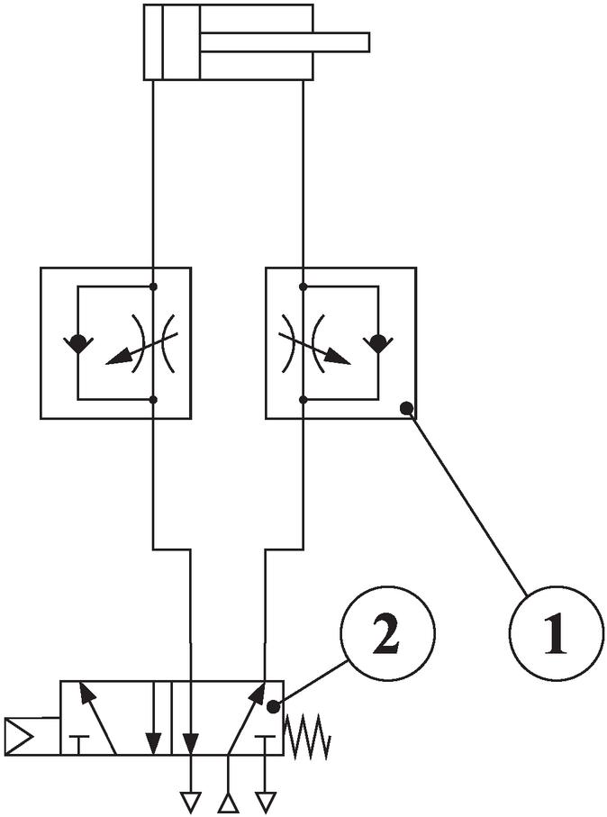
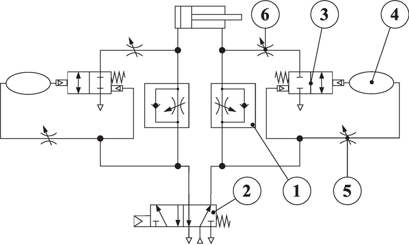
Figure 1 Schematic representation of (a) a downstream-throttled drive and (b) a downstream-throttled drive with switchable quick-exhaust valves.
In the novel circuit, a pneumatically controlled 2/2-way valve (item 3) is arranged in parallel to the downstream throttle, as shown in Figure 1(b). When this valve opens, an additional flow cross-section to the environment results, which dramatically reduces downstream resistance. The valve opens after a sudden pressure drop within the pneumatic line extending from the controlling 5/2-way valve to the downstream throttle. This pressure drop occurs on the newly passive side when the movement direction changes. The valve is held open by the pressure within a dead volume (item 4), which declines, since the air in this dead volume is exhausted through an adjustable throttle (item 5). As soon as the pressure falls below a certain level, the valve is closed by a mechanical spring; the circuit then reverts to a downstream-throttled configuration. By adjusting the conductance of the throttle (item 5), the period for which the quick-exhaust remains active is set. The magnitude of the quick-exhaust while the valve is open can be tuned with the throttle between the cylinder and the 2/2-way valve (item 6).
2.2 Cylinder Dynamics in the End-Cushion
The adjustment of the end-cushion damping determines the impact energy of the cylinder at the end of the stroke, which should be as low as possible to reduce noise and wear [22, 23]. Reese et al. [5] demonstrated the importance of the end-cushion damping for the correct dimensioning of downstream-throttled pneumatic cylinders. According to their dimensioning method, the velocity in the end-cushion can be modeled as the step response of an under-damped second-order system. The underlying speed step is attributed to a change in downstream resistance when entering the end-cushion. The boundary conditions in Table 1 were employed in the derivation of the simplified movement model, whereby represents the cylinder length, the length of the end-cushion, the piston position, and the optimal entry velocity into the end cushion.
Table 1 Boundary conditions for the velocity curve in the pneumatic end-cushion
| 0 | ||
| 0 | 0 |
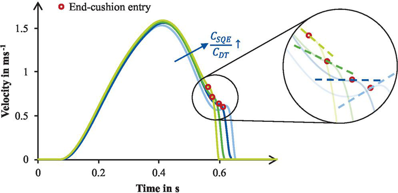
Figure 2 Influence of the downstream throttle conductance to quick-exhaust conductance ratio on the dynamics at the end-cushion entry.
As the downstream-throttled system, the new system equipped with SQE valves should reach zero velocity and acceleration at the end stop. In the previous system, the sole variable that could be modified was the entry velocity. This modification was achieved by adjusting the conductance of the downstream throttle, . Consequently, conventional downstream-throttled systems possess precisely one setting that results in an optimal motion profile. In the new system, however, the conductance of the quick-exhaust valve throttle (item 6 in Figure 1(b)) can also be modified. Figure 2 presents the various velocity curves that were recorded at varying ratios of to . The curves are simulation results of a cylinder with a length of 0.5 m, a piston diameter of 25 mm, and a moving mass of 10 kg. The simulation model is described in Reinertz et al. [11]. Despite the considerable variation in velocity and acceleration at the entry of the end-cushion, the curves culminate in a velocity and acceleration of zero at the end stop. The augmented degree of freedom inherent in signifies that the novel system possesses not merely a single optimal operating point, but rather one optimal operating point for each possible value of . Because the SQE valve introduces an additional degree of freedom compared to a conventional downstream-throttled cylinder, an additional criterion is required to define the ideal movement behavior. In this work, robustness against disturbances at the end-cushion entry is selected as this criterion.
In the dimensioning method for downstream-throttled cylinders based on the end-cushion, the acceleration at the beginning of the end-cushion is assumed to be zero, which is clearly visible to be not the case for a system with SQE valves. A more thorough investigation of the dynamics at end-cushion entry requires an additional parameter in the velocity equation. This parameter is introduced as a phase shift, denoted . The phase shift parameterizes the nominal velocity profile in the end-cushion and is directly related to the entry acceleration. A phase shift of corresponds to zero entry acceleration, whereas positive and negative entry accelerations correspond to negative and positive values of , respectively. This parameter allows the velocity in the end-cushion to be expressed as a function of the entry velocity under the assumption of second-order behavior, as shown in Equation (9).
| (9) |
The variable denotes the natural frequency of the cylinder in the end-cushion. For any value of , Equation (10) can be used to determine the magnitude of the target velocity step that satisfies the prescribed boundary conditions, i.e., the piston comes to rest exactly at the end stop with zero velocity and zero acceleration.
| (10) |
Equation (10) is obtained by integrating Equation (9) over the available end-cushion length and solving for under the boundary conditions listed in Table 1. Thus, represents the unique velocity-step amplitude that results in ideal end-cushioning.
Figure 3 shows the optimal velocity curves in the end-cushion, calculated from Equations (9) and (10) for different values of . The curves indicate that the required entry velocity decreases as the entry acceleration increases in order to achieve optimal stand-still at the end stop.
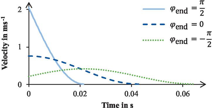
Figure 3 Optimally adjusted movement behavior in the end-cushion under different entry conditions, determined by the phase shift .
To reduce the number of free model parameters, only one specific phase shift is further analyzed in the following.
One obvious choice for this phase shift could be the one that minimizes movement time. As illustrated in Figure 2, the movement time decreases with reduced acceleration, but the effect is small. Robustness therefore becomes the more relevant criterion. Deviations from the optimal entry conditions, for example, due to changing operating pressures, can cause the cylinder to hit the end stop with an impact velocity instead of stopping smoothly. A robust system exhibits only a small increase in impact velocity when such deviations occur.
After selecting a nominal phase shift , the robustness of the resulting movement behavior against deviations from the nominal operating point is investigated. Two types of disturbances are considered: a relative deviation in the entry velocity and an absolute deviation in the entry acceleration . The acceleration deviation is defined as the deviation from the entry acceleration associated with the selected nominal phase shift. For the evaluation, this disturbed entry acceleration is converted into the corresponding phase shift , yielding Equations (11) and (12). Consequently, is not an additional model parameter but a disturbance of the nominal entry acceleration represented by the selected phase shift. Integrating these equations and equating the result to the end-cushion length yields the impact velocity. Although a closed-form solution is not available, the equations can be solved iteratively with little computational effort, making it straightforward to examine how affects robustness.
| (11) | ||
| (12) |
Figure 4(a) plots the impact velocity for various deviations in entry velocity and different phase shifts. Figure 4(b) presents the corresponding results for deviations in entry acceleration.
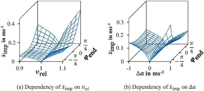
Figure 4 Impact velocity at the end stop dependent on the phase shift , the relative deviation from the optimal velocity and the deviation from the optimal acceleration at the end-cushion entry.
As illustrated in Figure 4(a), phase shifts around zero produce the lowest impact velocities when the entry velocity varies. Negative phase shifts affect only slightly the impact velocity. Positive phase shifts, on the other hand, strongly increase the impact velocity at varying entry velocity. When the entry acceleration varies, phase shifts near zero again enhance robustness, as shown in Figure 4(b), whereas negative phase shifts are detrimental. To ensure robust performance, it is therefore advisable to select a velocity curve with zero phase shift, which corresponds to zero acceleration at end-cushion entry. This choice is consistent with the first assumption used in the end-cushion-based dimensioning of downstream-throttled cylinders (Table 1). With this assumption, the formulas simplify, and the optimal entry velocity can be calculated with Equation (13).
As illustrated in Figure 4(a), phase shifts around zero produce the lowest impact velocities when the entry velocity varies. Negative phase shifts affect the impact velocity only slightly, whereas positive phase shifts strongly increase the impact velocity under varying entry velocities. When the entry acceleration varies, phase shifts close to zero again provide the highest robustness, as shown in Figure 4(b), while negative phase shifts are detrimental. To ensure robust performance, it is therefore advisable to select a velocity curve with zero phase shift, corresponding to zero acceleration at the end-cushion entry. This choice is consistent with the assumption used by Reese et al. [5] for the dimensioning of downstream-throttled cylinders.
For , Equations (9) and (10) reduce to the corresponding special case presented by Reese et al. [5]. Evaluating the resulting velocity equation at the beginning of the end-cushion yields the required entry velocity for ideal end-cushioning. By substituting the natural frequency from Equation (6), the following expression is obtained:
| (13) |
2.3 Cylinder Dynamics During the Stroke
The second assumption of the dimensioning method for downstream-throttled cylinders concerns the cylinder velocity during the stroke, i.e., before entry into the end-cushion. In that method, this velocity is assumed to be constant. Figure 5 shows the measured velocity of a cylinder with a 25 mm diameter, 0.5 m stroke, 10 kg moving mass and a supply pressure of 7 bar, equipped with SQE valves (blue). For comparison, the constant optimal entry velocity into the end-cushion is plotted (green dashed line). The figure indicates that the constant-velocity assumption overestimates the initial velocity and later underestimates it. The same effect occurs in the dimensioning of the conventional downstream-throttled system, but there the two errors largely cancel each other. In the novel system, however, the two shaded areas in the figure do not balance, so the second assumption is no longer valid. Consequently, a new model is required to predict the dynamics and thus the movement time of the SQE-equipped cylinder.
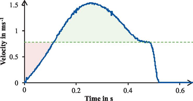
Figure 5 Comparison of the cylinder velocity with SQE valves with a constant velocity.
2.4 Simplified Movement Model
In the new model, the stroke before the end-cushion is no longer treated as a single phase but is divided into two sections. This subdivision reflects the switching of the SQE valve, which changes the system from quick-exhaust to downstream throttling. The resulting steps in downstream resistance define the phase boundaries.
• Phase 1 (acceleration phase) begins with an immediate drop in downstream resistance when the active and passive chambers are exchanged. The piston therefore accelerates rapidly.
• In phase 2 (deceleration phase) the circuit switches to downstream throttling, causing a sharp rise in downstream resistance that decelerates the piston. A further rise occurs with the end-cushion entry.
Table 2 Boundary and transfer conditions for the cylinder velocity in the novel system
| Movement | Switch of | End-cushion | Movement | |
| Start | SQE Valve | Entry | End | |
| Time | 0 | |||
| Position | 0 | |||
| Velocity | 0 | 0 | ||
| Acceleration | 0 | 0 | 0 | 0 |
Each step in exhaust resistance produces a corresponding step in the cylinder’s target velocity. The resulting velocity changes are modeled as the step response of a second order element, a topic which has been extensively investigated [24]. The boundary and transition conditions used for the derivation of the new dimensioning method are listed in Table 2. As argued in Section 2.2, maximum robustness requires zero acceleration at every transition, therefore the acceleration is set to zero both at the change from acceleration to deceleration phase and at entry into the end-cushion.
The total time needed for the piston to traverse the stroke is the movement time . The SQE valve switching time is , and the time of entry into the end-cushion is . The velocity steps , the natural frequencies , and the damping coefficients differ in each section. Together with the boundary and transfer conditions, they yield a simplified movement model, illustrated in Figure 6.
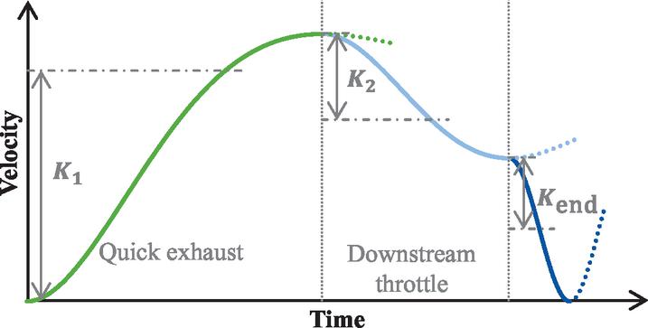
Figure 6 Simplified movement model of the cylinder dynamic.
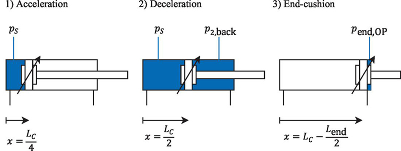
Figure 7 Operating points for the calculation of the natural frequencies in each section.
The assumed operating points are summarized in Figure 7. Representative operating points are selected for each movement section to estimate the corresponding natural frequency. They are not intended to represent the transition locations between the movement phases but rather average positions at which the chamber stiffness, and consequently the natural frequency, is assumed to be representative of the respective phase. When the natural frequencies are calculated with Equation (14), the difference between extension and retraction strokes must be considered because the piston areas differ. By incorporating the virtual length , the dead volume of the pneumatic lines and components can be considered [6]. A polytropic exponent of is assumed.
• Section 1: The operating point is selected at , representing the midpoint of the acceleration phase. Since the acceleration phase covers approximately the first half of the stroke before the transition to the deceleration phase, provides a representative operating point for estimating the natural frequency. Owing to the active quick exhaust, the back pressure in the passive chamber is negligible, and the supply pressure is therefore the only relevant pressure.
• Section 2: The operating point is selected at , representing the midpoint of the deceleration phase. At this point, the circuit has already switched to downstream throttling, so the back pressure is no longer negligible. Since the acceleration is assumed to be zero at the transition between the acceleration and deceleration phases, the back pressure is determined from the corresponding force equilibrium.
• End-cushion: The operating point is selected at half the end-cushion length. The natural frequency is determined analogously to Reese et al. [5] using the operating pressure .
| (14) |
The damping coefficients are obtained from the ratio of the viscous-friction coefficient to twice the moving mass times the natural frequency, as described by Reese et al. [5]. Because this ratio is typically very small, the damping coefficient is set to zero, resulting in an undamped system.
| (15) |
This assumption leads to Equation (16), which describes the velocity in each phase. Incorporating the conditions from Table 2 yields a system of equations which enables to derive the magnitudes of the velocity steps at the start of each phase, Equation (17).
| (16) | ||
| (17) |
An expression is still required for the pressures and . Because the acceleration at the beginning of each section is zero, a force equilibrium exists at the piston. From this equilibrium the following expression is obtained:
| (18) |
where is the ratio of rod-side to piston surface area [5].
For simplicity, Equation (18) neglects external forces and friction, so that the force equilibrium is governed solely by the chamber pressures. This assumption is consistent with the experimental validation presented in Section 4, where the cylinders operate horizontally without external process forces. Furthermore, the pressure in the driving chamber is approximated by the supply pressure. Although pressure losses occur during the movement owing to valve restrictions and the increasing chamber volume, these effects are neglected to obtain a simple algebraic dimensioning method. Consequently, the operating pressures should be regarded as representative average values rather than exact chamber pressures. The experimental validation demonstrates that these assumptions provide sufficient accuracy for predicting the movement time.
3 Dimensioning Method
The simplified movement model derived in the previous section can be used to calculate the movement time as a function of the operating conditions and the cylinder geometry. Because the piston velocity completes roughly half of a sinusoidal oscillation in each phase, the stroke time is governed primarily by the natural frequencies of those phases. Consequently, the movement time can be calculated with Equation (19)
| (19) |
Equation (19) can be applied to size pneumatic cylinders equipped with SQE valves, provided that the conductances of the directional control valve, downstream throttle, and quick-exhaust path are sufficiently large so that the cylinder dynamics are governed by the pneumatic stiffness rather than by flow limitations. Consequently, before applying Equation (19), it should be verified that the available sonic conductance exceeds the conductance required by the predicted target velocity in each movement phase. The required downstream conductance can be estimated as
| (20) |
where
| (21) |
and , and are defined by Equation (17). The variable represents the setvelocity in each movement phase. If the available conductance is lower than the minimum required downstream conductance, the movement becomes flow-limited and Equation (19) underestimates the actual movement time. This effect is demonstrated experimentally in Section 4, where the undersized SQE valves used with the 32 mm cylinders resulted in systematically larger movement times than predicted by the analytical model.
Since the geometry of the end-cushion depends on the piston area, a closed-form solution for the piston diameter cannot be obtained. Instead, standard cylinder diameters can be substituted into Equation (19) to compute the corresponding movement time. An overview of the end-cushion dimensions corresponding to standard cylinder diameters is provided in [5]. If the calculated movement time exceeds the allowable limit for the given motion task, a larger cylinder diameter is selected until the requirement is met. This iterative but straightforward procedure enables practical application of the proposed dimensioning method. Validation of the method is presented in Section 4.
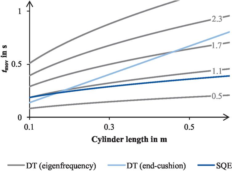
Figure 8 Comparison of the predicted movement times for an extension stroke of a cylinder with a diameter of 25 mm, a moving mass of 10 kg, and a supply pressure of 7 bar in SQE and downstream-throttled (DT) configuration.
3.1 Comparison with the Dimensioning of Downstream-Throttled Cylinders
This section compares the dimensioning method for pneumatic cylinders equipped with SQE valves with dimensioning methods of conventional downstream-throttled cylinders. The algebraic methods of Doll et al. [6] and Reese et al. [5] are used for the latter, because they follow a similar algebraic approach. The comparison highlights the fundamental differences between the novel and the conventional systems and clarifies the impact of the SQE valve on cylinder performance.
All calculations in this section refer to the extension stroke of a standard cylinder with a 25 mm piston diameter, a 10 kg moving mass, and a supply pressure of 7 bar. Nevertheless, the qualitative trends are valid for other cylinder sizes. The dead volume of the cylinders is neglected. Figure 8 shows the predicted movement time as a function of the stroke obtained with the different dimensioning methods. The movement time of the novel SQE system (dark blue) exhibits an approximately square-root dependence on cylinder length, close to a downstream-throttled cylinder with a PFR of one. In contrast, the downstream-throttled cylinder dimensioning method based on the end-cushion predicts that the PFR of downstream-throttled cylinders actually increases with stroke length, a finding that was experimentally confirmed in [5].
To clarify the similarities and differences Equation (19) can be rewritten in an analogous form to Equation (3) – the eigenfrequency method. Neglecting dead volumes yields an equivalent pneumatic frequency ratio (EPFR) , which expresses the ratio of the movement time of an SQE-equipped cylinder to the movement time based on the eigenfrequency method. The EPFR-value is obtained by coefficient comparison of Equation (3) and (22).
| (22) |
Figure 9(a) plots over cylinder length. For short cylinders is slightly above one, with increasing length it falls to slightly below one. Thus, the dynamics of an SQE-equipped cylinder lie closer to the theoretical minimal eigenfrequency compared to a downstream-throttled cylinder, which explains the considerable energy-saving potential already reported in [1].
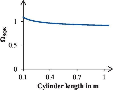
(a) Equivalent pneumatic frequency ratio
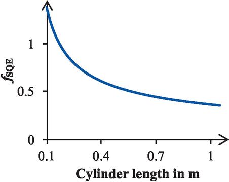
(b) SQE-factor
Figure 9 Difference of the novel dimensioning method for cylinders equipped with switchable quick-exhaust valves and dimensioning methods for downstream-throttled cylinders.
A coefficient comparison of the calculated movement time according to the novel sizing approach for systems with SQE with the movement time of a conventional downstream-throttled cylinder according to the sizing approach of Reese et al. is shown in Equation (23). It is obvious that the end-cushion capacity still appears in the SQE dimensioning formula, which is not surprising, because the end-cushion remains responsible for final deceleration. However, the velocity can no longer be assumed to be constant at the optimal entry velocity, so a factor is introduced. This factor represents the increase in velocity achieved by the SQE valve during the stroke relative to the optimal entry velocity and contains ratios of cylinder volume and supply pressure to end-cushion volume and pressure. The benefit of an SQE valve grows with increasing cylinder volume relative to the (essentially stroke independent) end-cushion volume. Figure 9(b) confirms this trend: decreases markedly with increasing stroke length, underscoring the valve’s potential, especially for long stroke lengths.
| (23) |
3.2 Simplified Dimensioning of Cylinders Equipped with SQE Valves
The eigenfrequency-based method of Doll et al. [6] is widely adopted in research and industry. As Section 3.2 demonstrates, the novel SQE sizing method follows a very similar trend with respect to stroke length. To facilitate industrial uptake of SQE technology, a simplified sizing rule is therefore proposed: apply Doll’s eigenfrequency method directly to SQE-equipped cylinders. Although this shortcut lacks strict physical derivation, assuming a PFR of one provides a satisfactory approximation, as Figure 9(a) shows. For medium and long strokes the movement time is slightly overestimated, yielding a conservative design. The accuracy of this simplified rule is evaluated in Section 4.
3.3 Impact on the Cylinder Dimensions
The dimensioning method for pneumatic cylinders equipped with SQE valves can be used to determine how the valves influence the required cylinder size. When a conventionally downstream-throttled cylinder is replaced by one with SQE valves, the same movement time can be achieved with a smaller piston diameter because of the higher achievable dynamics. Figure 10 illustrates this effect for a downstream-throttled cylinder with a 25 mm diameter. As the stroke length increases, the required diameter decreases. The corresponding standard diameter sizes are also shown in the figure. Starting at a stroke of 0.25 m, the use of SQE valves becomes advantageous, because at this length a 20 mm diameter cylinder is sufficient. This change alone reduces compressed air consumption by roughly 36% if dead volumes of the attached hoses and connectors can be neglected due to their small size in comparison to the cylinder chambers. The next smaller standard diameter (16 mm) can be selected at a stroke of 0.37 m, which cuts compressed air usage by approximately 59% compared with the downstream-throttled reference configuration.
In addition to the lower energy demand, using a smaller cylinder generally reduces acquisition costs. The extra cost of the SQE valves themselves must, however, be considered in the overall investment.
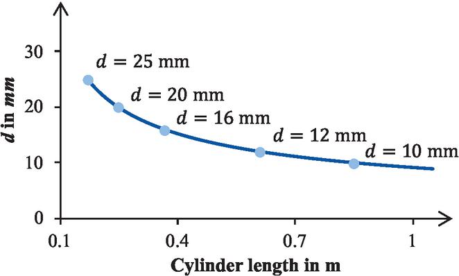
Figure 10 Required piston diameter of a cylinder equipped with switchable quick-exhaust valves to achieve the same movement time as a downstream-throttled cylinder with a diameter of 25 mm.
A practical challenge is that most commercially available cylinders are optimized for downstream throttling. The higher accelerations enabled by SQE valves impose larger loads on the piston rod while the diameter is smaller, so the critical buckling load can quickly be exceeded. Furthermore, many small-diameter cylinders are not offered with pneumatic end-cushioning or with long strokes, which limits the available options.
The proposed analytical dimensioning method can be summarized in the following design procedure. First, the desired movement time is specified based on the requirements of the motion task. Next, the minimum required downstream conductance is calculated using Equations (20) and (21) to verify that the selected directional control valve, downstream throttle, and quick-exhaust path provide sufficient flow capacity. Subsequently, the movement time is calculated for the considered cylinder diameter using Equation (19). Since the end-cushion geometry depends on the cylinder diameter, standard cylinder sizes are evaluated iteratively until the smallest cylinder satisfying the required movement time is identified. For applications requiring a simplified approach, the conventional eigenfrequency method with a pneumatic frequency ratio of approximately one provides a practical approximation for SQE-equipped cylinders.
4 Validation
The qualitative agreement between the motion model and the measured velocity is evident from the comparison of the measured velocity in Figure 5 with the motion model presented in Figure 6. Conversely, the quantitative validation of the novel dimensioning method and the proposed equations is conducted through an experimental investigation of the cylinder dynamics using the novel SQE valves. A total of nine cylinder geometries were tested with moving masses of 10 and 15 kg. The details of the experimental investigation and a discussion of the results are outlined in previous work [1]. Please note that the SQE valves used for cylinders with 32 mm in diameter do not satisfy the conductance criterion introduced in Section 3. Consequently, a discrepancy from the theoretically calculated movement time for these load cases is expected.
Figure 11 illustrates the discrepancy between the movement time calculated with the novel dimensioning method and the measured movement time . Because each cylinder geometry was tested with two moving masses and both the extension and retraction strokes were evaluated separately, a total of 36 measurement points are displayed. As shown, the calculated times for cylinders with 20 and 25 mm diameters lie within of 40 ms of the measured values. The maximum relative error is 9%. The method accurately predicts the movement time for both the extension and retraction strokes. As anticipated, the cylinders with a 32 mm diameter exhibit longer movement times than calculated, at least for longer stroke lengths, as predicted in Section 3 for flow-restricted operation.
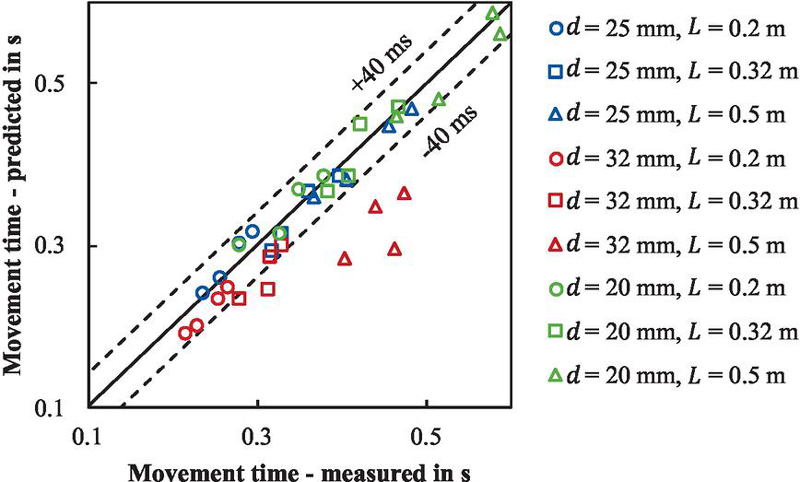
Figure 11 Comparison of the analytical estimations and the experimental results for the moving time of a cylinder equipped with a switchable quick-exhaust valve.
The expected error of the new method can be determined with the root-mean-squared error (RMSE):
| (24) |
where is the number of data points. Excluding the data for the 32 mm cylinders yields an RMSE of 17 ms. This substantiates the method’s validity and facilitates the estimation of the anticipated error.
Figure 12 shows the discrepancy between the movement times predicted with the eigenfrequency method and the measured times. Because that method does not distinguish between extension and retraction strokes, the mean value of both movement times was used for each load case. The results for the 20 and 25 mm cylinders cluster tightly, corresponding to PFR values between 0.9 and 1.1. As expected, the 32 mm cylinders display higher PFR values. The method’s precision and simplicity enable reliable sizing via the simplified dimensioning procedure. Nevertheless, it is advisable to select a PFR of at least 1.1 during design to compensate for possible friction forces. Setting the value much higher should be avoided, as it would negate the energy savings achieved with SQE valves.
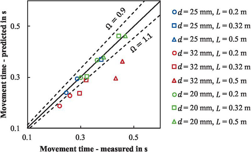
Figure 12 Comparison of the predicted moving time based on the eigenfrequency method with a pneumatic frequency ratio of one and the experimental results for the average moving time of the extension and retraction stroke of a cylinder equipped with switchable quick-exhaust valves.
The novel dimensioning method considers only movement time, whereas the cycle time comprises both delay time and movement time. With short pneumatic lines, the delay time caused by pressure equalization, described by Reinertz et al. [4], can be neglected, because the quick-exhaust active at stroke onset accelerates pressure adaptation in comparison to a downstream-throttled system. For long pneumatic lines, however, transient effects and the altered switching behavior of the SQE valves must be considered, as they can cause larger deviations from the theoretical cycle time [1].
4.1 Dimensioning of the SMC Deceleration Controller
To demonstrate the applicability of the proposed dimensioning method to commercially available energy-saving concepts, the analytical model was validated using the SMC Deceleration Controller (DAS), shown in Figure 13. Unlike the custom SQE valve investigated in the previous section, the DAS integrates the switching function and downstream throttling into a single commercial component.
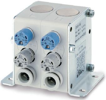
Figure 13 SMC deceleration controller DAS5-06.
Two DAS variants were investigated. According to the manufacturer’s datasheet, the DAS5-x series is recommended for cylinder diameters between 10 and 40 mm, whereas the DAS7-x series is intended for cylinders up to 100 mm [14]. Since the investigated cylinders (20 mm and 25 mm) fall within the specified range of both variants, the experiments allow the influence of the available valve conductance on the applicability of the proposed dimensioning method to be evaluated.
Two DAS variants were investigated. According to the manufacturer’s datasheet, the DAS5-x series is recommended for cylinder diameters between 10 and 40 mm, whereas the DAS7-x series is intended for cylinders up to 100 mm [14]. Since the investigated cylinders (20 and 25 mm) fall within the recommended application range of the DAS5-x series, this valve was initially selected for the experiments. However, as shown below, its available conductance becomes insufficient for the highly dynamic operating conditions considered in this work. To investigate the influence of valve conductance, the experiments were therefore repeated using the larger DAS7-08, whose higher conductance satisfies the proposed conductance criterion.
Figure 14 shows the results obtained with the DAS5-06. While good agreement is achieved for short strokes, the prediction error increases with increasing cylinder volume. This trend indicates that the available conductance of the DAS5-06 becomes insufficient for the highly dynamic operating conditions considered in this work. Although the valve is dimensioned appropriately for conventional deceleration applications, its conductance limits the achievable cylinder dynamics when it is used to significantly increase the piston velocity for energy-efficient cylinder downsizing. Consequently, the movement becomes flow-limited and the analytical model systematically underestimates the movement time, exactly as predicted by the conductance criterion introduced in Section 3.
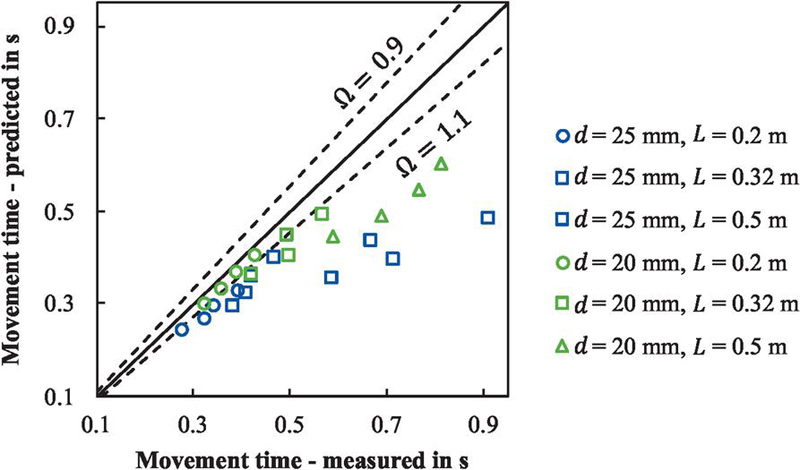
Figure 14 Comparison of the analytical estimations and the experimental results for the moving time of a cylinder equipped with the SMC Deceleration Controller DAS5-06.
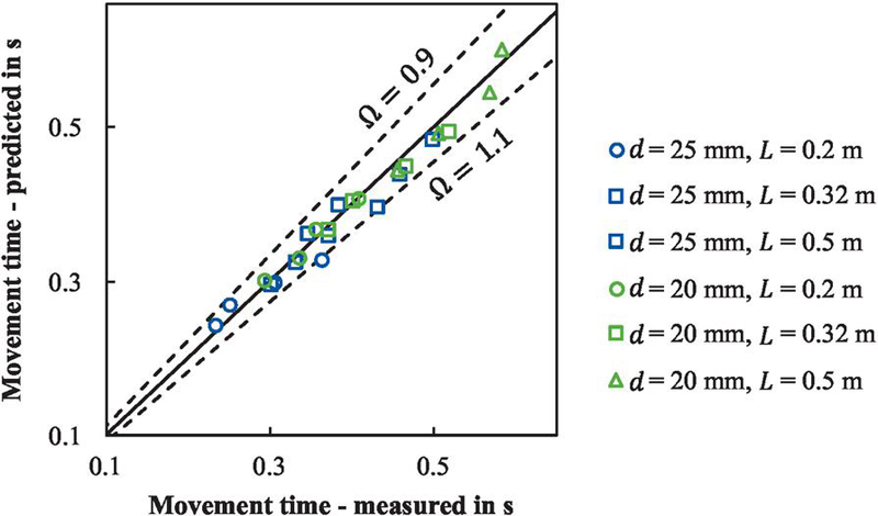
Figure 15 Comparison of the analytical estimations and the experimental results for the moving time of a cylinder equipped with the SMC Deceleration Controller DAS7-08.
To verify this hypothesis, the measurements were repeated using the larger DAS7-08, which provides a substantially higher conductance while operating according to the same functional principle. The corresponding results are shown in Figure 15. In this case, all measurements lie between equivalent PFR values of 0.9 and 1.1, yielding an average prediction error of 3.4% and a maximum error of 9.2%. The excellent agreement confirms that the proposed analytical dimensioning method is applicable not only to the custom SQE valve but also to commercially available systems, provided that the available valve conductance satisfies the criterion proposed in Section 3.
Together with the validation of the custom SQE valve presented in Section 4, these results demonstrate that the proposed analytical dimensioning method accurately predicts the dynamics of both custom and commercially available time-controlled downstream-throttled energy-saving circuits, provided that the conductance criterion is fulfilled.
5 Summary and Conclusions
This paper presented a novel analytical dimensioning method for inertial pneumatic motion tasks using SQE valves. Based on a simplified movement model, an algebraic equation for predicting the movement time was derived. Furthermore, a minimum conductance criterion was introduced to define the applicability range of the analytical model and to verify that the cylinder dynamics are governed by pneumatic stiffness rather than by flow limitations. Experimental validation over a wide range of operating conditions demonstrated high prediction accuracy. In addition, a simplified dimensioning rule based on the eigenfrequency method was proposed to facilitate industrial application. The method was successfully validated for both the developed SQE valve and the commercially available SMC Deceleration Controller, demonstrating its applicability to time-controlled downstream-resistance concepts in general.
Future work should extend the method to include the entire cycle time, accounting for pressure-build-up transients and the unstable switching behavior of SQE valves in long pneumatic lines. Moreover, incorporating external forces into the sizing equations would further broaden the method’s applicability. A challenge for the implementation of this new technology will be the smaller rod diameter in combination with a higher dynamic load, which can exceed the buckling load of the cylinder rod. Also, the availability of cylinders with a small piston diameter, high stroke lengths and pneumatic end-cushioning is still limited.
Acknowledgement
The research and development project S-LEAP – Quick-Exhaust for increasing the performance and efficiency of exhaust throttled pneumatic drives – is funded by the European Union and the state of North Rhine-Westphalia within the framework of the European Regional Development Fund (EFRE), grant number EFRE-20800048.

References
[1] L. Päßler, C. Reese, O. Reinertz, and K. Schmitz, “Implementation and Experimental Validation of a Time-Controlled Quick-Exhaust for Downstream Throttled Pneumatic Drives,” Fluid Power 2025, Maribor, Slovenia, 2025.
[2] V. Boyko, F. Nazarov, W. Gauchel, R. Neumann, M. Doll, and J. Weber, “Comprehensive Application-Based Analysis of Energy-Saving Measures in Pneumatics,” International Journal of Fluid Power, vol. 25, no. 1, pp. 27–58, 2024.
[3] V. Boyko, S. Hülsmann, and J. Weber, “Comparative Analysis of Actuator Dimensioning Methods in Pneumatics,” in ASME/BATH 2021 Symposium on Fluid Power and Motion Control, Bath, United Kingdom, 2021.
[4] O. Reinertz and K. Schmitz, “Optimized Pneumatic Drives Through Combined Downstream and Adaptive Upstream Throttling,” in BATH/ASME 2020 Symposium on Fluid Power and Motion Control, Bath, United Kingdom, 2020.
[5] C. Reese, O. Reinertz, and K. Schmitz, “Dimensioning method of pneumatic cylinders based on the pneumatic end-cushion,” International Journal of Fluid Power, vol. 26, no. 3, pp. 381–410, 2025.
[6] M. Doll, R. Neumann, and O. Sawodny, “Dimensioning of pneumatic cylinders for motion tasks,” International Journal of Fluid Power, vol. 16, no. 1, pp. 11–24, 2015.
[7] D. Gryboś and J. S. Leszczyński, “A Review of Energy Overconsumption Reduction Methods in the Utilization Stage in Compressed Air Systems,” Energies, vol. 17, no. 6, p. 1495, 2024.
[8] D. Scholz, Auslegung servopneumatischer Antriebssysteme. Aachen, Germany: Dissertation RWTH University, 1990.
[9] K. Schmitz and O. Reinertz, “Pneumatikantrieb, Entlüftungsventil dafür und Verfahren zum Entlüften,” Aachen, Germany Patent DE102023104570B3, Feb. 24, 2023.
[10] M. Doll, R. Neumann, and O. Sawodny, “Energy efficient use of compressed air in pneumatic drive systems for motion tasks,” in Proceedings of 2011 International Conference on Fluid Power and Mechatronics, FPM 2011, Beijing, China, 2011.
[11] O. Reinertz, C. Reese, and K. Schmitz, “Downstream Throttled Pneumatic Drives with Time-Controlled Pneumatic-Mechanical Quick-Exhaust Valve,” in Proceedings of the 2024 Global Fluid Power Society PhD Symposium (GFPS), Hudiksvall, Sweden, 2024.
[12] A. Nishimura, H. Yamada, and K. Fukushima, “Durchflussregler und Atnriebsvorrichtung damit,” Patent EP 3 891 402 B1, Oct. 13, 2021.
[13] A. Nishimura and A. Tadano, “Time delay valve and flow rate controller,” Patent EP 4 163 503 B1, Apr. 12, 2023.
[14] SMC Corporation, Operation Manual Deceleration Controller DAS. Available: https://www.smcworld.com/upfiles/manual/en-jp/files/DOC1018150.pdf, [Accessed: Feb. 5, 2026].
[15] S. Merkelbach and H. Murrenhoff, “Exergy Based Analysis of Pneumatic Air Saving Measures,” in Proceedings of the ASME/BATH 2015 Symposium on Fluid Power and Motion Control (FPMC2015), Chicago, USA, 2015.
[16] M. Y. Mohd Yusop, Energy Saving for Pneumatic Actuation using Dynamic Model Prediction. Wales, United Kingdom: School of Engineering, Cardiff University, 2006.
[17] P. Harris, G. E. O’Donnell, and T. Whelan, “Energy Efficiency in Pneumatic Production Systems: State of the Art and Future,” in Leveraging Technology for a Sustainable World, Berlin, Heidelberg, Germany, 2012.
[18] A. Raisch, S. Hüllsmann, and O. Sawodny, “Saving Energy by Predictive Supply Air Shutoff for Pneumatic Drives,” in 2018 European Control Conference (ECC), Limassol, Cyprus, 2018.
[19] P. Harris, S. Nolan, and G. E. O’Donnell, “Energy optimisation of pneumatic actuator systems in manufacturing,” Journal of Cleaner Production, vol. 72, pp. 35–45, 2014.
[20] Y. Shi, X. Li, and Y. Teng, “Research on Pneumatic Cylinder’s Exhausted-Air Reclaiming Control Devices,” in Proceedings of the JFPS International Symposium on Fluid Power, Tsukuba, Japan, 2005.
[21] C. Reese, O. Reinertz, and K. Schmitz, “Feasibility Study and Experimental Validation of a Novel Combined Throttling Approach,” in 14th International Fluid Power Conference (14. IFK), Dresden, Germany, 2024.
[22] M. Guelker, “White Paper – Innovative air cushion solution improves productivity and machine reliability and saves money,” Festo Corporation, 2011.
[23] P. O’Neill, “All About Cylinder Cushioning,” Power and Motion, 2006.
[24] F. Tröster and H. Geupel, Steuerungs- und Regelungstechnik für Ingenieure. München, Germany: Oldenbourg Wissenschaftsverlag, 2005.
Biographies

Luca Päßler received a bachelor’s degree in mechanical engineering in 2022 and a Master’s degree in process engineering from RWTH Aachen University in 2024. Since 2024, he has been working as a research associate at the Institute for Fluid Power Drives and Systems (ifas), RWTH Aachen University. His research areas include simulation and optimization of pneumatic systems and components, focusing on enhancing energy efficiency and performance.

Olivier Reinertz received his diploma and his doctoral degree in mechanical engineering from RWTH Aachen University, Germany. He is currently Scientific Director at the Institute for Fluid Power Drives and Systems (ifas) at RWTH Aachen University and since 2025 adjunct professor at RWTH Aachen University. His research focuses on the model-based analysis of fluid power components and systems and the derivation and validation of innovative strategies for efficiency and performance optimization with an emphasis on compressed air and gas-powered systems.

Katharina Schmitz studied mechanical engineering at RWTH Aachen University and Carnegie Mellon University in Pittsburgh (USA) and graduated as Dr.-Ing. at RWTH Aachen University in 2015. Since 2018, she is a full professor at RWTH Aachen University and director of the Institute for Fluid Power Drives and Systems (ifas). In addition, she is Vice Dean of the Faculty for Mechanical Engineering at RWTH Aachen, a position she has held since 2020. Prof. Schmitz’s awards and honours include several best paper awards and 2023 IMechE Joseph Bramah Medal award.
International Journal of Fluid Power, Vol. 27_3, 617–648
doi: 10.13052/ijfp1439-9776.2736
© 2026 River Publishers