Development of a Dual Supply H-Bridge Amplifier for High Speed Actuation of Digital Hydraulic Switching Valves
Florian Messner* and Rudolf Scheidl
Institute of Machine Design and Hydraulic Drives, Johannes Kepler University, Linz, Austria
E-mail: florian.messner@jku.at
*Corresponding Author
Received 04 February 2019; Accepted 06 May 2019; Publication 18 May 2019
Abstract
For many digital hydraulic systems, fast and precise valve actuation is a key to improve efficiency and performance. Such an actuation may be achieved by optimizing the valve design from a mechanical and hydraulically point of view. But additionally, power electronics for valve actuation has to be given also high attention since it can have significant influence on valve dynamics, particularly in case of high-speed actuation with switching times in the range of 1 ms or less. Such actuation poses requirements that are not met by standard power electronics. These requirements are analysed in this paper and a proper schematic for the power electronics is derived. Measurements with a corresponding prototype prove that a fast, precise and very repeatable valve actuation can be achieved if the power electronics is conceived according to the characteristics of high speed valves.
Keywords: Digital hydraulics; fast switching valves; high-speed valve actuation; power electronics; logic controller.
Introduction
The main idea of digital hydraulics consists of the replacement of traditional servo valves or proportional valves with binary operating switching valves in combination with an appropriate control strategy. Thus, switching valve related advantages like robustness, leakage-free valve design, less sensitivity to wear and others may be introduced to the hydraulic system.
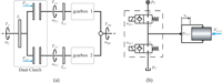
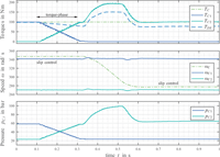
According to Linjama (2011) digital fluid power may be classified into three different fields: On-off methods, switching methods, and parallel technologies. In many cases, marketable valves cannot properly meet the system requirements in order to fulfil performance or cost criteria. This circumstance forced many digital fluid power research groups to develop proper valves for their specific digital systems. The realization of digital displacement machines, a representative of parallel technologies and first introduced by Artemis (Ehsan et al., 2000), requires high flow rate and fast switching valves as well as precise timing to accomplish the desired high efficiency in part load conditions. Research on and development of such valves has been thoroughly reported by the research group at Aalborg University in the last years (see for instance Roemer et al., 2014, Nørgård et al., 2016). The proper functioning of parallel valve technology for flow control by so called digital flow control units (DFCUs), intensively investigated by the digital fluid power group at Tampere University of Technology, turned out to depend on precise timing of the valves in order to achieve a smooth operation, particularly if a binary coding concept is applied (Laamanen et al., 2007). Consequently, this group tackled the development of proper valves to realize DFCUs (Uusitalo et al., 2007). In hydraulic switching control valves are repeatedly switching with high frequencies to obtain a high control bandwidth or to realize switching converters with an acceptable size (Brown et al., 1988, Scheidl et al., 1995, Pan et al., 2017). An application of hydraulic switching control, which triggered the research reported in this paper, is the hydraulic actuation of an automotive dual-clutch system (Messner and Scheidl 2016) by quite a simple concept, as sketched in Figure 1. The pressure pc1,2 in the chamber of a plunger cylinder is controlled by two fast on/off valves. The actuator has two basic modes of operation: (i) The actuation or release modes, to engage clutch from its released state or to disengage it; (ii) the slip control mode, where the clutch transfers the torque but not in a tight way but with some slip, in steady state operation typically a few rpms. During gear shift the slip of the two clutches is continuously changed, increased by the disengaging and decreased by the engaging clutch. This is also known as the so-called Torque-phase where the engine torque is transferred from one clutch to the other. The smoothness of pressure control is essential for an accurate engagement and for slip control. Figure 2 is depicting the results of a corresponding simulation study.
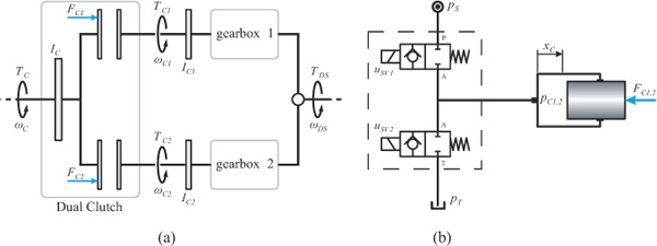
Figure 1 (a) Basic layout for a dual-clutch system with two gearboxes and clutch actuation forces FC1 and FC2 resp.; (b) Hydraulic clutch actuation concept using two switching valves and a plunger cylinder.
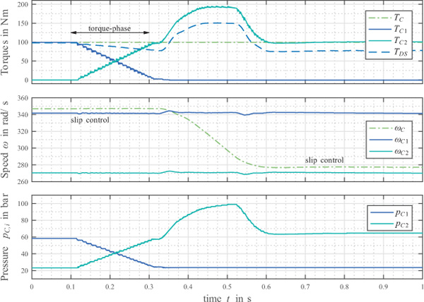
Figure 2 Simulation of a dual-clutch system actuated using the hydraulic concept in Figure 1; Torque-phase (t = 0.1... 0.3 s) for transferring input torque Tc from clutch 1 to clutch 2; Inertia-phase (t = 0.35 ... 0.6 s) for change in engine speed.
For being able to experimentally investigate the performance gains that may be accomplished using a very fast valve, a prototype valve sized according to the very small flow rates needed in such a clutch application was developed. It employs a high end solenoid used for diesel common rail injection which actuates a ball type seat valve. Its design and performance have been reported (Messner and Scheidl 2016, additional parameters are listed at the end of the paper in Table 3). At first, a power electronic circuit developed for electrical drives was applied to control the solenoid current. However, it turned out that this circuit was not able to control the full performance range of the solenoid, for several reasons. Its low internal dynamics caused considerable delay, boosting was not supported and the PWM-input duty-cycle had to stay above 0.05 in order to avoid discharge of an internal driver circuit. As a consequence, first switching commands after some period of inactivity (order of 1 second) did not lead to a proper switching of the valve as Figure 3 is showing.
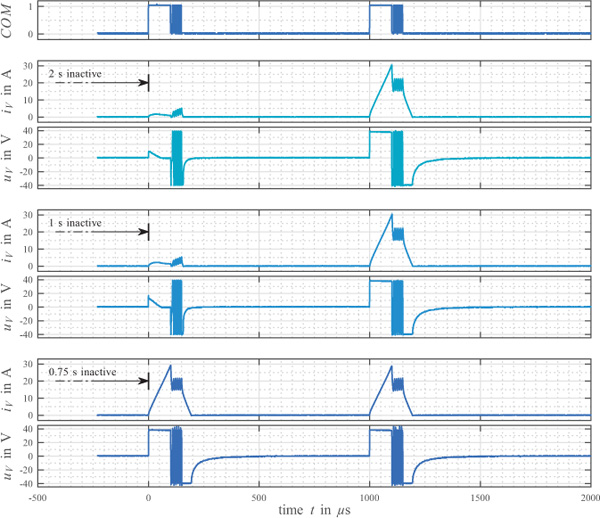
Figure 3 Valve actuation failure for different periods of inactivity using inappropriate power electronics. First actuation fails if valve is inactive for longer than 0.75 seconds due to discharge of internal driver circuits.
The majority of the published work on fast switching valves addresses the actuator part, typically some solenoid or some hydraulic piloting, the mechanical design, specific problems of cushioning or fluid stiction and their solution by proper mechanical design or control concepts. By far less is published about power and control electronics. Several simulation studies deal with the use of a higher voltage level (boost-voltage) at the beginning of the valve actuation in order to speed up the actuation process (Kallenbach et al., 2003). However, there is very little accessible information about a specific schematic layout for such electronics. Linjama (2015) reports about the development of electronics for very compact valve blocks with up to 128 valves in parallel. Consequently, this huge number of paralleled valves increases demands on the compactness of the power electronics. Li et al. (2017) are conducting a simulation study on high-speed valve actuation using two supply voltage levels. Commercially available electronics are – for reasons of confidentiality – usually not documented in detail and mostly developed for a specific valve model (Bosch Rexroth 2012).
According to literature, high-speed valve actuation is not solely a topic in digital hydraulics. Other fields of application are suffering from an even stronger urge to push valve dynamics further towards its limits. Common rail injection for combustion engines is an excellent example, since the required response times in the order of only some hundred microseconds pose high demands on the power electronics. The actuation scheme for such an injector is stated (Reif 2011 and 2015, Robert Bosch GmbH 2010 and 2016) to be separated into different periods of actuation, but there is no detailed information about a specific schematic layout for the power electronics.
The paper at hands deals with the development of power electronics for high-speed valves overcoming the limitations of the existing device, as stated above. The basic layout of the proposed electronics resembles the well-known H-bridge design. Additionally, it provides two different supply voltage levels. The combination of these two characteristics suggests entitling it a Dual-Supply H-bridge Amplifier (DSHA).
The next section of this paper gives a short introduction to the basic requirements and circuit concepts of power electronics for switching valve actuation. Afterwards, the desired trajectory for the valve current feed is presented and the corresponding requirements on the power electronics are discussed. This is followed by the schematics for the proposed power electronics. Subsequently, a logic controller is introduced which avoids destructive modes of operation, a crucial safety issue. Finally, some results and measurements showing an exemplary actuation of a valve are summed up and a conclusion is drawn.
Power Electronic Basics for Switching Valve Actuation
Fundamental Power Electronics
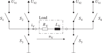
Typically, power electronics for solenoid valve actuation is quite simple. In general, top level of complexity of the most central part may be represented by an H-bridge design as depicted in Figure 4(a), incorporating four electronic switches S1 to S4. This design allows for a change in voltage direction and consequently also for a change in the direction of the magnetic field. However, as the armature forces, if they are Maxwell forces, are not depending on the direction of the magnetic field, this design seems to exceed the requirements for the majority of applications. Thus, most of the commonly used actuation concepts are based on the much simpler schematics in Figure 4(b) and 4(c), both of them including a reduced number of electronic switches.
The so-called phase-leg in Figure 4(b) consists of one half of an H-bridge. It enables connecting the valve solenoid to either supply voltage or ground. Powering the solenoid is achieved using the high-side (HS) switch, freewheeling with the low-side (LS) switch. If neither of these switches is activated, additional components may be needed for voltage surge protection. The structure in Figure 4(c) simply consist of a single HS-switch (LS-switch-setup also very common), offering only two possible states of operation.
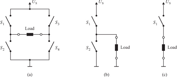
Figure 4 Simplified schematics for valve actuation using (a) an H-bridge design, (b) a phaseleg design and (c) a single high-side switch.
The solenoid is energized by activating the switch and de-energized using additional freewheeling components.
Both schematics may be controlled by pulse-width-modulation (PWM), which is a simple control approach with one control parameter – the duty cycle.
Advanced Power Electronics
In the last years, motivated by the deficiencies listed previously, power electronics for valve actuation developed towards a slightly more sophisticated setup. The main schematics still resemble the structures in Figure 4(b) and 4(c), but an initial phase of valve actuation is performed at an increased voltage level, the so-called the ‘boost-voltage’. The fundamental idea behind this is to speed up the actuation process by creating a steeper current slope at the beginning. For the majority of implementations this is realized using a preloaded capacitor (Linjama et al., 2015). As a drawback actuation frequency may be limited due to the required capacitor reload interval (Bosch Rexroth 2012). Furthermore, capacitor size has to be chosen appropriately to the valve in use. Consequently, if valve parameters change or a different valve is used, a corresponding change in electronics is needed. Another study, conducted by Li et al. (2017), is dealing with the use of two individual supply voltage levels, eliminating the need for a boost-capacitor. The corresponding simulations are also stating an improved valve dynamics.
Proposed Power Electronics for High-Speed Actuation
Valve Current Feed Sequence
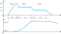
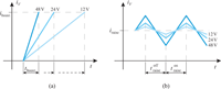
The main objective of the boost-period is a fast build-up of the magnetic field, which in turn will cause forces on the valve armature, initiating a movement of the armature (position sV). Neglecting eddy currents, the magnetic field correlates with the valve current iv. Thus, the demand for a fast build-up of the magnetic field actually breaks down to the requirement for a very steep current slope. Consequently, the boost-period is always clearly distinguishable from the rest of the valve actuation, due to its steep current inclination up to an excessive level iboost as depicted in Figure 5.
On the contrary, the main focus of the subsequent raise-period is to keep the valve current on a more or less constant, but still elevated level iraise, in order to create a force close to the solenoids limits for maximizing valve armature acceleration. The valve is said to be raised towards a completely opened position (see Figure 5). Sometimes this period is also referred to as tightening-period or pull-in-period. Fast fluctuations of the valve current (so-called current ripple) will cause eddy-currents and magnetic hysteresis, both wasting energy and increasing solenoid heat up. Therefore, current should be kept as constant as possible.
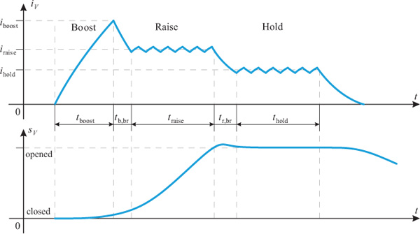
Figure 5 Desired valve current feed showing boost, raise and hold-period and the corresponding armature stroke.
Finally, once the upper position is reached, the valve simply has to be kept open (hold-period). As there is no more need for further valve acceleration the solenoid force only needs to balance the return-spring force and, if present, flow forces. Hence, the valve current may be reduced to a lower level ihold sufficient to hold the valve armature in the open position. Typically, such a hold phase is applied if thermal loading of the solenoid is critical.
Consequences for Power Electronics
Assuming an operation far-off from steady state of the valve current iv, the current slope is given by Equation (1).
This simply means, that there are only two options for a fast increase of iv while boosting: higher voltage uv or lower inductance Lv. The inductance of a solenoid depends on solenoid geometry, material parameters, and – strongest – on the coil winding number. Higher winding numbers reduce the required valve currents to generate a certain magnetomotive force. Thus, maximum current and inductivity are a trade-off pair, leaving no freedom for reducing inductance, if current is fixed. Hence, high current slopes require a high voltage uv. Figure 6(a) is visualising the change in the current slope for different values of uv. Obviously, a demand for higher valve dynamics inevitably results in the need for higher boost voltage.
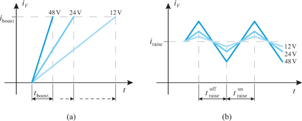
Figure 6 (a) Current slope while boosting and (b) current ripple during raise and hold for different supply voltages.
As already mentioned, the raise-period is aiming for a constant current level in order to minimize eddy-currents. If effective voltage is controlled by switching between supply voltage or ground, e.g. in a PWM fashion, the valve current cannot be kept completely constant but has a saw-tooth-like current pattern as shown in Figure 6(b). The current ripples can be kept low with a high switching frequency, which is the inverse of the sum of and , or a low supply voltage. Factually, for typical data of valve solenoids and a high voltage adequate for valve boosting, satisfactory current ripple may require switching frequencies in the range of 100 kHz and beyond. Such frequencies are posing even higher demands on the timing of the power electronic circuits and might cause severe electromagnetic compatibility (EMC) problems due to the high currents. Thus, a single voltage source cannot solve this trade-off problem.
The hold-period differs from the raise-period only with respect to the current level, which is slightly lower.
The transition between the different periods is important for timing purposes, thus, the change from one period to the next should be as fast as possible. This can be done by a reverse voltage being connected to the solenoid, preferably the reversed supply voltage.
A fast change between different periods or different states of operation is only possible if the electronic components – particularly the ‘electronic switches’ (MOSFETs) – are also offering a very high timing precision. Switching times for these kind of components are typically in the range of some hundred nanoseconds. In order to realize a fast, but still stable, precise and reproducible behaviour for a change in the power electronics mode of operation, a timing precision of 1 μs or less for the entire electronic setup is necessary.
In conclusion, the following requirements for the power electronics have to be met:
- Connection to a high supply voltage during boost-period in order to reduce boost duration tboost
- Connection to a low supply voltage during raise- and hold-period in order to reduce current ripple
- Reverse voltage while changing from one period to the next, preferably at level of higher supply voltage
- Reverse voltage during raise- and hold-period, preferably at lower supply voltage
- Additionally, a disconnection of the solenoid as well as freewheeling must be possible
- For timing reasons, a change in state of operation in 1 μ s or less has to be realized.
The above list leads to six essential ways of connecting the solenoid. It’s quite obvious, that this cannot be realized with one of the basic schematics shown in Figure 4.
Final Power Electronic Schematics
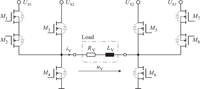
Extending the H-bridge design in Figure 4(a) by two additional HS-switches leads to the schematics in Figure 7. This setup can provide all six required modes of operation. A corresponding schematic layout incorporating real electronic switches in terms of n-channel MOSFETs M1 to M8 is depicted in Figure 8. Due to the presence of two different power supply levels US1 and US2, this setup is referred to as dual-supply H-bridge amplifier (DSHA).
A closer look reveals that the setup in Figure 8 consists of more MOSFETs than there are switches in Figure 7. This is due to the necessary short-circuit-protection between the higher supply voltage US2 and the lower supply voltage US1. Without MOSFETs M2 and M8 an activation of either M3 or M5 would result in the body diodes of M1 or M7 becoming conductive and short-circuiting US2 and US1. The arrangement of M1 ,M2 and M7 ,M8 respectively, is commonly known as ‘back-to-back’ configuration and usually used for bidirectional control (Panguloori 2017).
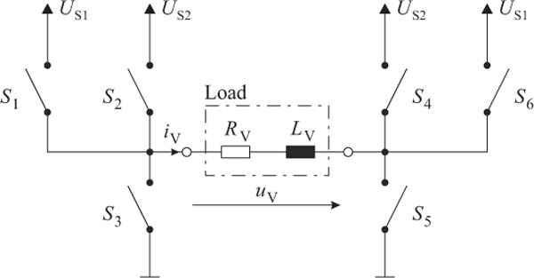
Figure 7 Simplified schematics for the proposed power electronics, extending a standard H-bridge design by switches S1 and S6.
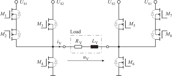
Figure 8 Final setup for the power electronics composed of n-channel MOSFETs.
The setup in Figure 8 is not showing the entire schematics designed during DSHA-development. Additional circuits have been implemented. For example, activation and deactivation of MOSFETs M1 to M8 is usually realized using appropriate gate driver circuits (International Rectifier 2007, Specovius 2015, Balogh 2017). Furthermore, DSHA-design has been enhanced for a shoot-through-protection in order to minimize short-circuit-current in case of an unintentional overlapping of high- and low-side activation. Additionally, current sensors installed in the main power-lines render an overcurrent-detection as well as a corresponding overcurrent-shutdown circuitry possible.
For lack of space and as they are not necessarily needed for understanding of the DSHA, these circuits are not presented in this paper.
Logic Controller
The schematics in Figure 7 or Figure 8 are clearly demonstrating that simultaneous activation of specific MOSFET combinations (for example activation of M3 and M4) will result in destruction of the circuit board or at least a severe damage of components. Therefore, this kind of actuation failure has to be eliminated. Considering the required timing accuracy for a change in the output of the electronics as stated above, the situation is becoming even worse. Better timing is only possible with a faster transition of the MOSFETs – typical values for such a transition are in the range of some hundred nanoseconds. Unfortunately, this also means increased requirements upon the timing accuracy of the input signals, as even short-time errors will lead to an undesired behaviour. For instance, if one of the signals driving the MOSFETs is being delayed for only a few microseconds (e.g. caused by signal delay in the external wires, an asynchronous behaviour of the sources driving the signals or simply a software error of the real-time system), then the combination of all input signal may represent an undesired configuration for the time of delay. An example for such an undesired configuration may be the simultaneous actuation of MOSFETS M3 and M4. As a consequence, there will be a low-resistive connection between US2 and ground, short-circuiting the power supply. This situation is called a shoot-through. In order to eliminate such risks, a logic controller allowing only for specific modes of operation and capable of the required timing precision is highly recommended.
Furthermore, a faster MOSFET transition also means an increased risk for shoot-through, when high- and low-side FETs are changing their states simultaneously, as transitions may overlap (for example when changing from forward to reverse boost-voltage). This may be compensated by the logic controller using a specific sequence for MOSFETs being turned on and off. However, this problem can be solved easier using gate resistors and diodes acting as time delays or gate driver circuits allowing for an adjustable delay between high and low-side transition. Therefore, overlapping related shoot- through is not considered to be part of the logic controller design.
Modes of Operation
Due to the requirements stated above, there’s a need for specific modes of operation. These modes are represented by a set of Boolean values for all eight MOSFETs M1 to M8 (referred to as gate-signals), indicating either an active (logic 1) or inactive (logic 0) state. For example, if the solenoid is supposed to be connected to the higher supply level US2, MOSFETs M3 and M6 have to be activated, but the rest has to remain inactive. Furthermore, as the design in Figure 8 is allowing for a change in voltage direction, any connection realizing a voltage direction similar to the activation of M3 and M6 will be referred to as ‘forward’, any connection leading to an inverted voltage direction will be referred to as ‘reverse’.
The implemented modes of operation in combination with the corresponding gate-signals are listed in Table 1. The previously mentioned number of six different ways to connect the solenoid is extended to a total number of eight modes. This is caused by the use of Boolean signals serving as inputs for the logic controller, encoding the modes of operation. For a proper encoding of six different states, at least three Boolean input signals COM1 to COM3 are needed. However, three Boolean signals are offering a total of eight distinguishable states. In order to prevent any malfunction due to the inputs encoding to an ‘unused’ state, Table 1 has been extended by two additional modes of operation: free-wheeling with US1 active and a default mode, also with US1 active.
The Boolean signals COM1 to COM3 are acting as inputs, meaning that the user has to prepare for an appropriate signal source, capable of the timing requirements. The logic controller is scanning these inputs using an internal clock rate of 25 MHz and decoding the corresponding gate-signals according to Table 1.
Table 1 Allowed modes of operation
| Inputs | Gate-Signals | ||||||||||
|---|---|---|---|---|---|---|---|---|---|---|---|
| COM1 | COM2 | COM3 | Modes of Operation | M1 | M2 | M3 | M4 | M5 | M6 | M7 | M8 |
| 0 | 0 | 0 | Default; All FETs off; US1 inactive | 0 | 0 | 0 | 0 | 0 | 0 | 0 | 0 |
| 0 | 1 | 0 | Free-wheeling; US1 inactive | 0 | 0 | 0 | 1 | 0 | 1 | 0 | 0 |
| 1 | 0 | 0 | Default; US1 active | 0 | 1 | 0 | 0 | 0 | 0 | 0 | 1 |
| 1 | 1 | 0 | Free-wheeling; US1 active | 0 | 1 | 0 | 1 | 0 | 1 | 0 | 1 |
| 0 | 0 | 1 | Active; Reversed voltage US2 | 0 | 0 | 0 | 1 | 1 | 0 | 0 | 0 |
| 0 | 1 | 1 | Active; Forwarded voltage US2 | 0 | 0 | 1 | 0 | 0 | 1 | 0 | 0 |
| 1 | 0 | 1 | Active; Reversed voltage US1 | 0 | 1 | 0 | 1 | 0 | 0 | 1 | 1 |
| 1 | 1 | 1 | Active; Forwarded voltage US1 | 1 | 1 | 0 | 0 | 0 | 1 | 0 | 1 |
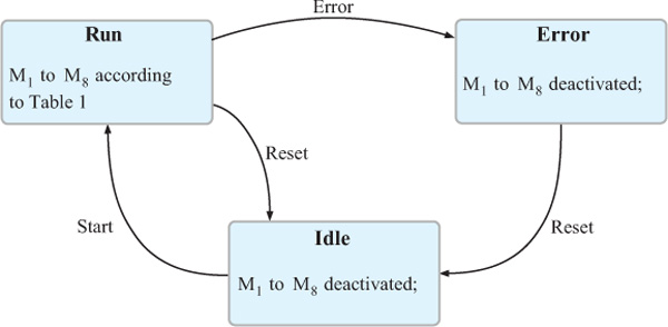
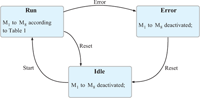
Figure 9 Developed state machine for the logic controller.
Using 25 MHz as internal clock rate means that the logic controller is capable of reacting to a change in input signals within 40 ns. In combination with the transition time of the MOSFETS (some hundred nanoseconds), this enables the electronics to change its state in less than a microsecond.
State Machine
The logic controller is implemented as a simple state-machine setup with three different states: Idle, Run and Error as depicted in Figure 9.
The state-machine generally starts up in Idle-state, with gate-signals M1 to M8 deactivated. Idle-state can only be changed to Run-state, if the start-button is pressed (user input needed for safety reasons). During Run-state gate-signals M1 to M8 are set according to Table 1. Run-state is exited either if the user presses the reset-button or if any of the error-inputs is activated by the overcurrent-detection circuitry. Error-state is very similar to Idle-state with all the MOSFETs deactivated. Additionally, for sake of user information, some LEDs are lightened. The only way of exiting Error-state is to press the reset-button.
Results
The results presented in this paper are divided into two main parts. The first part is briefly describing the final design, including printed circuit board (PCB) and housing. The second part is dealing with measurements verifying the proposed operation of both, the logic controller and the power electronics.
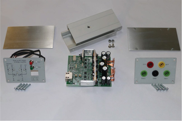
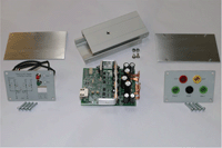
Figure 10 Disassembled DSHA with PCB and housing components.
Final Design
Figure 10 is showing the final components of the DSHA in a disassembled state. On the left side the front panel is visible. It incorporates all user-interface related elements, for example, LEDs visualizing the current state-machine state or any overcurrent occurrence. Furthermore, push-buttons serving as user-feedback (start and reset-button) for the logic controller are placed at the front panel.
The final PCB is located in the middle of Figure 10. The power electronics is located on its right side, recognizable by the big smoothening capacitors, the copper connectors and the aluminium sheet metal used as heat sink.
The logic controller is implemented as a complex programmable logic device (CPLD). Being located at the bottom side of the PCB, it’s not visible in Figure 10.
Figure 11 is showing the DSHA in its final assembled state.
Measurements
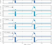
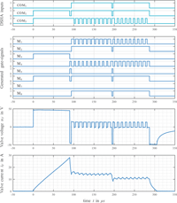
Figure 12 is showing the results for a single valve actuation applying an entire boost-, raise- and hold-sequence as proposed in Figure 5 on a real valve acting as load (for valve details see Messner and Scheidl 2016). The corresponding timing parameters for this measurement are listed in Table 2. Additionally, supply values as well as some valve parameters are given in Table 3.
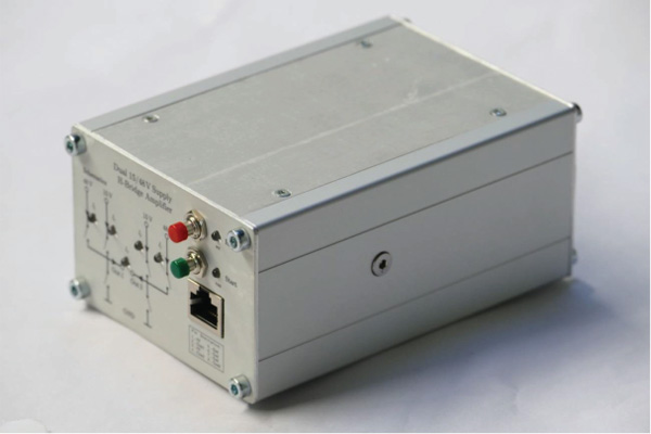
Figure 11 Assembled DSHA in housing.
The first row in Figure 12 is depicting the Boolean input signals used by the logic controller to encode the modes of operation according to Table 1. At t =0μs the input-signals are changing states to COM1..3 = [0,1,1]. This is equivalent with a connection to US2 in forward direction – in other words: boosting has to be started. Consequently MOSFETs M3 and M6 are actuated, which is quite obvious from the second row in Figure 12. The third row depicts the resulting valve voltage uv measured at the output of the DSHA, revealing a voltage step up to US2 characteristic for the boost-period. Finally, the achieved valve current iv is plotted in the fourth row. As planned, the valve current increases during boost-period for tboost = 90 μs up to a maximum of approximately 28 A. Afterwards current is reduced to a target value of roughly 15 A using a reversed voltage US2 (COM1..3 = [0,0,1]). The subsequent raise-period consists of nraise = 10 repeated raise-cycles, each being composed of a forwarded connection to US1 for troanise =7μs (COM1..3 = [1,1,1]) followed by a freewheeling period for troaffise =3μs (COM1..3 = [1,1,0]). Finally raise-period is finished with a reduction of the valve current to approximately 11 A, again using a reversed voltage US2 for timing reasons (COM1..3 = [0,0,1]). The subsequent hold-period resembles the raise-period, except for slightly different timing parameters (see Table 2).
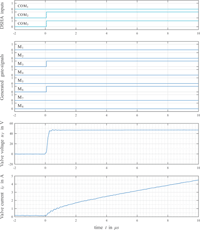
One of the requirements stated in the beginning is a timing accuracy of 1 μ s. This means that the electronics should be capable of changing its state (i.e. its output voltage) within 1 μs, starting from the moment where this change is signalled by the input signals COM. As this is not clearly visible in Figure 12 due to the time scaling, a zoomed version of the measurements is depicted in Figure 13. This plot is clearly showing that a change in the output voltage can be realized within 200 ns.
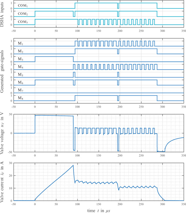
Figure 12 Measurements for a single valve actuation applying a boost-, raise- and holdsequence with the proposed DSHA.
Summed up, the proposed valve current feed (see Figure 5) can be realized using the developed DSHA in a very satisfying way. All requirements are met and given the measurements, there is no sign for any malfunctions or unintended behaviour.
Table 2 Timing Parameters for valve actuation as depicted in Figure 12
| Boost | Raise | Hold | ||
|---|---|---|---|---|
| tboost = 90μs | nraise = 10 | nhold = 9 | ||
| tb,br =4 μs | tr,br = 3 μs | |||
Table 3 Applied values for supply voltages and parameters for the valve
| Supplies | Valve | |||
|---|---|---|---|---|
| US1 = 15 V | RV = 230 mΩ | LV = 150 μH | IV,peak =30 A | |
| US2 = 48 V | Qnom = 0,2 lit/min | Δpnom =5 bar | topen ≈ 320μs | |
Furthermore, Figure 12 is giving a very good visualization of the requirements upon timing precision. After boosting, current is decreased to a targeted raise-level of 15 A within only 4 μs. It is obvious, that even a rather small error of only 1 μs in timing precision will cause a deviation of more than 3 amps in the targeted valve current. In conclusion, it seems that overall dynamics can only be improved at the expanse of tougher timing requirements.
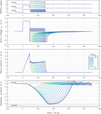
Additional measurements are depicted in Figure 14. Contrary to the single measurement in Figure 12, Figure 14 consists of 21 different measurements, varying the number of repeated raise-cycles nraise within an interval from 0 to 20. Corresponding timing parameters are listed in Table 4. The reason for conducting such measurements is very simple: curiosity about accuracy, sensitivity and timing precision of the developed DSHA. Furthermore, there is a valve position (armature) measurement included in Figure 14, allowing for some assumptions about how the variation in nraise influences the armature movement.
Taking a closer look on the first three rows of Figure 14, showing the DSHA-inputs, the valve voltage uv and the valve current iv, it’s becoming quite clear that the output trajectories (valve voltage and current) are nearly identical. Only the valve current is showing minor deviations, which may be caused by a voltage sag in supplies due to longer valve actuation with increasing value for nraise. Altogether, the DSHA is showing a perfectly reproducible and highly accurate performance.
As far as armature movement is concerned, very similar results are found. Particularly the opening process of the valve within the first 250 to 300 μs is showing a more or less identical shape. There is nearly no deviation recognizable between the different measurements. Furthermore, the distance between single measurements of the armature movement is very evenly spread, implying a strong correlation between the valve stroke and the number of raise-cycles. As far as controllability is concerned, this seems a very promising basement.
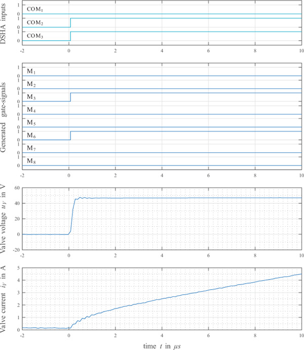
Figure 13 Zoomed view on the response characteristics of the electronics; Output voltage is changing its state within 200 ns.
All together, the measurements in Figures 12 and 14 are confirming, that the development of the DSHA is a step in the right direction, enabling both, high-speed valve actuation as well as precise timing.
Table 4 Timing Parameters for valve actuation as depicted in Figure 14. Boost Raise
| Boost | Raise | |
|---|---|---|
| tboost =90 μs | nraise ∈ [0...20] | |
| tb,br = 4 μs |
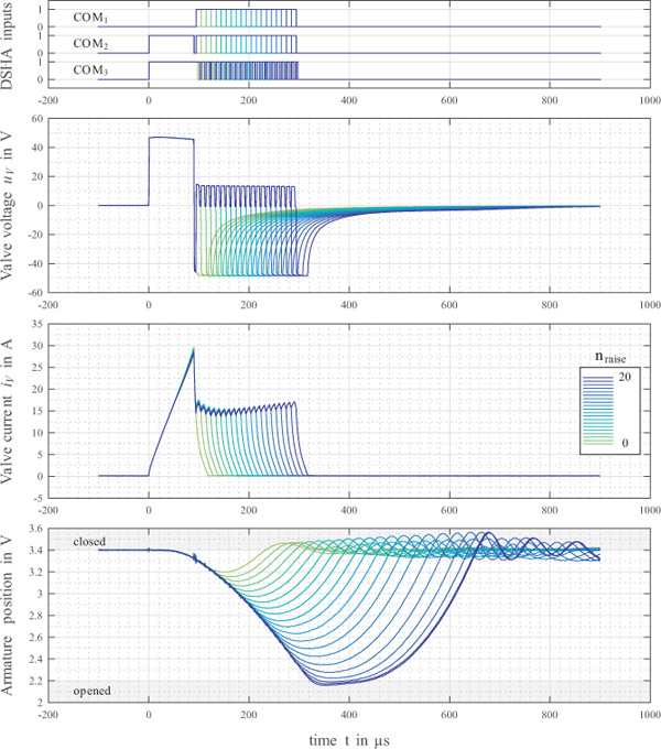
Figure 14 Measurements for several valve actions with varying length, realized by a change in the number of raise-cycles nraise and including armature position measurement.
Another interesting aspect in combination with the measurements in Figure 14 deals with the reproducibility of ballistic pulses. Some literature (Plöckinger et al., 2012) is reporting ballistic pulses to be less reproducible then non-ballistic pulses. As a consequence, ballistic pulses are often neglected for control purposes, resulting in a limitation of system sensitivity as the control variable is being restricted. However, the measurements in Figure 14 are exhibiting a perfectly reproducible behaviour for ballistic pulses. This suggests that for future applications both, power electronics as well as signal generation (PWM etc.), must be given enhanced attention concerning their influence on reproducibility of valve responses.
Summary and Conclusion
This paper is targeting advanced power electronics for high-speed valve actuation. To this end, an actuation sequence derived from common rail injection technology consisting of a boost-, a raise- and a hold-period is implemented. It uses a two voltage level power supply as source driving the solenoid, combining both, fast current rise while boosting with the high voltage and low current ripple in the raise- and hold-period where low voltage is used. Furthermore, due to the absence of a boost-capacitor, recharge-periods can be omitted completely. Destructive activation of the electronic switches is avoided by an integrated logic controller. It realizes a state-machine allowing for appropriate modes of operation and high timing precision. Measurements with prototype electronics and a fast valve as load proved a proper operation of the power electronics according to the intended performance characteristics in terms of precise and very repeatable valve responses.
The main conclusion is that it pays to spend more research and development effort on power electronics in order to fully utilize the performance potential of fast switching valve solenoids. Precise timing of the signals generated by this electronics is an essential feature to achieve a high solenoid performance.
Nomenclature
| HS | High Side |
| LS | Low Side |
| SV | Valve armature position |
| iV | Valve solenoid current |
| LV | Valve solenoid inductivity |
| uV | Valve solenoid voltage |
| iboost | Maximum boost current |
| iraise | Average raise current |
| ihold | Average hold current |
| tboost | Boost time |
| tb,br | Break time after boost-period |
| On-time during raise-cycle | |
| Off-time during raise-cycle | |
| tr,br | Break time after raise-period |
| On-time during hold-cycle | |
| Off-time during hold-cycle | |
| nraise | Number of repeated raise-cycles |
| nhold | Number of repeated hold-cycles |
| M1 to M8 | MOSFETs and corresponding gate signals used in the proposed H-bridge design |
| US1 and US2 | Different voltage levels acting as supply |
| COM1 to COM3 | Boolean input signals for the logic controller |
References
Balogh, L., 2017. Fundamentals of MOSFET and IGBT Gate Driver Circuits. Texas Instruments Application Report SLUA618, edition 2017–03. Available from: http://www.ti.com/lit/ml/slua618/slua618.pdf [Accessed 19 October 2018]
Bosch Rexroth, 2012. Booster amplifier, Type VT-MSFA1. Bosch Rexroth datasheet RE 30260, edition 2012–04. Available from: https://md.boschrexroth.com/modules/BRMV2PDFDownload-internet.dll/re302602012-04.pdf?db=brmv2&lvid=1163141&mvid=13560&clid=1&sid=8C40797B486BD4C988A4C3DB40B8B87B.borex-tc&sch=M&id=13560,1,1163141 [Accessed 13 September 2018]
Brown, F. T., Tentarelli, S. C. and Ramachandran, S., 1988. A hydraulic rotary switched-inertance servo-transformer. Journal of Dynamic Systems, Measurement, and Control, 110 (2), 144–150.
Ehsan, Md., Rampen, W. H. S. and Salter, S. H., 1997. Modeling of digital-displacement pump-motors and their application as hydraulic drives for nonuniform loads. Journal of Dynamic Systems, Measurement, and Control, 122 (1), 210–215.
International Rectifier, 2007. HV Floating MOS-Gate Driver ICs. International Rectifier Application Note AN-978, edition 2007–03. Available from: https://www.infineon.com/dgdl/Infineon-HVFloating MOS Gate Drivers AN978-AN-v01 00- EN.pdf?fileId=5546d462533600a40153559f 7cf21200 [Accessed 19 October 2018].
Kallenbach, E., Eick, R., Quendt, P., Ströhla, T., Feindt, K. and Kallenbach, M., 2003. Elektromagnete. 2nd edition. Wiesbaden: Teubner Verlag.
Laamanen, A., Linjama, M. and Vilenius, M., 2007. On the pressure peak minimization in digital hydraulics. Proceedings of the Tenth Scandinavian International Conference on Fluid Power, 21–23 May, Tampere, Finland. 107-121.
Li, P. X., Su, M. and Zhang, D. B., 2017. Response characteristic of highspeed on/off valve with double voltage driving circuit. IOP Conference Series: Materials Science and Engineering, 220(1).
Linjama, M., 2011. Digital Fluid Power – State of the Art. Proceedings of the Twelfth Scandinavian International Conference on Fluid Power, 18–20 May 2011, Tampere, Finland. 331–354.
Linjama, M., Paloniitty, M., Tiainen, L. and Huhtala K., 2015. Mechatronic design of digital hydraulic micro valve package. The Second International Conference on Dynamics and Vibroacoustics of Machines, 15–17 September 2014, Samara, Russia. 610–617.
Messner, F., Scheidl, R., 2016. Development and experimental results of a small fast switching valve derived from fuel injection technology. Proceedings of the Eighth Workshop on Digital Fluid Power, 24–25 May 2016, Tampere, Finland. 9–25.
Nørgård, C., Bech, M. M., Roemer, D. B. and Pedersen, H. C., 2016. Optimization of Moving CoilActuators for Digital Displacement Machines. Proceedings of the Eighth Workshop on Digital Fluid Power, 24–25 May 2016, Tampere, Finland. 39–54.
Pan, M., Plummer, A. and El Agha, A., 2017. Theoretical and Experimental Studies of a Switched Inertance Hydraulic System in a Four-Port High-Speed Switching Valve Configuration. Energies, 10(6), 780.
Panguloori, R., 2017. Achieve Bidirectional Control and Protection Through Back-to-Back Connected eFuse Devices. Texas Instruments Application Report SLVA948, 2017–12.Available from:http://www.ti.com/lit/an/slva94_8/slva948.pdf [Accessed 16 September 2018]
Plöckinger, A., Huova, M. and Scheidl, R., 2012. Simulation and experimental results of PWM control for digital hydraulics. Proceedings of the Fifth Workshop on Digital Fluid Power, 24–25 October 2012, Tampere, Finland. 133–151.
Reif, K., 2011. Bosch Grundlagen Fahrzeug- und Motorentechnik. Bosch Fachinformation Automobil. Vieweg + Teubner.
Reif, K., 2015. Ottomotor – Management im Überblick. Bosch Fachinformation Automobil. Springer Vieweg.
Robert Bosch GmbH, 2010. Verfahren zum Betreiben einer Brennkraftmaschine, bei dem ein Magnetventil zum Einspritzen von Kraftstoff betätigt wird. German patent application DE102010027989A1. 2010-04-20.
Robert Bosch GmbH, 2016. Verfahren zur Ansteuerung eines Magnetventils eines Kraftstoffinjektors. German patent application DE102016203196A1. 2016–0229.
Roemer, D. B., Johansen, P., Bech, M. M. and Pedersen, H. C., 2014. Simulation and Experimental Testing of an Actuator for a Fast Switching On-Off Valve Suitable to Efficient Displacement Machines. Proceedings of the Ninth JFPS International Symposium on Fluid Power. 28-31 October 2014, Matsue, Japan. 468–474.
Scheidl, R., Schindler, D., Riha, G. and Leitner, W., 1995. Basics for the energy-efficient control of hydraulic drives by switching techniques. Proceedings of the Third Conference on Mechatronics and Robotics. 118–131. Wiesbaden: Vieweg+Teubner Verlag.
Specovius, J., 2015. Grundkurs Leistungselektronik. 7th edition. Wiesbaden: Springer Vieweg Verlag.
Uusitalo, J. P., Lauttamus, T., Linjama, M., Söderlund, L., Vilenius, M., Kettunen, L.,2007. Miniaturized bistable seat valve. The Tenth Scandinavian International Conference on Fluid Power, 21–23 May 2007, Tampere, Finland. 379–391.
Biographies

Florian Messner studied mechatronics at the Johannes Kepler University Linz and received his MSc in 2013. Since 2013 he is employed at the Institute of Machine Design and Hydraulic Drives as Scientific Assistant and working on his PhD. His main research topic is the development of high-speed switching valves.

Rudolf Scheidl received his MSc of Mechanical Engineering and his Doctorate of Engineering Sciences at the Vienna University of Technology. He gained industrial research and development experience in agricultural machinery, continuous casting technology and paper mills. Since Dec. 1990 he is a full Professor for Mechanical Engineering at the Johannes Kepler University Linz. Research topics: hydraulic drive technology and mechatronic design.
International Journal of Fluid Power, Vol. 20 1, 125–150.
doi: 10.13052/ijfp1439-9776.2015
© 2019 River Publishers