Research on Influence of Different Types of Orifice on Axial Steady-state Flow Force in Cartridge Proportional Valve
Haibo Xie1, Li Tan1,*, Jianbin Liu2, Hanben Chen1 and Huayong Yang1
1 State Key Laboratory of Fluid Power and Mechatronic Systems, Zhejiang University, Hangzhou, 310027, Zhejiang, China
2 Key Laboratory of Mechanism Theory and Equipment Design, Ministry of Education, Tianjin University, Tianjin, 300072, China
E-mail: ltan@zju.edu.cn
* Corresponding Author
Received 04 Feburary 2019; Accepted 31 July 2019;
Publication 26 August 2019
Abstract
This article mainly investigates how orifice structure influences the characteristics of steady-state flow force. The research model of this paper is originated from a cartridge proportional valve. Firstly, predicting characteristics of the flow force working on poppet in different types of orifice through CFD simulations; secondly, several parameters of poppet and seat, which may affect the characteristics of flow force, are defined, a series of CFD calculations were conducted to find a rule how each parameter influences flow force; thirdly, according to the analysis, optimization of orifice structure parameters has been successfully realized. Finally, a test bench was established to validate the simulation results.
The results show that the orifice type has a significant influence on flow force, which indicates that choosing certain type of orifice can effectively decrease the influence of flow force, and the negative effect of flow force can be reduced within an acceptable extent. Besides, the influence of orifice on pressure difference has been also taken into account. The experimental results agree well with the simulative one.
Keywords: Flow force, cartridge valves, CFD simulation, design optimization.
1 Introduction
The flow force is one of the main factors that influence the performance of a valve. Thus, studies on its characteristics and method of reducing the negative effect of flow force are always a poplar topic.Alot of researchers have made much contributions. In USA, as early as 1950s, Lee and Blackburn [1], Stone [2] had investigated the steady-state flow forces in poppet valves. And in China, Cao et al. [3, 4] studied flow force and pressure distribution of the main poppet in a converged flow poppet valve in both theoretical and experimental ways, besides, Shi et al. [5] presented a new technique to reduce the flow force in a poppet valve, and Tang et al. [6] proposed a moving seat method, which changed the moving relationship between conical poppet and valve seat, to reduce flow force. With the development of computer technology, computational fluid dynamics (CFD) software has brought much convenience for flow investigation and widely applied in many fields. In recent years, researchers interested in hydraulics have done much investigations on various valves, such as poppet valve, conical valve and so on, through CFD software. Zhang et al. [7] adopted two-phase model to investigate the steady-state flow force in a sliding valve whose flow direction is converged, Ye et al. [8] studied how different notches affect the characteristics of flow force in a spool valve, Bordovsky and Murrenhoff [9] tried to find out how different geometries and oil temperatures affect steady-state flow forces in spool valves with the help of CFD simulations. Furthermore, Finesso and Rundo [10] conducted a research on a conical poppet relief valve through both CFD simulations and experiments, Rundo and Altare [11] compared the analytical and numerical methods for evaluating the flow force in a conical poppet valve and Liu et al. [12] designed a structure which is called damping tail that can effectively regulate the flow force in a counterbalance valve, and found its optimal size through CFD simulation.
In modern hydraulics, cartridge valves become more and more important and are now commonly applied in many hydraulic fields for its large flow rate capacity, excellent leak-proofness and so on. Several scholars and researchers had done some work that are relevant to cartridge valves, Masao and Shigeru [13] used theoretical method to study the flow force in a two-way cartridge valve, Zheng and Quan [14] found that truncated poppet has a stronger flux capacity than the usual one, and Jalil et al. [15] used CFD simulation and PIV technique to investigate the fluid flow of truncated conical poppet valve. Moreover, Zardin et al. [16] designed a new two-stage on/off cartridge valve.
This paper mainly discusses that how orifice structure influences the characteristics on flow force in a cartridge proportional valve. Firstly, comparing the characteristics of flow force of three types of orifices under the same parameters, and selecting a certain type of orifice as the optimization subject; secondly, exploring a rule how each parameter influences the characteristics of flow force through a series of CFD calculations, and then, according to the analysis, optimizing the orifice structure; at last, a test bench was established in order to validate the results of CFD calculation.
Nomenclature
| Q | flow rate |
| FF | flow force |
| k | kinetic energy of the turbulence |
| Gb,Gy,YM | energy components of k-ɛ equation |
| C1ɛ,C2ɛ,C3ɛ | constants of the k –ɛ model |
| ρ | fluid density |
| Pi ,Po | inlet pressure and outlet pressure |
| din | diameter of inlet channel |
| FM | force measured in test |
| θ | angle of the chamfer of poppet |
| D | diameter of conical poppet |
| Lp1 | axial length of the chamfer on poppet |
| Lp2 | radial length of the chamfer on poppet |
| Ls1 | axial length of the chamfer on seat |
| Ls2 | radial length of the chamfer on seat |
| x | poppet position |
| F | total force working on poppet |
| ɛ | dissipation factor |
| Sk,Sɛ | user-defined source term |
| μt | turbulent viscosity |
| ςk,ςɛ | turbulent Prandtl numbers |
| ΔP | Pi – Po |
| dout | diameter of outlet channel |
| Ai ,Ao | sectional area of poppet |
| α | angle of the chamfer on seat |
2 Cartridge Proportional Valve and Orifice Types
2.1 Description of a Cartridge Proportional Valve
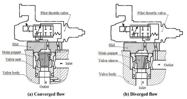
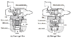
According to flow direction, poppet valves can be classified into two types: converged flow and diverged flow. Obviously, characteristics of flow force in two valves will be definitely different. Figure 1 shows two different types of cartridge valves, which are the base model of research in this paper.
2.2 Different Types of Orifice in Poppet Valve
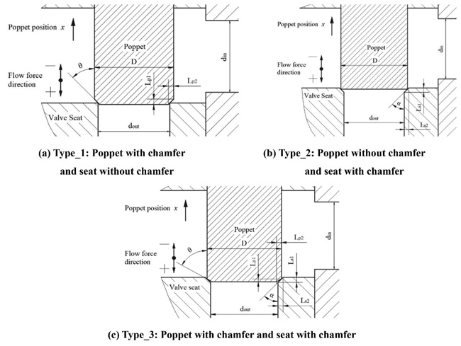
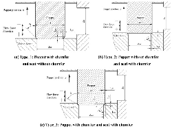
Three different types of orifices and their corresponding parameters are shown in Figure 2, besides, the direction of flow force and poppet position are also represented in the picture. The diameter of inlet din, outlet dout and poppet D are equivalent in all three situations.
Figure 2(a) shows the type_1, in this structure, a chamfer is machined on the main poppet.
Figure 2(b) shows the type_2, compared to the type_1, the chamfer is machined on the valve seat.
Figure 2(c) shows the type 3 that both the poppet and the seat have a chamfer.
Figure 1 Two cartridge valves which are used for research.
Figure 2 Three different seat geometries.
3 3D Model and Simulation Set Up
3.1 3D Model
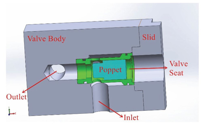
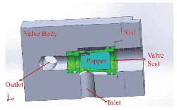
3D model of the valve, which was created in SolidWorks, is represented in Figure 3, the valve is comprised of a valve body, a valve seat, a poppet and a slid. Channel of inlet and outlet, whose diameter are 16 mm, were drilled on the valve body.
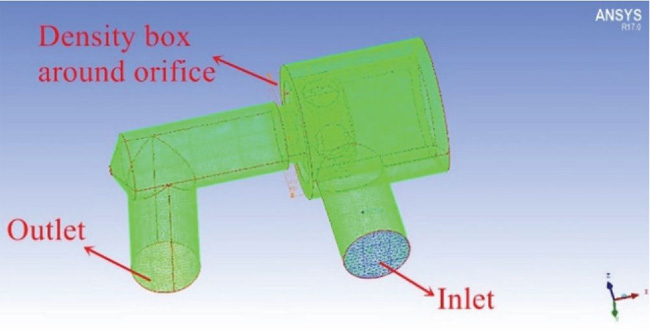
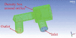
Mesh models of fluid in the valve were generated in ICEM CFD, and the type of them is chosen as tetrahedral which possesses an excellent adaptation. In order to obtain an accurate and reliable result, mesh refinement had been done. First, a general refinement was realized by increasing the number of cells in whole fluid domain; second, a local refinement was realized through setting a density box around the orifice, because it is in this area where the high velocity and pressure gradients occur, which leads to a much more complicated flow state. Furthermore, the quality of mesh had also been taken into account, and several steps, including refinement of line and surface of the poppet, had been done to improve it. Fluid mesh model generated in ICEM CFD has been represented in Figure 4.
Figure 3 3D model of valve.
Figure 4 Mesh model generated in ICEM CFD.
3.2 Model Setup
3.2.1 Model description
Undoubtedly, the simulation model should be chosen as turbulence model. Fluent have provided three common turbulence models for users, they are k –ɛ model, k –ω model and Reynolds stress model and the k-ɛ model is the most widely used one in hydraulic valve researches. According to it, the turbulence kinetic energy k and dissipation ɛ rate are derived from the transport functions below:
| (1) |
| (2) |
Meaning of parameters are as follows: Gk refers to the generation of turbulence kinetic energy caused by the mean velocity gradients, Gb represents the generation of turbulence kinetic energy resulted from buoyancy, and YM is the contribution of the fluctuating dilatation in compressible turbulence to the overall dissipation rate, besides, C1ɛ , C2ɛ and C3ɛ represent model constants, ςk and ςɛ refer to the turbulent Prandtl numbers for k and ɛ, Sk and Sɛ represent user-defined source terms.
The turbulent viscosity μt can be calculated through the equation:
| (3) |
in above equation, Cμ represents the model constant.
Default values of model constants have already been represented in Fluent: C1ɛ = 1.44, C2ɛ = 1.92, C3ɛ = 0.09, ςk = 1.0, ςɛ = 1.3.
3.2.2 Description of simulation settings and process for simulation
Obviously, flow state in the valve should be regarded as incompressible. In Fluent, the inlet type was set as velocity-inlet, and the outlet was defined as pressure-outlet, besides, the value of outlet pressure is always 0.1 MPa.
Three poppet positions had been picked from the operating stroke 0~3 mm, and eight flow rate values were selected from 0~150 L/Min, consequently, characteristics of flow force under various conditions can be clearly represented, the relationship between flow rate and poppet position is reported in Table 1.
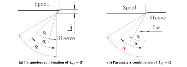
Table 2 represents the parameters of the type_2, which will be used in simulation. Since after changing the value of angle α, geometry of the poppet whose length parameter is the parameter Ls1 is quite different with the one whose length parameter is Ls2 , which is shown in Figure 5 (in this paper, we define that Lsi – α (i = 1 or 2) represents parameter combination of Lsi and α). Therefore, it is necessary to divide the simulation into two parts: the parameter combination Ls1 – α and Ls2 – α. The process of obtaining the flow force in certain condition is as follows: first, determine poppet position x, for instance, setting x = 3 mm; second, determine the flow direction, for instance, converged flow; finally, choose the parameters combination, for example, Ls1 – α, and then assigning the corresponding value for Ls1 and α, such as Ls1 = 1.2 mm, α = 30°, thus, flow force acting on poppet when x = 3 mm, Ls1 = 1.2 mm, α = 30° can be obtained. In this way, flow force in different parameters combinations and operation strokes can be obtained by CFD simulation.
Table 1 Relationship between flow rate and poppet position
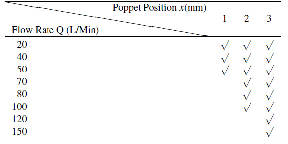
Table 2 Parameters of type_2
| Type of Orifice | Flow Direction | Axial Length of ChamferLs1 (mm) | Radial Length of Angle of Chamfer | ChamferLs2 (mm) «(°) |
| Poppet without | Converged flow | 0.8 | 0.8 | 45 |
| chamfer and | Diverged flow | 1 | 1 | 60 |
| seat with chamfer | 1.2 | 1.2 | 70 |
Figure 5 Comparison of two different types of parameters combination.
The computer used for simulation is equipped with a CPU that contains 16-core (32 threads) and 30 of them were assigned for the parallel calculation. The computational time to simulate a single point is relevant to many factors, such as the number of mesh cells, flow rate and poppet position. For example, in condition that x = 3 mm, Q = 150L/Min and 1.3 million cells, it takes nearly 15 minutes to complete the calculation, while in condition that x = 3 mm, Q = 150 L/Min, 0.65 million cells, time of completion is about 9 minutes.
4 Analysis of CFD Simulations
The contents mainly discussed in this section are as follows: firstly, it analyzes and compares the general characteristics of three orifices under the same parameters combination; secondly, choosing the optimal orifice, whose characteristics of flow force is better than the other two, as the main research object, and then exploring the rules how each parameter influences characteristics of flow force and pressure difference; thirdly, according to the analysis, obtaining the optimal parameters of orifice, which decreases the influence of flow force to the minimum extent; finally, validation of mesh independence was conducted to prove the accuracy of results.
4.1 Theoretical Calculation Method for Flow Force
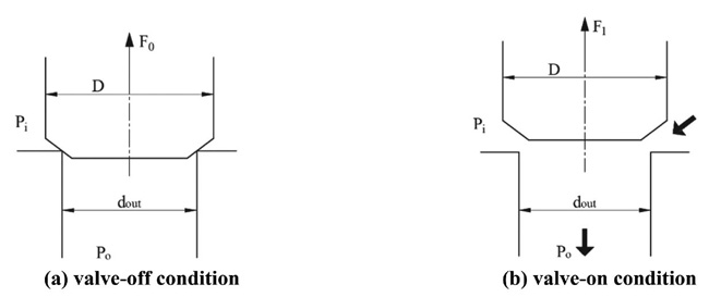
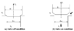
Fluent can only report the total force (result of CFD calculation is about the resultant force acting on one area) of a certain surface as opposed to the flow force, therefore, a theoretical formula, which can reveal the relationship between the total force obtained from Fluent and the flow force, should be established. Figure 6 shows a valve whose inlet pressure Pi and outlet pressure Po are constants, and then, the flow force working upon poppet can be calculated through the following formula:
Figure 6 Two different work conditions of the valve.
In above equation, F0 refers to the total force exerting on poppet in valve-off situation while F1 is the total force in valve-on condition, Pi and Po refer to the inlet pressure and the outlet pressure, and represent the area where inlet pressure and outlet pressure acts.
Besides, according to the direction of flow force shown in the Figure 2, the positive flow force tends to close the orifice of the valve, and conversely, the negative flow force tends to open the orifice.
4.2 Characteristics of Three Types of Orifice
4.2.1 Characteristics of type_1
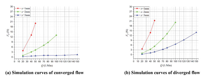
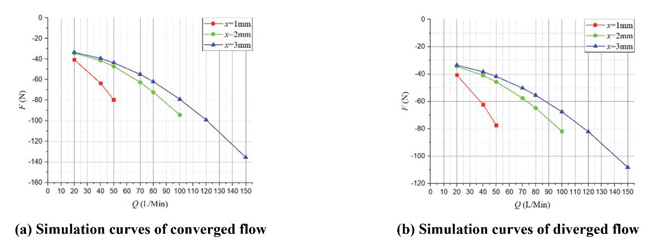
Figure 7 shows the FF – Q simulation curves of both converged and diverged flow in different poppet positions when Lp2 = 1 mm, θ = 45° and Figure 8 represents the corresponding total force that acts on main poppet.
Figure 7 Simulation curves of FF – Q in different poppet positions when Lp2 = 1 mm, θ = 45°.
Figure 8 Simulation curves of F – Q in different poppet positions when Lp2 = 1 mm, θ = 45°.
In converged situation, with the increasing of poppet position and flow rate, magnitude of flow force increases and the direction gradually turns to negative from positive, which put the valve in an unstable state. For instance, in x = 1 mm, Q = 50 L/Min, flow force is in positive direction and only about 2 N which is so small that can be neglected, while in x = 3 mm, Q = 150 L/Min, flow force turns to negative direction and reaches –21 N which takes 13% of the total force.
In diverged situation, different from the converged one, direction of flow force in all poppet positions is positive, which helps improve the stability of the valve, however, the magnitude of flow force keeps in very high level in whole operation range. When x = 1 mm, Q = 50 L/Min, flow force can rise to 19 N that occupies 24% of the total force, in x = 2 mm, Q = 100 L/Min, flow force reaches 21 N which is 27% of the total force working upon poppet, and in x = 3 mm, Q = 150 L/Min, flow force can account for 15%. Without doubt, in this situation, flow force will definitely bring a huge disturbance on poppet adjustment in whole operating stroke.
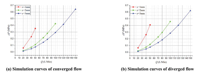
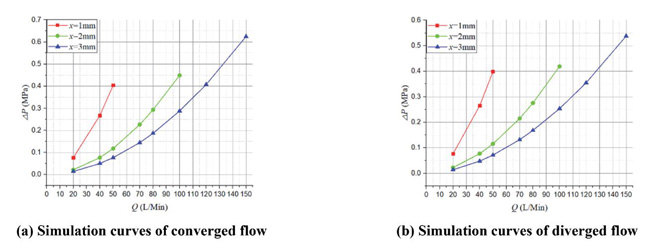
Figure 9 shows the corresponding ΔP – Q simulation curves. As we can see, there is no obvious difference between converged and diverged direction.
4.2.2 Characteristics of type_2
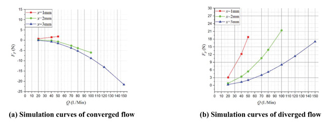
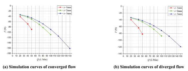
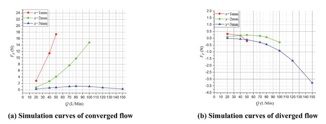
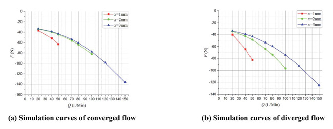
Figure 10 shows the FF – Q simulation curves of both converged and diverged flow in different poppet positions when Ls2 = 1 mm, α = 45° and Figure 11 shows the corresponding total force.
In converged situation, although direction of flow force is positive in whole operation range, flow force decreases with the increase of poppet position, for example, in x = 1 mm, Q = 50 L/Min, flow force can be as high as 17 N that accounts for 27% of force acting on poppet, and in x = 2 mm, Q = 100 L/Min, flow force reaches 15 N which is 19% of the total force, however, when poppet position reaches 3 mm, the FF curve is around the zero line, which means flow force in such condition is so small that can be neglected.
Figure 9 Simulation curves of ΔP – Q in different poppet positions when Lp2 = 1 mm, θ = 45°.
Figure 10 Simulation curves of FF – Q in different poppet positions when Ls2 = 1 mm, α = 45°.
Figure 11 Simulation curves of F – Q in different poppet positions when Ls2 = 1 mm, α = 45°.
In diverged situation, magnitude of flow force in whole operating stroke is so small that can be neglected, for example, the maximum of flow force is just –3.25 N, which occurs at poppet position x = 3 mm and flow rate Q = 150 L/Min, and it is only 2% of the total force.
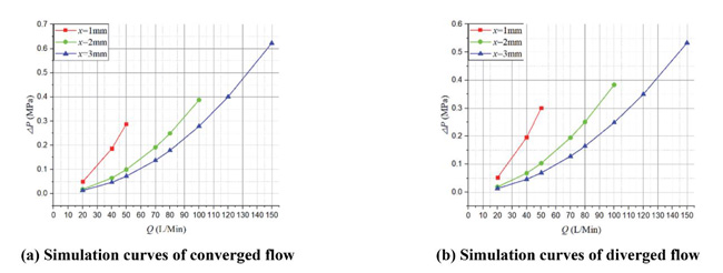
Figure 12 shows the corresponding ΔP – Q simulation curves. There is no much difference between converged and diverged situation except in x = 3 mm where the pressure of diverged direction is 0.1 MPa lower than the one of converged situation. Besides, in general, pressure drop of type_2 is lower than type_1, especially in diverged situation.
4.2.3 Characteristics of type 3
Figure 13 shows the FF – Q simulation curves of both converged and diverged direction in different poppet positions when Ls2 = 1 mm, α = 45°, Lp2 = 1 mm and θ = 45°, and Figure 14 shows the corresponding total force.
Figure 12 Simulation curves of ΔP – Q in different poppet positions when Ls2 = 1 mm, α = 45°.
Figure 13 Simulation curves of FF – Q in different poppet positions when Ls2 = 1 mm, α = 45°, Lp2 = 1 mm and θ = 45°.
Figure 14 Simulation curves of F – Q in different poppet positions when Ls2 = 1 mm, α = 45°, Lp2 = 1 mm and θ = 45°.
In converged situation, similar to type_2, flow force keeps in positive direction in whole operation stroke, and its magnitude reaches a relatively high value. In x = 1 mm, Q = 50 L/Min, flow force can rise to 20.5 N that accounts for 26% of the total force, which will undoubtedly bring a huge negative influence on valve performance, and in x = 2 mm, Q = 100 L/Min, although flow force only reach 12.5 N compared to type_2, it still takes 13% of the total force.
In diverged situation, similar to type_1, although flow force is in positive direction, which helps to reinforce the stability of valve, the magnitude of flow force keeps in a high level in whole operating range. In x = 1 mm, Q = 50 L/Min, flow force can be as high as 21.5 N which takes 27% of the total force, and in x = 2 mm, Q = 100 L/Min, flow force reaches 20 N which occupies 24% of the total force, obviously, in these situations, flow force will undoubtedly bring a huge negative influence on valve performance, however, when poppet position reaches x = 3 mm, magnitude of flow force goes down to a relatively small value, for example, in Q = 150 L/Min, flow force is just about 9 N which only accounts for 8% of force acting on poppet.
Figure 15 shows the corresponding ΔP – Q simulation curves. There is no obvious difference between two types of flow direction. Compared to the former two, the magnitude of pressure drop of type 3 is a little lower than type_1 while a bit higher than type_2.
4.3 Effects of Parameters on Flow Force and Pressure Drop
In this section, several critical parameters have been introduced to the orifice in order to further investigate how the geometry of orifice affects the flow force and pressure difference, and by conducting a series of simulation, the effect rule of each parameter can be concluded, as a result, the optimal parameters combination of orifice can be obtained.
According to the analysis in Section 4.2, it is easy to see that compared to the other two orifices, type_2 is the optimal type for its small flow force in diverged flow situation and low pressure drop in both two flow directions. Therefore, in this section, type_2 is chosen as the research object.
Figure 15 Simulation curves of ΔP – Q in different poppet positions when Ls2= 1 mm, α = 45°, Lp2 = 1 mm and θ = 45°.
4.3.1 Effects of α when Ls1 is a constant
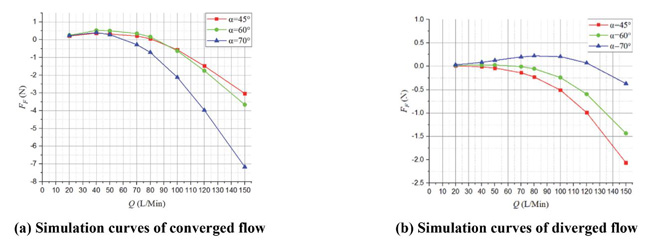
Figure 16 represents the FF – Q simulation curves of both converged and diverged flow when α is variable, and x = 3 mm, Ls1 = 0.8 mm. In converged situation, flow force becomes large with the increase of angle α, however, in diverged situation, the trend is totally inverse. Moreover, flow force of both two flow directions are relatively small, especially the diverged one whose maximum flow force is just about –2N.
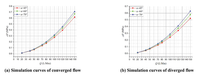
Figure 17 represents the corresponding ΔP – Q simulation curves. Pressure drop ΔP is proportional to angle α, and the maximum value of variation has been over 0.1 MPa.
Apparently, selecting a small value for angle α helps to obtain a small flow force in converged situation and a low pressure difference in both two situations.
Figure 16 Simulation curves of FF – Q when α is variable, and x = 3 mm, Ls1 = 0.8 mm.
Figure 17 Simulation curves of ΔP – Q when α is variable, and x = 3 mm, Ls1= 0.8 mm.
4.3.2 Effects of Ls1 when α is a constant
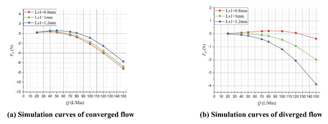
Figure 18 represents the FF – Q simulation curves of both converged and diverged flow when Ls1 is variable, and x = 3 mm, α = 70°. With the increase of Ls1, flow force of both converged and diverged flow changes in a small range.
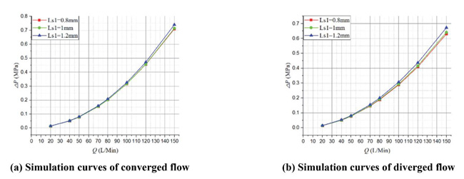
Figure 19 represents corresponding ΔP – Q simulation curves. With the increase of α, ΔP almost has no change, which means pressure drop is also insensitive to α.
Obviously, when angle α is constant, both the flow force and pressure drop are not affected by the variation of Ls1.
4.3.3 Effects of α when Ls2 is a constant
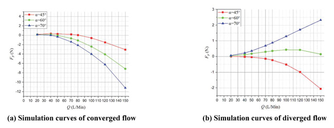
Figure 20 represents the FF – Q simulation curves of both converged and diverged flow when α is variable, and x = 3 mm Ls2 = 0.8 mm. In converged situation, flow force is directly proportional to the angle α, and the increment is relatively large, for example, in Q = 150 L/Min, the flow force of α = 70° reaches –11 N which is 3.7 times more than the one of α = 45°. However, in diverged situation, flow force only varies around the zero line which means, in this situation, disturbance from flow force can be neglected even if the direction of flow force is negative.
Figure 18 Simulation curves of FF – Q when Ls1 is variable, and x = 3 mm, α =70°.
Figure 19 Simulation curves of ΔP – Q when Ls1 is variable, and x = 3 mm, α = 70°.
Figure 20 Simulation curves of FF – Q when α is variable, and x = 3 mm, Ls2 = 0.8 mm.
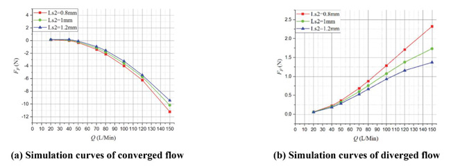
Figure 21 Simulation curves of FF – Q when Ls2 is variable, and x = 3 mm, α =70°.
According to the variation law of pressure drop in the Sections 4.3.1 and 4.3.2, pressure drop in this situation is definitely similar to that in 4.3.1.
4.3.4 Effects of Ls2 when α is a constant
Figure 21 represents the FF – Q simulation curves of both converged and diverged flow when Ls2 is variable, and x = 3 mm, α = 70°. With the increase of Ls2 , flow force of both converged and diverged flow decline, and the decrement is so small that can be neglected.
Likewise, the pressure drop is definitely similar to that in 4.3.2.
4.4 Optimal Parameters Combination of Type 2
According to the conclusions which are found in Section 4.3, the optimal parameters combination can be obtained. In this section, the optimal parameters combination of type_2 and its general characteristics will be represented and analyzed.
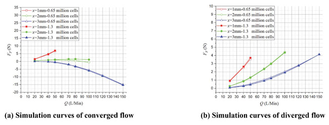
Figure 22 Mesh independence verification: FF – Q curves when Ls2 = 0.8 mm, α = 80°.
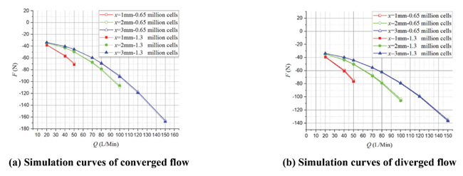
Figure 23 Mesh independence verification: F – Q curves when Ls2 = 0.8 mm, α = 80°.
Figure 22 represents the simulation curves of FF – Q of both converged and diverged flow direction when Ls2 = 0.8 mm, α =80°, Figure 23 shows the corresponding total force acting on poppet.
In converged situation, flow force in small and medium poppet position are largely decreased. In x = 1 mm, Q = 50 L/Min, flow force is only about 6 N which is 8% of the total force, in x = 2 mm, curve of flow force is around the zero line, and but in large poppet position, such as x = 3 mm, flow force increases, for example, in Q = 150 L/Min, it increases to –15 N however, the total force acting on poppet is also relatively high(nearly –170 N), thus, the proportion of flow force will not rise too high, in this time, flow force accounts for 9%.
In diverged situation, direction of flow force keeps positive in whole operating stroke, and the maximum flow force is so small that can be neglected, for instance, in x = 1 mm, Q = 50 L/Min, flow force is just about 3.5 N which only accounts for 4.5% of the total force working poppet, and in x = 2 mm, Q = 100 L/Min, flow force is just about 4.4 N which only occupied 4% of the total force, and in x = 3 mm, Q = 150 L/Min, flow force is just about 4.2 N which only takes 3% of the total force.
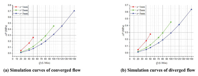
Figure 24 Simulation curves of ΔP – Q when Ls2 = 0.8 mm, α = 80°.
Figure 24 represents the corresponding ΔP – Q simulation curves. According to the analysis in Sections 4.31 and 4.33, with the increase of angle α, pressure drop of both converged and diverged flow will go up, however, the magnitude of variation is acceptable, for example, the maximum increment is only about 0.1 MPa when x = 3 mm, Q = 150 L/Min.
Besides, since the fluid model is comprised of mesh cells, results of calculation will be undoubtedly affected by the number of mesh cells. In order to prove the accuracy of results in this paper, validation of mesh independence had been done. Simulation results, which were obtained in 0.65 million cells and 1.3 million cells, are represented to demonstrate the reliability of calculation.
Figure 21 shows the FF – Q curves when Ls2 = 0.8 mm, α = 80°, and the corresponding F – Q curves are represented in Figure 22.
As we can see from them, results of 0.65 million cells and 1.3 million cells are extremely close, therefore, the results of 0.65 million cells adopted in this paper are accurate and reliable enough.
5 Test Bench and Experimental Validation
5.1 Test Bench
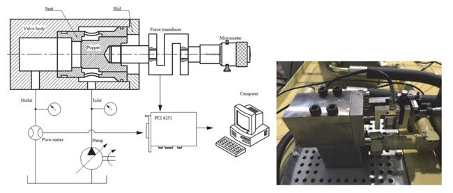
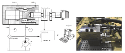
In order to validate the results of simulations in above sections, a test bench was set up to measure the total force exerting on the poppet. Figure 25 shows the test bench.
The test bench is composed of a valve body, a valve seat, a slid, a force transducer with a range of 0~500 N, a specific poppet, a micrometer, a Hydrotechnik flow meter, two pressure gauges(range 0~4 Mpa), a pump, a DAQ card(data acquisition card), and a computer which is used to report the real-time data obtained by force transducer(range 0~500 N, accuracy 0.03%) and turbine flow meter. Moreover, a threaded hole tapped on the back surface of the tested poppet is used to connect with force transducer.
Figure 25 Test bench.
5.2 Experimental Validation
During the experiment, first, move poppet to the expected position and then turn the lock function on; second, turn on the variable pump and adjust flow rate to the expected value. The inlet pressure and outlet pressure can be observed by the pressure gauge. The total force working on the poppet can be acquired by the force transducer.
Bringing the pressure of inlet and outlet, and the measured force reported in the computer into the formula which proposed in Section 4.1, the flow force under certain poppet position and flow rate can be obtained.
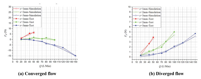
Experimental results of the optimal orifice are shown in Figure 26, it is clear that results of test show good agreement with results of simulation.
Figure 26 Experimental results of the optimal orifice.
6 Conclusions
This paper mainly investigates the influences of three different orifices exerted on characteristics of flow force. First, comparing the characteristics of flow force of three types of orifices under the same parameters, and choose a certain type as the optimization subject; second, introducing several parameters that may affect the characteristics of flow force and exploring the rule that how each parameter influences the flow force through a series of CFD calculations, then, according to the analysis, optimizing the orifice structure; at last, a test bench was established in order to validate the results of CFD calculation.
The main conclusions are as follows:
- For the orifice type_1. In converged flow situation, flow force in small and medium poppet positions, such as x = 1 mm, x = 2 mm, are so small that can be neglected, however, flow force becomes large when comes to the large poppet position and flow rate. In diverged flow, different from the converged situation, in whole operating stroke, direction of flow force keeps positive, and magnitude of flow force is extremely large, which indicates that poppet will consistently suffer from the disturbance of flow force;
- For the orifice type_2. In converged situation, contrary to type_1, direction of flow force keeps positive in whole operating stroke, and magnitude of flow force decreases as the poppet position increases, flow force can reach an extremely high value in small or medium poppet position, however, it descends to zero when poppet reaches its maximum range (x = 3 mm). In diverged flow, in whole operating range, magnitude of flow force is so small that can be neglected even though the direction of flow force is negative;
- For the orifice type_3. In converged situation, similar to type_2, value of flow force goes down with the increase of poppet position, in small and medium poppet positions, flow force can take a large percentage of total force acting on poppet, which will undoubtedly bring a disturbance on control of the poppet, however, magnitude of flow force decreases to nearly zero when poppet position further enlarges. In diverged flow, similar to type_1, magnitude of flow force keeps in a high level in whole operating range. Moreover, direction of flow force of both converged and diverged flow are positive;
- Flow force of both converged and diverged flow are sensitive to the variation of angle of the chamfer, which provides a guidance to optimize the characteristic of flow force;
- Flow force of both converged and diverged flow can be reduced to a relatively low level after optimization.
In addition, pressure drop of each orifice is also represented in this paper, it is clear to see that pressure drop changes little with variation of parameters, the maximum variation is nearly 0.1 MPa, and there is little difference among three types of orifice. Results of CFD calculation and experiment show good agreement, which indicates that CFD simulation results are reliable enough. And we believe the investigation can provide further guidance for the studies of flow forces.
Acknowledgements
This investigation is supported by the National Key R&D Program of China, Award Number: 2018YFB2001203; The National Key R&D Program of China, Award Number: 2018YFB1306700; Key projects of Zhejiang Natural Science Foundation, Award Number: LCZ19E050001; Major Program of National Natural Science Foundation of China, Award Number: 51890885; Open fund program for the state key laboratory of construction machine key technology, Award Number: SKLCM2019-04; Special Fund for Strategic Emerging Industries of Jiangsu Province in 2016: R&D and Industrialization of Key Technology of Hydraulic Pump-Valve for Advanced Engineering Equipment (This project is undertaken by Hengli hydraulic).
References
[1] Lee, S. Y. and Blackburn, J. F., 1952. Contributions to Hydraulic Control: Steady-State Axial Forces on Control-Valve Pistons, Transaction of the ASME, pp. 1005–1011.
[2] Stone, J. A., 1960. Discharge coefficients and steady state flow forces for hydraulic poppet valves[J]. Journal of Fluids Engineering, 82(1), 144–154.
[3] Cao, B. G., et al., 1995. Experimental study on flow force and pressure distribution on the poppet of a converged flow poppet valve. Journal of Xi’an Jiaotong University, 29(07), 7–13.
[4] Cao, B. G., et al., 1995. Theoretical approach on the flow force of a converged flow poppet valve. Journal of Xi’an Jiaotong University, 29(7), 1–6.
[5] Shi, W. X., et al., 1990. New technique for steady state flow force compensation in spool valves. Proceedings of the Institution of Mechanical Engineers, Part E: Journal of Process Mechanical Engineering, 204(15), 7–14.
[6] Tang, Z. Y., et al., 1995. A new compensation method for the steady-state flow force – the moving seat method [J]. Machine Tool and Hydraulics, (02):91–95.
[7] Zhang, X. J., et al., 2016. Visualization calculation and experimental verification of steady axial flow force on the converged flow sliding valve. Jixie Gongcheng Xuebao/Journal of Mechanical Engineering, 52(14), 196–203.
[8] Ye, Y., et al., 2014. Effects of groove shape of notch on the flow characteristics of spool valve. Energy Conversion and Management, 86, 1091–1101.
[9] Bordovsky, P. and Murrenhoff, H., 2016. Investigation of steady-state flow forces spool valves of different geometries and at different oil temperatures with the help of measurements and CFD simulations. BATH/ASME 2016 Symposium on Fluid Power and Motion Control, September 7–9, 2016, University of Bath, U.K.: American Society of Mechanical Engineers.
[10] Finesso, F. and Rundo, M., 2017. Numerical and experimental investigation on a conical poppet relief valve with flow force compensation. International Journal of Fluid Power, 18(2), 111–122.
[11] Rundo, M. and Altare, G., 2017. Comparison of Analytical and Numerical Methods for the Evaluation of the Flow Forces in Conical Poppet Valves with Direct and Reverse Flow. ATI 2017– 72nd Conference of the Italian Thermal Machines Engineering Association. September 1, 2017. Energy Procedia, 126, 1107–1114.
[12] Liu, J. B., et al., 2017. Flow force regulation of the main poppet in a large flow load control valve. Proceedings of the Institution of Mechanical Engineers, Part A: Journal of Power and Energy, 23(8), 706–720.
[13] Masao, H. and Shigeru, I., 1986. Flow force acting on two-way-cartridge valve. Nippon Kikai Gakkai Ronbunshu, B Hen/Transactions of the Japan Society of Mechanical Engineers, Part B, 52(473), 417–426.
[14] Zheng, S. J. and Quan, L., 2014. CFD visual analysis on cross section of truncated poppet valve. Nongye Jixie Xuebao/Transactions of the Chinese Society for Agricultural Machinery, 45(4), 327–333.
[15] Jalil, J. M., et al., 2015. Experimental and numerical investigation of fluid flow of truncated conical poppet valve. International Journal of Fluid Power, 16(1), 25–34.
[16] Zardin, B. et al., 2017. Design of Two-Stage On/Off Cartridge Valves for Mobile Applications. ATI 2017 – 72nd Conference of the Italian Thermal Machines EngineeringAssociation, September 1, 2017. Energy Procedia, 126, 1123–1130.
Biographies

Haibo Xie received his Ph.D degree from Zhejiang University of China in 2004, and now works as a professor in the state key laboratory of fluid power and mechatronic systems in Zhejiang University. His current research interests include mobile hydraulic control systems and components, tunneling boring machine driving technique.

Li Tan received his B.S. degree from Hunan Agricultural University of China in 2013, and now he studies as a Master student candidate in the state key laboratory of fluid power and mechatronic system in Zhejiang University. His current research interests include hydraulic control systems and components.
Jianbin Liu received his Ph.D degree from Zhejiang University of China in 2018, and now he works in key laboratory of mechanism theory and equipment design, ministry of education, Tianjin University. His current research interests include mobile hydraulic control systems and components.

Hanben Chen received his B.S. degree from Zhejiang University of China in 2017, and now he studies as a Master student candidate in the state key laboratory of fluid power and mechatronic system in Zhejiang University. His current research interests include hydraulic control systems and components.

Huayong Yang, academician of the Chinese Academy of Engineering, received his Ph.D degree from Bath University, UK, in 1988, and now works as a professor in the state key laboratory of fluid power and mechatronic systems in Zhejiang University. His current research interests include hydraulic systems and components.
International Journal of Fluid Power, Vol. 20_2, 151-176.
doi: 10.13052/ijfp1439-9776.2021
© 2019 River Publishers
