Modelling of the Micro Lubricating Gap Geometry Between Valve Plate and Cylinder Block in an Axial Piston Pump
Zhiqiang Zhang1,3,*, Haitao Yuan1, Jianli Song2,4 and Haibo Zhou4
1School of Mechanical Engineering, Taiyuan University of Science and Technology, Taiyuan 030024, China
2School of Instrument Science and Opto-Electronics Engineering, Beijing Information Science and Technology University, Beijing 100192, China
3Shanxi Key Laboratory of Metallic Materials Forming Theory and Technology, Taiyuan University of Science and Technology, Taiyuan 030024, China
4State Key Laboratory of High Performance Complex Manufacturing, Central South University, Changsha 410083, China
E-mail: zhiqiangzhang1@tyust.edu.cn; S20180294@stu.tyust.edu.cn;
songjianli@bistu.edu.cn; zhouhaibo@csu.edu.cn
*Corresponding Author
Received 06 August 2020; Accepted 01 October 2020; Publication 27 November 2020
Abstract
The paper focuses on the effect of force and torque balance (FTB) of cylinder block, coaxiality error (CE) between main shaft and cylinder block, and other factors, especially eccentric wear (OTEW) of valve plate on wedge angle of the micro lubricating gap between valve plate and cylinder block, and a novel trigonometric function model of the gap geometry and mechanical balance equations of cylinder block are proposed. The three eddy current displacement sensors are used to measure the gap thickness. The results show that, the theoretical wedge angle due to FTB is nearly 1.2E-4, the test wedge angle owing to CE 1.65E-44.3E-4, the wedge angle by OTEW about 1.35E-3, therefore, CE and OTEW have a larger impact on the wedge angle. The test results demonstrate the total wedge angle obviously increases with the enlargement of swash plate angle but slightly rises with the increasing working pressure.
Keywords: Axial piston pump, valve plate, wedge angle, azimuth angle, gap thickness.
1 Introduction
The micro lubricating gap geometry between the cylinder block and valve plate influences strongly the volumetric and friction losses of an axial piston pump [1]. Ivantysynova [1] introduced a simulation method, which allows the calculation of the pressure and temperature distribution simultaneously for all gaps of displacement machines using a non-isothermal gap flow model. Kazama et al. [2] measured thermal lubrication characteristics of oil film between cylinder block and valve plate using four thermocouples in the test rig. Dhar and Vacca [3] studied the lateral lubricating gap between sliding lateral bushes and spur gears in external gear machines, and the presented model can predict the lateral lubricating gap features. In the further study, Dhar and Vacca [4] presented a fluid-structure interaction-thermal coupled model for the lateral lubricating gaps between gears and lateral bushes. Bergada et al. [5] presented analytical equations and build a test rig to evaluate leakages in all piston pump gaps and the resulting general flow/pressure dynamic characteristics in a piston pump.
The gap geometry between the valve plate and cylinder block is not a constant value but depends on the particular operation parameters of the pump, mainly on the operating pressure, the rated speed, the fluid viscosity, the adjusted displacement volume [1]. The lubricating gap geometry likes a wedge expressed as a trigonometric formula with three parameters of wedge angle, azimuth angle and minimum gap thickness [6]. It is interest to make clear variation law of the three parameters of wedge angle, azimuth angle and minimum gap thickness by means of mathematical modeling, numerical simulation and experiment.
Bergada et al. [6] developed a detailed set of new force and torque equations involving the wedge angle, the azimuth angle, the minimum gap thickness, the operating pressure, and the rotational speed of cylinder block. Then, Bergada et al. [7] designed an experimental set including three position transducers embed in valve plate to measure the micro fluctuation of the lubricating gap, and the gap thickness curves at the test points all likes trigonometric waves. Shin et al. [8] developed an algorithm to facilitate simultaneous calculations of dynamic cylinder pressure, 3 degree-of-freedom barrel motions considering inertia effect and fluid film pressure, and analyzed force and torque balancing of cylinder barrel, fluid film pressure and thickness distributions, oil leakage flow and friction torque between cylinder barrel and valve plate. Zloto et al. [9, 10] analyzed using the developed finite element method the effect of the micro wedge angle, the dynamic viscosity coefficient of oil on the film pressure distribution and the flow intensity of oil leakages in a variable height gap between the cylinder block and valve plate. Shang and Ivantysynova [11] used the in-house developed fluid structure and thermal interaction model to analyze the cylinder block/valve plate interface including the resulting parts temperature, the parts elastic deformation due to pressure and thermal load, the fluid film properties and resulting energy dissipation, friction torque, and leakage of cylinder block/valve plate interfaces. Manring [12] presented a tipping criterion based upon the centroidal location of the force reaction between the cylinder block and the valve plate, and ensure the pressures within the system never cause the cylinder block tip based upon the tipping criterion. Yamaguchi [13] established the theoretical model of the wedge film between cylinder block and valve plate of axial piston machines, considering force and moment due to film pressure distribution, multiple pistons, and return spring.
The above developed mathematical models is helpful for understand the lubricating wedge film, however the theoretical results of the developed models don’t agree well with the test wedge angle value and the gap thickness curves of the fixed displacement sensors in the pump. Therefore, a novel mathematical model of the gap geometry is proposed to analyze the variation law and the key influence factors of the tested gap thickness curves in the following sections.
2 Modelling
2.1 Forces and Torques of Cylinder Block on Valve Plate
Figure 1 shows the structural schemes of the axial piston pump, including the house, main shaft, swash plate, cylinder block, piston and slipper assembly, valve plate, core spring, large bearing, etc. The Cartesian coordinate system of the piston pump is established. The rotation angle of cylinder block is the angle between the positive axis X and the radius line of the center of piston chamber #1.
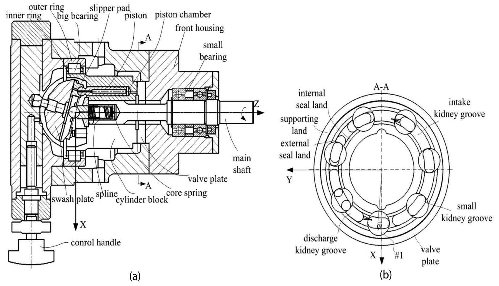
Figure 1 (a) Structure of the axial piston pump, (b) seven piston chambers.
The resultant force F along Z axis generated by the seven working piston chambers, and the torque M around X axis caused by the force F are described in the Equations (1) and (2). The torque M around Y axis is assumed to be zero because that its mean value in one period is nearly to be zero.
| (1) | ||
| (2) |
where p is the pressure in piston chambers, d is the inner diameter of piston chamber, Z is the number of piston chambers, R is the radius of distribution circle of piston chambers.
2.2 Forces and Torques of Valve Plate on Cylinder Block
The cylindrical coordinate system is established in Figure 2. The polar diameter of one point in the lubricating gap is r, the polar angle is , and the gap thickness is h. The wedge angle in Figure 2(a) is the angle between the valve plate and the matching surface of cylinder block, and the azimuth angle in Figure 2(b) is the angle between the polar axis and the line connecting the minimum and maximum gap thickness points. The minimum gap thickness point locates at the outer circumference of supporting land. However, the minimum oil film thickness point is at the outer circumference of external seal land.
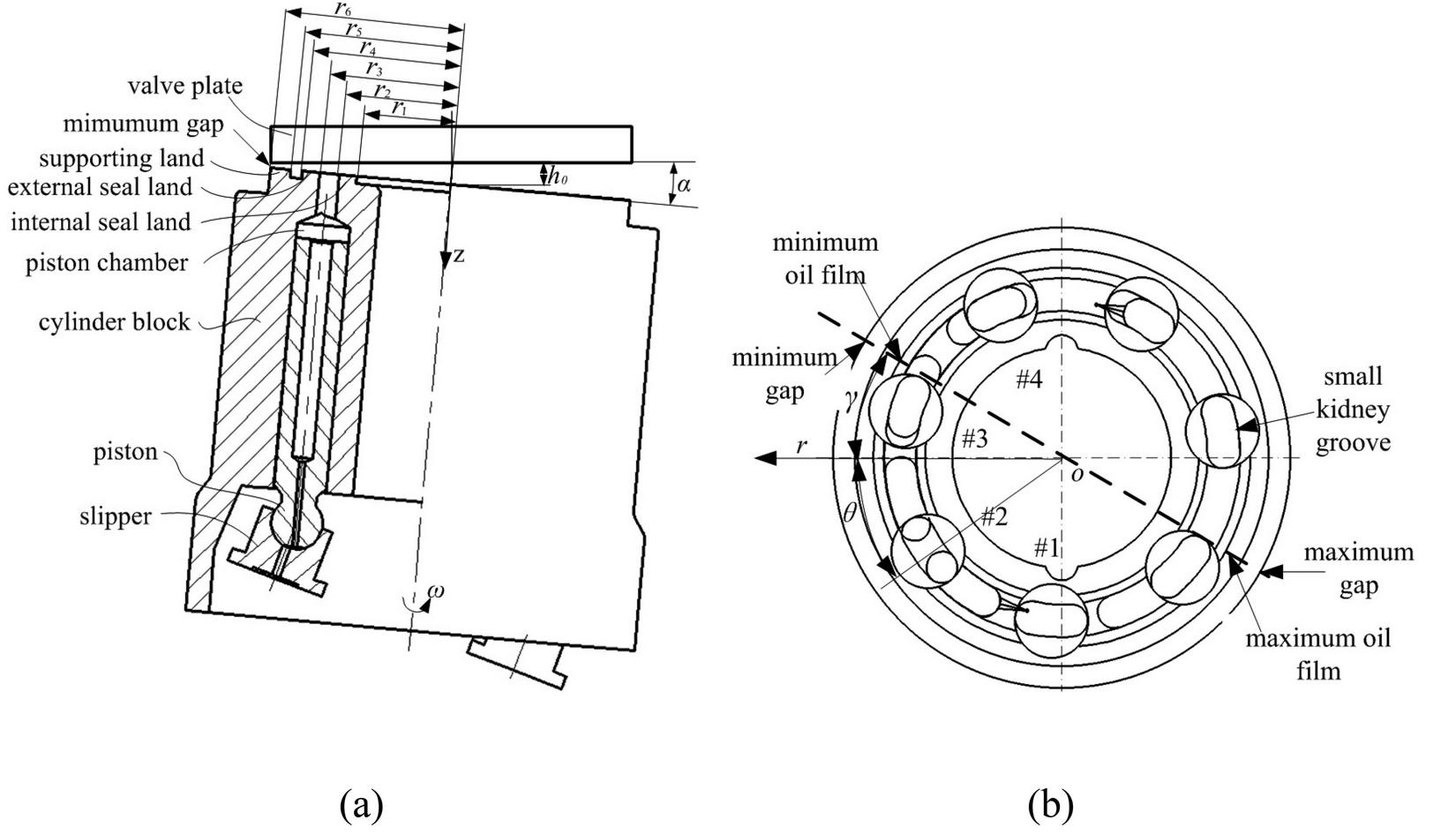
Figure 2 (a) the wedge angle of cylinder block with respect to valve plate, (b) the azimuth angle of the wedge gap.
The reaction force F of valve plate against cylinder block along Z axis, the torques M around X axis due to F are given in the Equations (3) and (4). And the torque M around Y axis is assumed to be zero because it is much less than M.
| (3) | ||
| (4) |
Where and respectively are the start and end angle values of the central angle of the high pressure working area of valve plate, r and r respectively are the inner diameter and outer diameter of the internal seal land of the discharge kidney groove, r and r respectively are the inner diameter and outer diameter of the external seal land of the discharge kidney groove.
2.3 Forces and Torques in Mixed Friction Area
The mixed friction between valve plate and cylinder block happens near the minimum gap thickness point. It is assumed that the surface roughness of the valve plate and cylinder block conform to Gaussian distribution. Assuming that the surface morphology parameters of the contact surfaces are same, the surface morphology of valve plate is measured by the surface profiler to determine the surface morphology parameters. The material of cylinder block is QT400, and that of valve plate is steel 45. The bearing capacity W of contact peaks in the mixed friction area, the force F along Z axis, the corresponding torques M around X axis and M around Y axis is given in the Equations (5)–(8).
| (5) | ||
| (6) | ||
| (7) | ||
| (8) |
Where n is the number of contact peaks per unit area, z is the height of rough peaks, and are the surface profile roughness of valve plate and equivalent roughness respectively, , R and respectively are the radius of rough peak of valve plate and the equivalent radius of rough peak of the contact surfaces, and are the start and end angle values of corresponding central angle of the mixed friction area, and , , are equivalent elastic modulus of valve plate and cylinder block surface materials.
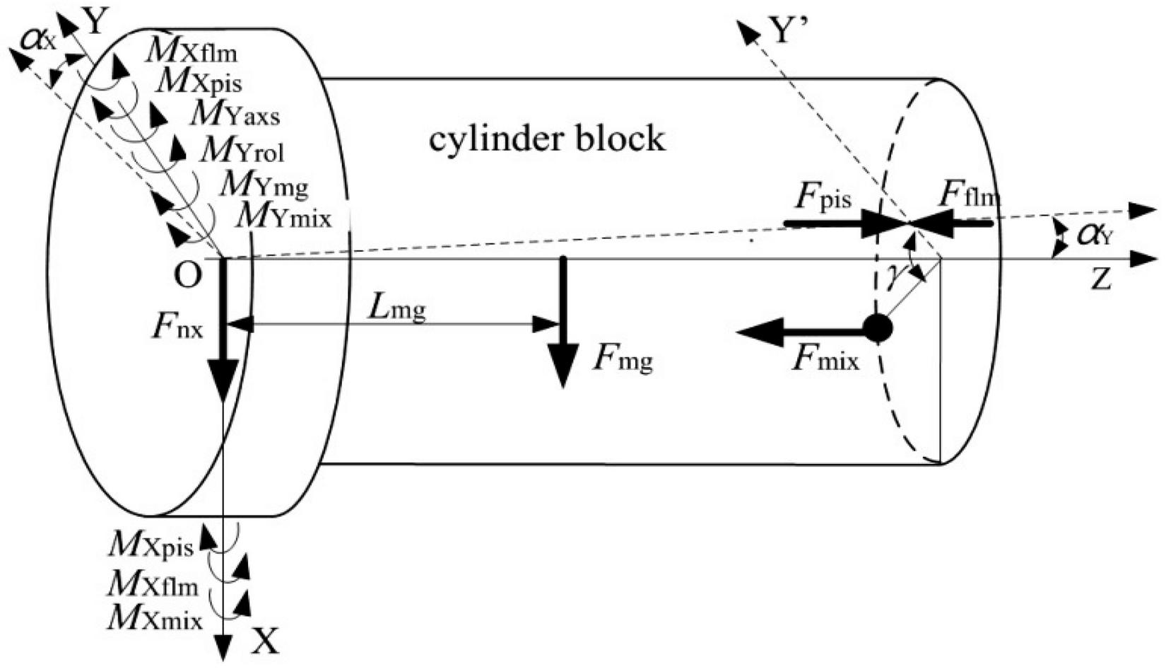
Figure 3 The forces and torques of cylinder block in three degrees of freedom.
2.4 Modelling of Wedge Angle and Azimuth Angle
For the wedge angle and azimuth angle of the lubricating gap, several assumptions are given below:
1. the valve plate is vertical to Z axis, and the cylinder block is inclined to the valve plate.
2. the torques M, M, M around X axis cause the cylinder block to rotate at a small angle around X axis, which is called X wedge angle with the symbol of . The corresponding azimuth angle of lubricating gap due to the torques around X axis is X azimuth angle with the symbol of , . The gap thickness in the outer circumference circle of supporting land is , and r is the outer diameter of supporting land of valve plate.
3. As shown in Figure 4, the force F between swash plate and cylinder block make the cylinder block move along positive X axis. The inner ring of the large bearing contacts with the roller, and the contact force between them is F. The inclination angle of cylinder block around Y axis caused by the torques around Y axis is named as Y wedge angle seen in the Equations (9) and (10). The corresponding azimuth angle of the lubricating gap is Y azimuth angle , , and gap thickness caused by the factor is .
| (9) | ||
| (10) |
where is the radial clearance of the big bearing, E is the elastic modulus of main shaft material, I is the inertia moment of main shaft, L is the distance between the right end face of spline fit and the left end face of roller shown in Figure 4, L is the distance between the right end face of spline fit and the left end face of small bearing shown in Figure 4, f is the deflection value at the point A when the inner ring of large bearing just touches the rollers. Meanwhile, refers to the inclination angle at the point A, which is the initial value of Y wedge angle. M refers to the torque around Y axis generated by the contact force F between cylinder block and roller. F is the gravity of the cylinder block. M refers to the torque generated by the gravity F. The torque M is caused by the supporting force F between cylinder block and valve plate.
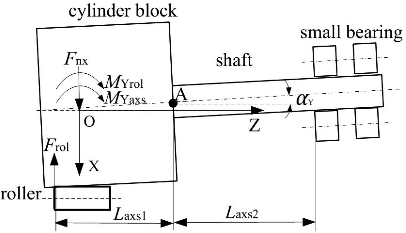
Figure 4 The Y wedge angle of cylinder block.
4. The inclination angle of cylinder block due to the torques around X and Y axes is called XY wedge angle , and the corresponding azimuth angle of the lubricating gap is XY azimuth angle .
5. Due to the coaxiality error between main shaft and cylinder block, an additional wedge angle appears between cylinder block and valve plate, the additional wedge angle is called Z wedge angle , and the corresponding azimuth angle is called Z azimuth angle . The wedge angle varies with the rotation of cylinder block and reaches a maximum when the azimuth angle equals to , and the cylinder block touches valve plate at the point A shown in Figure 5(a). However, the Z wedge angle reaches a minimum when the difference of and is , and the contact of them change from the point B to point C in Figure 5(b) because of the main shaft elastic bending by the torques around X and Y axes, and the wedge angle 2 reduces to zero. The gap thickness caused by the factor is .
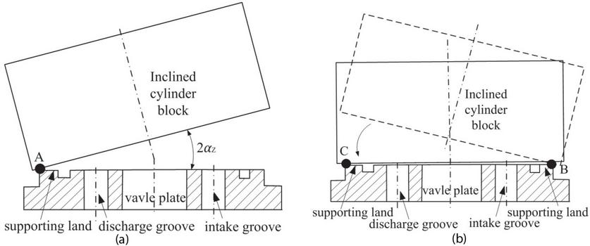
Figure 5 The wedge angle of lubricating gap caused by coaxiality errors.
6. In addition, the inclination angle of cylinder block is affected by other factors, especially eccentric wear of valve plate, as shown in Figure 6, the torque of the cylinder block makes itself contact with the valve plate on the side of discharge kidney groove. Thus the contact surfaces between them would be eccentric worn at the local area of the supporting land near the minimum gap point. The wedge angle owing to other factors, especially the eccentric wear is called wear wedge angle . The corresponding azimuth angle is wear azimuth angle . The gap thickness caused by the factor is .
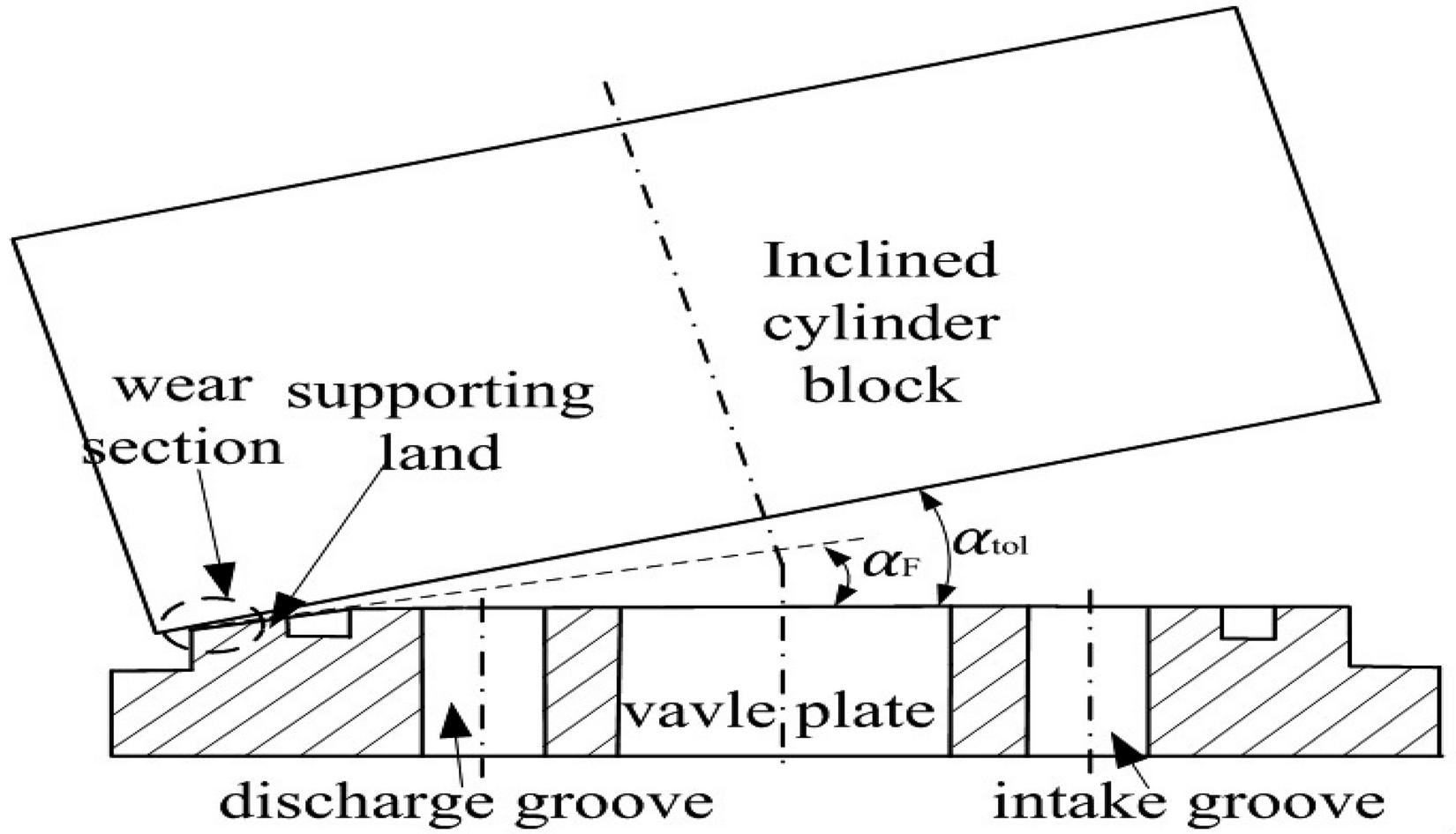
Figure 6 The wedge angle of lubricating gap caused by eccentric wear of the valve plate.
7. The wedge angle caused by all the above factors is named as total wedge angle . The corresponding azimuth angle is called total azimuth angle . The gap thickness at the outer circumference circle of the supporting land is , seen in the Equation (11).
| (11) |
where h is the minimum gap thickness.
8. The total wedge angle is , and h is the maximum gap thickness. The total azimuth angle is the angle between the polar axis and the line connecting the minimum and maximum gap thickness points.
9. The forces between the valve plate and the cylinder block make them close together. Assuming that the minimum gap thickness h equals to a constant, the gap thickness at a certain radius r of the valve plate is presented:
| (12) |
2.5 Force and Torque Balance Equations
Figure 3 shows the forces and torques on the cylinder block in three freedom degrees from the large bearing rollers, swash plate and valve plate, when the Z wedge angle and wear wedge angle are ignored. The force balance equation along Z axis, torque balance equations around X and Y axes are presented as follows:
| (13) |
2.6 Solution
The relevant parameters of the axial piston pump are shown in Table 1. The numerical calculation of the model is programmed by using MATLAB .mat file, and the solution of the proposed model is done.
Table 1 Key parameters of the axial piston pump
| r | [m] | 18.44 E-3 |
| r | [m] | 21.38 E-3 |
| r | [m] | 30.47 E-3 |
| r | [m] | 33.44 E-3 |
| r | [m] | 37.50 E-3 |
| r | [m] | 42.50 E-3 |
| D | [m] | 58.18 E-3 |
| d | [m] | 18.76 E-3 |
| n | [m] | 1.454E-11 |
| [m] | 1.2E-6 | |
| R | [m] | 1.89E-6 |
Considering FTB but ignoring CE and OTEW, the procedure for the calculation of the lubricating gap between valve plate and cylinder block is described in Figure 7.
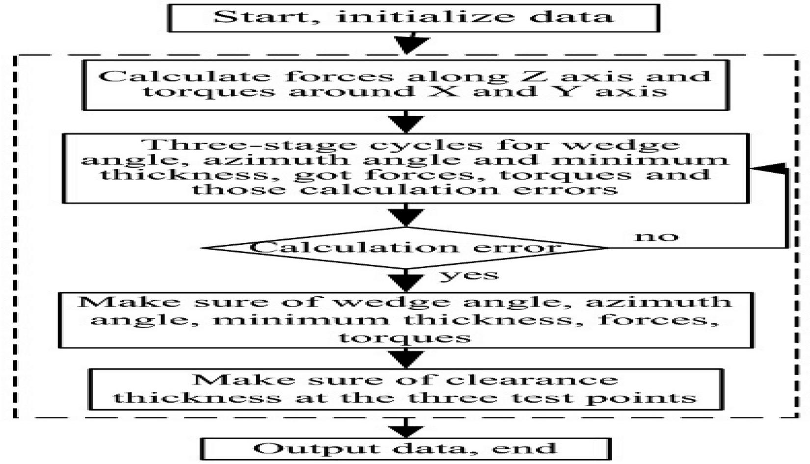
Figure 7 Flow chart of the numerical solution.
3 Experiment
In Figure 8, the gap thickness measurement and test system mainly includes power supply, frequency converter, motor, tested pump installed with three eddy current sensors, three shielding wires, three front ends, 24 VDC power supply, USB data acquisition card and computer. The four different working pressures of the test system are 3 Mpa, 5 MPa, 7 MPa, 9 Mpa, the two swash plate angles are 6.3, 14.3, and the working speed of the motor is 900r/min. In Figure 8(b), the sensors are installed at the circumferential positions T1, T2 and T3 of the valve plate respectively, the installation circle diameter is 76.2 mm. The three measuring points T3, T1 and T2 are located at the intake kidney groove side of the valve plate, and the corresponding central angles of them are 207, 267 and 333.5 respectively.
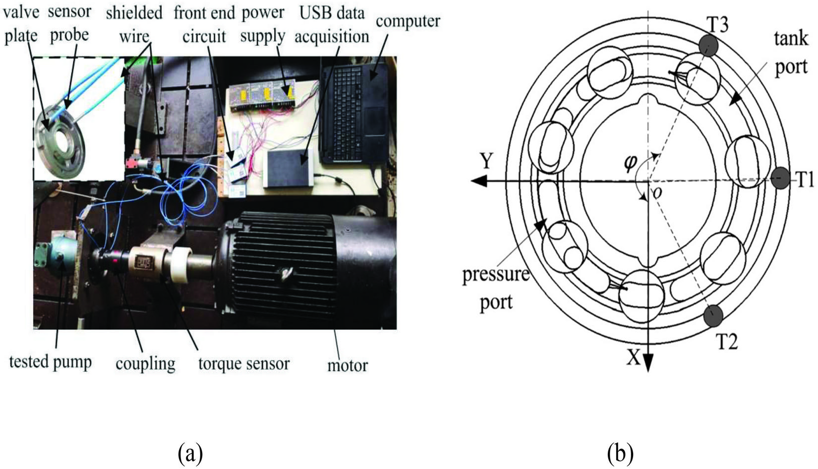
Figure 8 (a) the experimental system for measuring the micro gap film thickness, (b) the circumferential test positions A1A3 in the valve plate.
The fitting algorithm is used to analyze the test gap thickness data, and the numerical solution procedure of the fitting algorithm is shown in Figure 9.
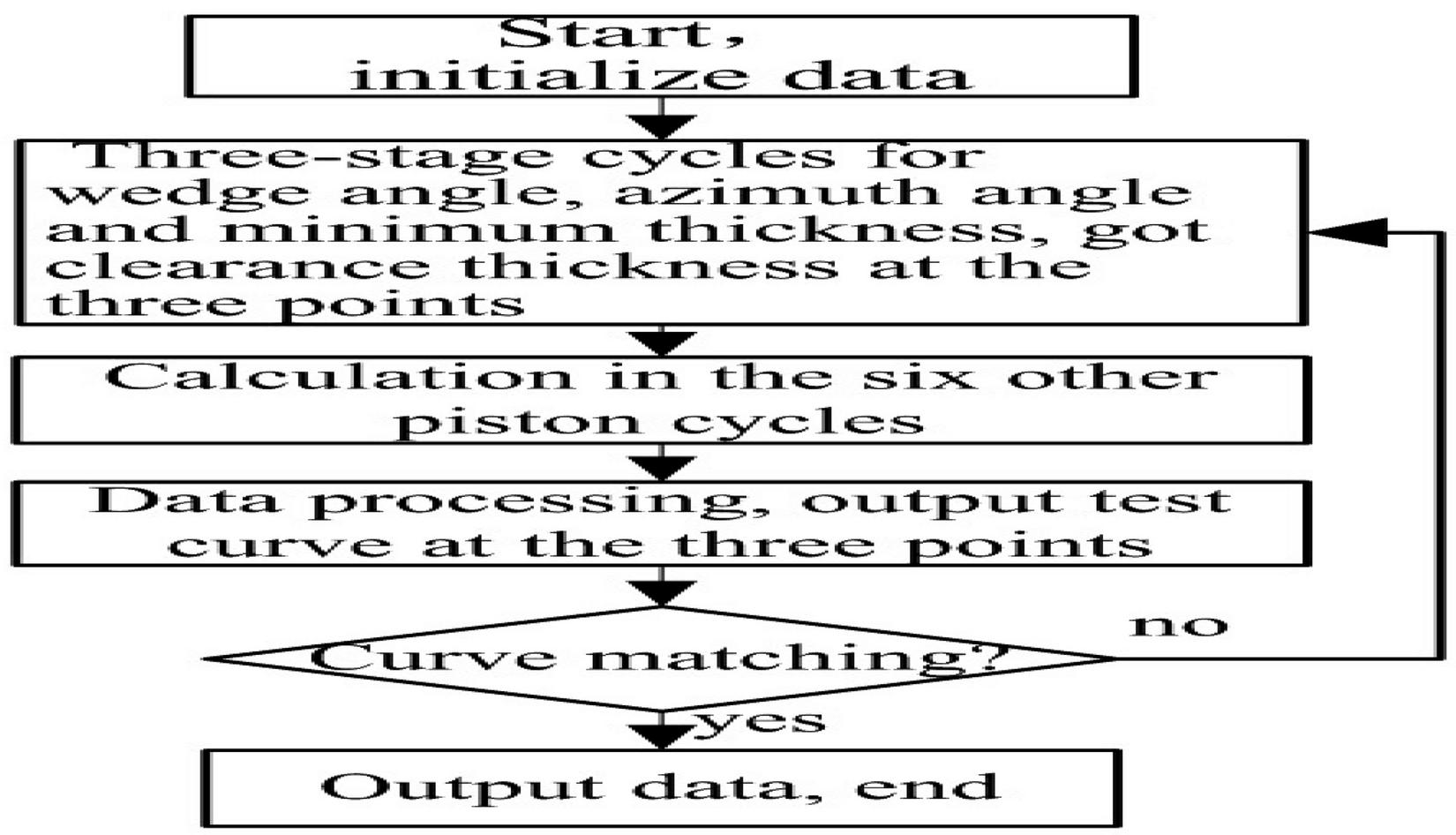
Figure 9 Flow chart of the fitting algorithm.
4 Results and Discussion
Figure 10 shows the gap thickness curves between valve plate and cylinder block at the test points T1, T2 and T3 under four different test conditions. The swash plate inclination angle is 6.3 and the working pressure is 3 Mpa under the condition 1, 6.3 and 9 Mpa under the condition 2, 14.3 and 3 Mpa under the condition 3, 14.3 and 9 Mpa under the condition 4. As shown in Figure 10, the curves T1, T2 and T3 are test curves, and the curves E1, E2 and E3 are the fitting curves got by the fitting algorithm.
The average gap thicknesses of curves T1, T2 and T3 under the condition 1 in Figure 10(a) are 110 um, 65 um, 88 um respectively, the fluctuation amplitudes of three curves are 30 um, 25 um, 23 um respectively. And the means of the Z wedge angle, wear wedge angle and total wedge angle are 1.65E-4, 1.195E-3 and 1.36E-3 respectively. The average gap thicknesses of curves T1, T2 and T3 under the condition 2 in Figure 10(b) are 113 um, 68 um, 85 um respectively, those fluctuation amplitudes are 113 um, 25 um, 22 um respectively, and the means of Z wedge angle, wear wedge angle and total wedge angle are 1.65E-4, 1.225E-3 and 1.39E-3 respectively. The average thickness values of curves T1, T2 and T3 under the condition 3 in Figure 10(c) are 115 um, 50 um and 110 um respectively, those fluctuation amplitudes 74 um, 42 um and 67 um respectively, and the means of Z wedge angle, wear wedge angle and total wedge angle 3.5E-4, 1.25E-3 and 1.60E-3 respectively. Similarly, the average thickness values of them under the condition 4 in Figure 10(d) are 125 um, 70 um and 120 um respectively, those fluctuation amplitudes 80 um, 43 um and 70 um respectively, and the means 4.3E-4, 1.41E-3 and 1.84E-3 respectively. Obviously, the means of gap thickness and fluctuation amplitude of the three test points under the condition 1 are close to those under the condition 2. And, the means of gap thickness under the conditions 3 are similar to those under the condition 4. It is indicated that the swash plate angle has a greater impact on the total wedge angle and total azimuth angle of the lubricating gap than the working pressure.
The fitting curves E1, E2, E3 under the conditions 1 and 2 meet well with the test curves T1, T2 and T3 respectively, all of those curves like trigonometric function curves. However, there are phase differences between the test curves and the fitting curves under the conditions 3 and 4. The means of curves T1 and T3 under the condition 3 are slightly smaller than those under the condition 4, which indicates that the total wedge angle gradually increases with the increase of pressure. And, the difference between the means of curve T1 and curve T3 under the condition 3 is slightly larger than that under the condition 4, which indicates that the minimum thickness point moves toward the positive Y axis.
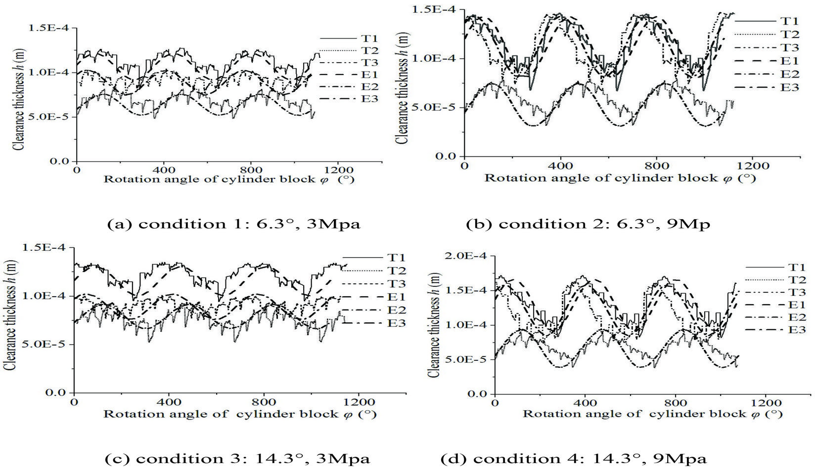
Figure 10 The gap thickness curves at test points T1, T2 and T3.
Figure 11 shows the theoretical and experimental curves of the total wedge angle of the lubricating gap. The XY wedge angle almost doesn’t change with the increase of pressure when the swash plate angle is 6.3 or 14.3, and is about 1.2E-4. The test value of the Z wedge angle hardly varies with the increase of working pressure at 6.3, is about 1.65E-4, and which slightly increases from 3.5E-4 to 4.3E-4 with the rise of pressure from 3 MPa to 9 MPa. Obviously, the test value of total wedge angle is greater than its theoretical value by the Equation (11), then, the Equation (11) is used to determine the wear wedge angle . The wear wedge angle is nearly 1.35E-3 with the enlargement of pressure from 3 MPa to 9 MPa at 6.3, and slightly increases from 1.25 E-3 to 1.41E-3 at 14.3. It indicates that the wear degree of supporting land is nearly same on the side of the discharge kidney groove. It is concluded that CE and OTEW are the important factors affecting the total wedge angle of the lubricating gap. Therefore, reduction of the coaxiality error and improvement of the wear resistance of the surface materials of valve plate would largely reduce leakage amount between cylinder block and valve plate.
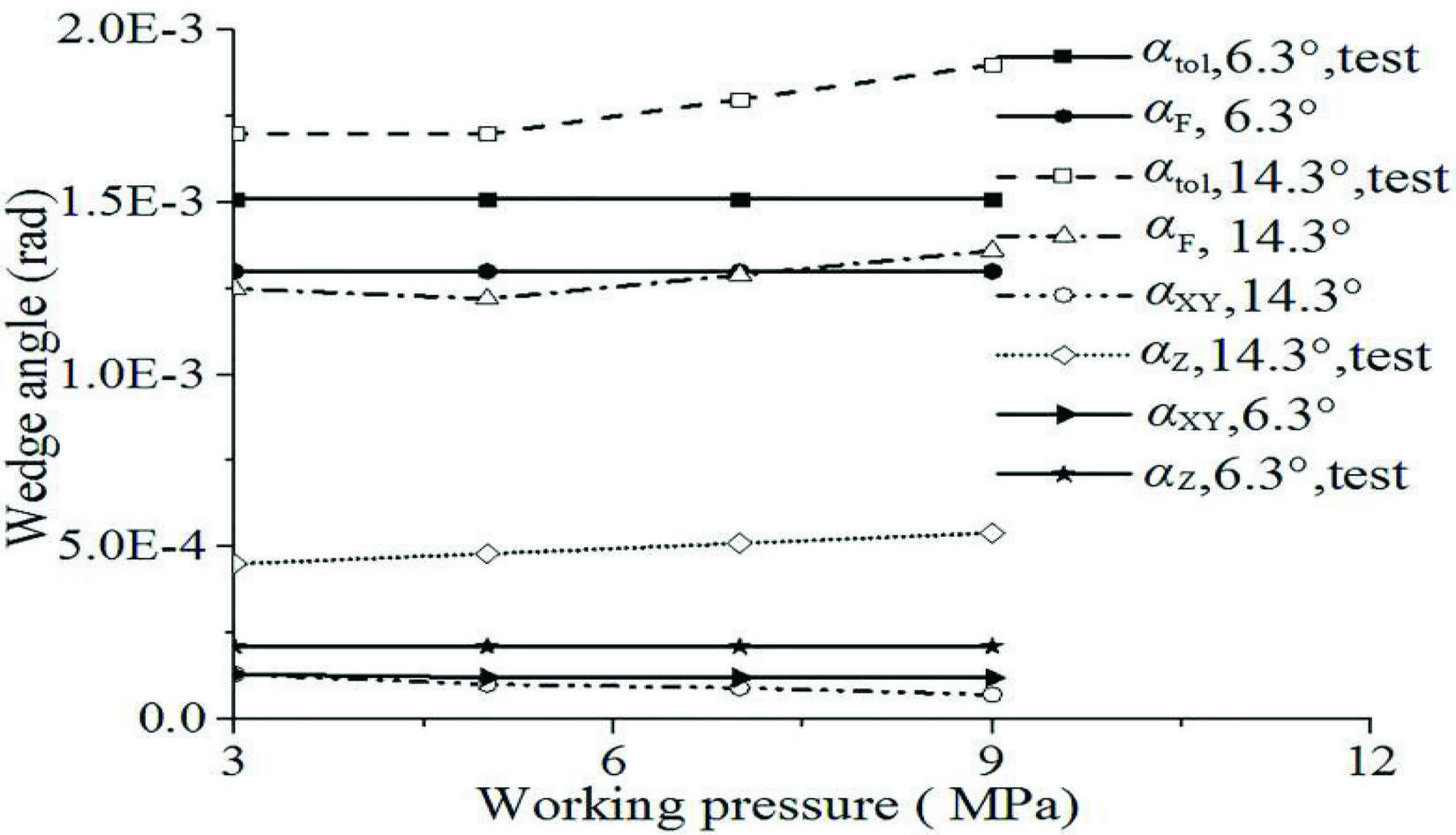
Figure 11 The gap thickness curves at test points T1, T2 and T3.
Figure 12 shows the fitting curves of the total wedge angle of the gap thickness in one cycle of . In the figure, the four total wedge angle curves have the same trend, liking a trigonometric function curve with a cycle period of 360. In the conditions 1 and 2, the total wedge angle curves almost coincide, slightly different from each other, and the fluctuation amplitude of the curves is about 4.2E-4, therefore, the Z wedge angle is 2.1E-4. The total wedge angle curves under the conditions 3 and 4 are close to each other, the total wedge angle of condition 4 is slightly larger than that of condition 3, and the difference of them is about 2.0E-4, indicating that the Z wedge angle increases with the increase of working pressure. The mean of the total wedge angle of condition 4 is about 1.9E-3, and its fluctuation amplitude is about 8E-4. It is obvious that the mean and fluctuation value of the total wedge angle under the conditions 3 and 4 are larger than those under the conditions 1 and 2, therefore, the displacement of the tested pump has a greater influence than the working pressure on the total wedge angle.
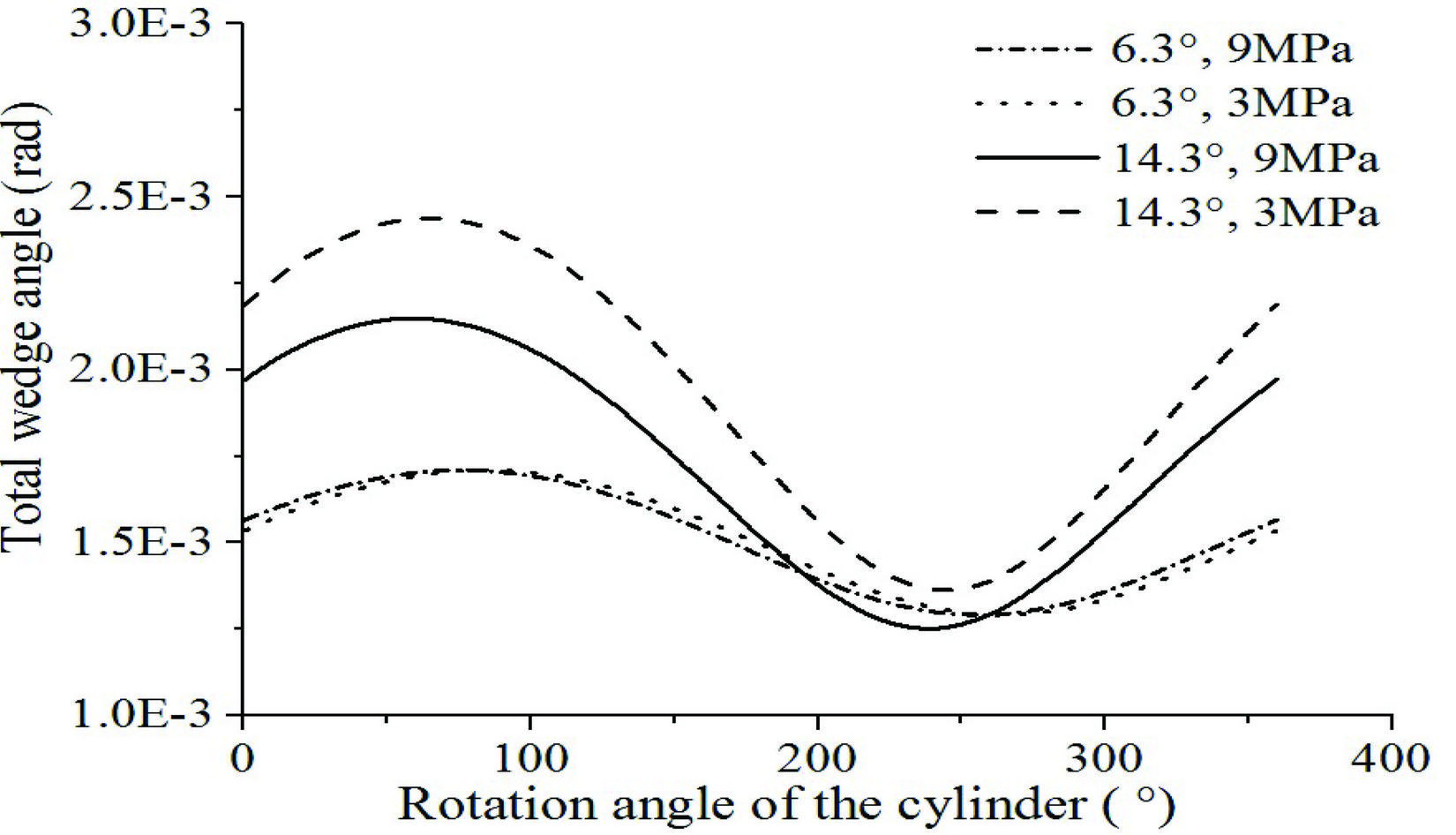
Figure 12 The total wedge angle curves in one cycle.

Figure 13 The total azimuth angle curves in one cycle.
Figure 13 shows the fitting curves of the total azimuth angle in one cycle of . The total azimuth angle curves under the four conditions are trigonometric function curves with a period of 360. The trends of the total azimuth angle curves are similar under the conditions 1 and 2, and the mean of them are about 10 and 18 respectively, and the fluctuation amplitudes are about 15. The trends of the total azimuth curves under the conditions 3 and 4 are similar, the average values of them are 17 and 22 respectively, and the fluctuation amplitudes are about 25. It is seen that the mean of the total azimuth angle decreases and the fluctuation amplitude increases with the increase of the wedge angle of the swash plate, and the mean of the total azimuth angle decreases and the fluctuation amplitude remains unchanged with the increase of the working pressure.
Figure 14 shows the measured distance between the barrel plate aluminium disk and the port plate when the swash plate angle of tested pump is 20 degrees and the working pressure of tested hydraulic system is 2.5MPa [2]. By the presented model, the total wedge angle of the gap film for the test curves in Figure 14 is above 7E-4, the XY wedge angle due to FTB is about 1.5E-4, the test value of the Z wedge angle is 1.35E-4, and the wear wedge angle is about 4.5E-4. It is clear that OTEW are the more important factors than FTB and CE affecting the wedge angle of the lubricating gap film.
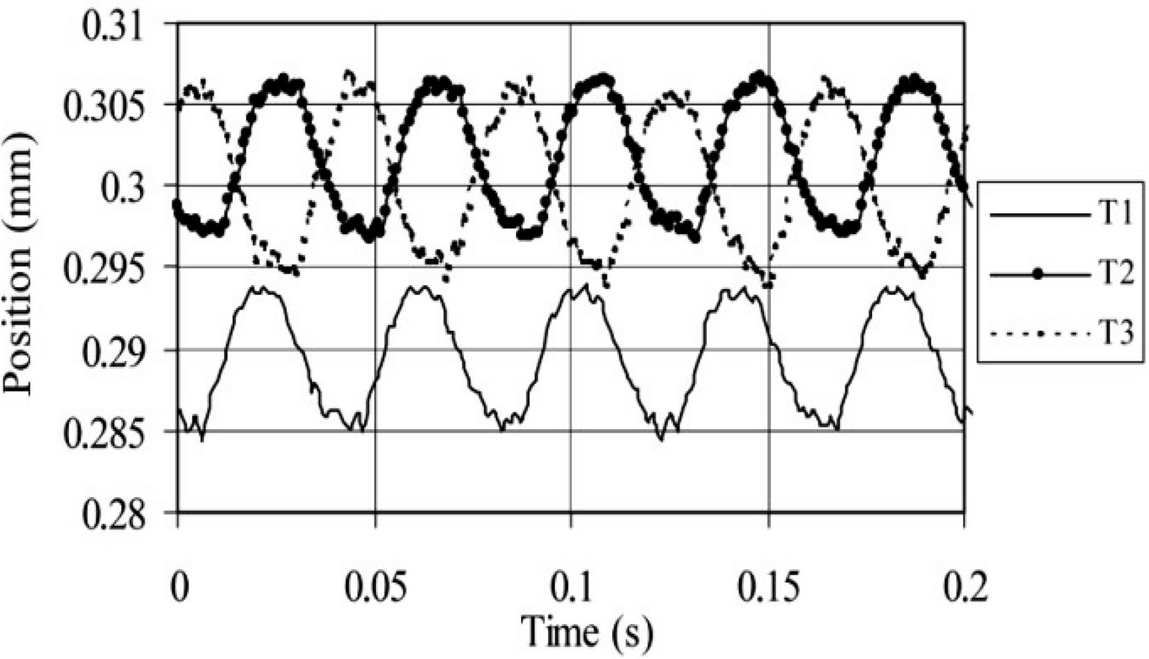
Figure 14 The measured distance between the barrel plate aluminium disk and the port plate.
5 Conclusions
The conclusions are drawn as follows,
1. The factors of FTB, CE and OTEW and their effect on the wedge angle and azimuth angle of lubricating gap between cylinder block and valve plate are analyzed. Several new wedge angles and azimuth angles are defined, and the new trigonometric function model of the lubricating gap geometry is established.
2. The XY wedge angle due to FTB by the model is about 1.2E-4, the Z wedge angle owning to CE by test 1.65E-44.3E-4, the wedge angle resulting from OTEW by model is about 1.35E-3, and the test total wedge angle by the above four factors is 1.35E-31.85E-3. Obviously, CE and OTEW have larger influence than FTB on the total wedge angle of lubricating gap. Therefore, reduction of the coaxiality error and improvement of the wear resistance of the surface materials of valve plate would largely reduce leakage amount between cylinder block and valve plate.
3. The Eddy current sensors are utilized to acquire the gap thickness under different pressures and swash plate angles in the experiment. The experimental results show that the total wedge angle obviously increases with the enlargement of swash plate angle but slightly rises with the increasing working pressure. Therefore, the swash plate angle has a stronger impact than the working pressure on the total wedge angle.
Acknowledgments
This work was supported by the [National Natural Science Foundation of China] under Grant [number 51605320]; [the Key Research and Development Projects of Shanxi province] under Grant [number 201903D121077]; and [the Open Research Fund of State Key Laboratory of High Performance Complex Manufacturing of Central South University] under Grant [number Kfkt2018-13].
Nomenclature
| F | Force | [N] |
| M | Torque | [Nm] |
| A | Area | [m] |
| R | Radius | [m] |
| L | Length | [m] |
| I | Inertia moment | [m] |
| K | Spring stiffness | [Nm] |
| L | Length | [m] |
| r | Radius | [m] |
| d | Diameter | [m] |
| E | Bulk modulus | [Pa] |
| p | Pressure | [Pa] |
| h | Gap thickness | [m] |
| Polar angle | [rad] | |
| Wedge angle | [rad] | |
| Azimuth angle | [rad] | |
| Z | Number of piston chambers | |
| r | Inner diameter of internal seal land | [m] |
| r | Outer diameter of internal seal land | [m] |
| r | Inner diameter of external seal land | [m] |
| r | Outer diameter of external seal land | [m] |
| r | Inner diameter of supporting land | [m] |
| r | Outer diameter of supporting land | [m] |
| n | Number of contact peaks per unit area | [m] |
| z | Height of rough peaks | [m] |
| Surface roughness | [m] | |
| F | Force along positive X axis | [N] |
| Radial clearance of the big bearing | [m] | |
| f | deflection value at the point A | [m] |
| inclination angle at the point A | [rad] |
Frequently used indices
| P | Discharge pressure |
| X | X axis |
| Y | Y axis |
| Z | Z axis |
| F | Wear |
| tol | total thickness/angle |
| pis | Piston chamber |
| flm | Oil film |
| mix | Mixed friction |
| i | Start angle value |
| j | End angle value |
| e | Equivalent roughness/radius |
| vlv | Valve plate |
| rol | Roller |
| mg | Gravity of cylinder block |
| axs | Force/torque on the main shaft |
| max | Maximum thickness |
| min | Minimum thickness |
References
[1] Ivantysynova, M. 1999. A new approach to the design of sealing and bearing gaps of displacement machines. Proceedings of the Forth JHPS International Symposium on Fluid Power, pp. 45–50, Tokyo, Japan.
[2] Kazama, T., Sasaki, H. and Narita, Y. 2010. Simultaneous temperature measurements of bearing and seal parts of a swash plate type axial piston pump—effects of piston clearance and fluid property. Journal of Mechanical Science and Technology, Vol. 24(6), pp. 203–206.
[3] Dhar, S. and Vacca, A. 2012. A novel CFD–Axial motion coupled model for the axial balance of lateral bushings in external gear machines. Simulation Modelling Practice and Theory, Vol. 26, pp. 60–76.
[4] Dhar, S. and Vacca, A. 2015. A novel FSI–thermal coupled TEHD model and experimental validation through indirect film thickness measurements for the lubricating interface in external gear machines. Tribology International, Vol. 82, pp. 162–175.
[5] Bergada, J. M., Kumar, S., Davies, D. L. and Watton, J. 2012. A complete analysis of axial piston pump leakage and output flow ripples. Applied Mathematical Modelling, Vol. 36, pp. 1731–1751.
[6] Bergada, J. M., Watton, J. and Kumar, S. 2008. Pressure, flow, force, and torque between the barrel and port plate in an axial piston pump. Journal of Dynamic Systems Measurement and Control-Transactions of the ASME, Vol. 130(1), pp. 11011/1–16.
[7] Bergada, J. M., Davies, D. L. and Kumar, S. 2012. The effect of oil pressure and temperature on barrel film thickness and barrel dynamics of an axial piston pump. Meccanica, Vol. 47 (6), pp. 639–654.
[8] Shin, J. H., Kim, H. E. and Kim, K. W. 2011. Lubrication analysis of the thrust bearing in the valve plate of a swash-plate type axial piston. Proceedings of the ASME/STLE 2011 IJTC, pp. 199–201, Los Angeles, California, USA.
[9] Zloto, T., Sochacki, D. and Stryjewski, P. 2014. Analysis of oil leaks in a variable-height gap between the cylinder block and the valve plate in a piston pump by means of author-designed software and CFD Fluent. TEKA. Commission of Motorization and Energetics in Agriculture, Vol. 14 (4), pp. 211–216.
[10] Zloto, T., Sochacki, D. and Stryjewski, P. 2014. Analysis of oil leaks in a variable-height gap between the cylinder block and the valve plate in a piston pump by means of author-designed software and CFD Fluent. TEKA. Commission of Motorization and Energetics in Agriculture, Vol. 14, pp. 211–216.
[11] Shang, L. and Ivantysynova, M. 2016. An Investigation of Design Parameters Influencing the Fluid Film Behavior in Scaled Cylinder Block/Valve Plate Interface. Proceedings of the 9th FPNI Ph.D. Symposium on Fluid Power, pp. 1–10, Florianópolis, SC, Brazil.
[12] Manring, N.D. 2000. Tipping the cylinder block of an axial-piston swashplate type hydrostatic machine. Journal of Dynamic Systems Measurement and Control-Transactions of the ASME. Vol. 122, pp. 216–221.
[13] Yamaguchi, A. 1986. Formation of a fluid film between a valve plate and a cylinder block of piston pumps and motors (Ist report, A valve plate with hydrodynamic pads). Bulletin of the JSME, Vol. 29, pp. 1494–1498.
Biographies

Zhiqiang Zhang Born on July 1982 in Weifang (China). PhD. in Material Processing Engineering from Taiyuan University of Science and Technology, Taiyuan, China, 2014. Associate professor of School of Mechanical Engineering, Taiyuan University of Science and Technology. Research interests include modelling and numerical simulation of hydraulic pumps, valves and circuit systems.

Haitao Yuan Born on December 1995 in Xianyang (China). Bachelor in School of Mechanical Engineering from Taiyuan University of Science and Technology, Taiyuan, China, 2018. Postgradute of School of Mechanical Engineering, Taiyuan University of Science and Technology. Research interests include modelling and numerical simulation of hydraulic pumps.

JianLi Song Born on October 1969 in Shanxi (China). Ph.D. in the School of Mechanical Engineering from Shanghai Jiao Tong University, ShangHai, China, 2006. Professor of the School of Instrument Science and Opto-Electronics Engineering, Beijing Information Science and Technology University, Beijing, China. Doctoral supervisor of Taiyuan University of Science and Technology, TaiYuan, China. Research interests mainly include advanced manufacturing technology.

Haibo Zhou Born on 1981 in China. Ph.D. in mechanical and electrical engineering from Central South University, Changsha, China, 2010. Professor of the School of Mechanical and Electrical Engineering, Central South University. Visiting Ph.D. student in Wayne State University, Detroit, USA, 2007–2008. Research interests include theory and application of fuzzy intelligent control, ultra-precision motion design. Member of the IEEE Computational Intelligence Society.
International Journal of Fluid Power, Vol. 21_2, 211–234.
doi: 10.13052/ijfp1439-9776.2123
© 2020 River Publishers