A Digital Displacement Hydrostatic Wind-turbine Transmission
Win Rampen1,*, Daniil Dumnov2, Jamie Taylor2, Henry Dodson2, John Hutcheson2 and Niall Caldwell2
1School of Engineering, University of Edinburgh, Mayfield Road, Edinburgh EH9 3FB, Scotland
2Artemis Intelligent Power Ltd., Unit 3 Edgefield Road Industrial Estate, Loanhead EH20 9TB, United Kingdom
E-mail: W.Rampen@ed.ac.uk
*Corresponding Author
Received 25 September 2020; Accepted 30 January 2021; Publication 27 April 2021
Abstract
In 1984 a hydrostatic wind-turbine transmission with ‘secondary control’ was proposed by Stephen Salter using the, then only conceptual, Digital Displacement® (DD) principle for controlling the flow of the primary, rotor-driven, ring-cam pump. This transmission ‘could achieve the correct ratio of tip-speed to wind-speed in conjunction with true synchronous generation’.
In the following years DD machines were progressively developed. To start with they were relatively small in capacity but the power ratings were systematically increased, until it seemed that a high-power hydrostatic wind-turbine transmission might indeed be feasible. In 2006, Artemis Intelligent Power (Artemis), a company that had been formed from Salter’s original University of Edinburgh team, began working on a megawatt-scale, hydrostatic, wind-turbine transmission based on new pump and motor designs. In 2011 Artemis completed a 1.5 MW transmission and dynamometer test-rig. This was one of the largest hydraulic transmissions ever made and, with a shaft-to-shaft efficiency of 93%, one of the most efficient. Using secondary control to respond rapidly to gusting wind and to instantaneous grid faults, it was also the most controllable. This paper discusses the design of the transmission and test-rig and presents the results of steady-state efficiency tests. Subsequent papers will describe systematic experimental work to account for the various energy losses and to develop a comprehensive simulation model of the DD wind-transmission.
Keywords: Digital displacement, hydraulic transmission, hydrostatic transmission, ring-cam pump, wind-turbine.
Introduction
Some early wind turbines were built with fluid power transmissions. Two examples, respectively from 1977 and 1980, are the 30 kW Lawson-Tancred turbine (Lawson-Tancred, 1984) and the 3 MW Bendix SWT-3 machine (Rybak, 1982). In 2008, Chapdrive created a 900 kW system (Thomsen et al., 2012) and in 2014 Vestas Wind Systems A/S published a patent relating to the control of hydrostatic transmissions in wind turbines (Lindholdt et al., 2014).
The cube-law relationship between wind-speed and wind power implies that, if it is to be economically viable, a wind-turbine transmission has to be highly efficient and controllable over a wide range of rotor speeds and power levels. In a hydrostatic system, this level of performance is only possible if both the pump that collects energy from the rotor and the motor that delivers it on to the generator are variable-displacement types. None of the early examples cited above had this ‘secondary control’ capability (although the Bendix turbine used a stepped displacement arrangement on the low-speed end). Salter (1984) grasped this fundamental challenge and saw the need to reinvent variable-displacement hydraulic machines such that they would have higher part-load efficiencies than those available at the time.
Starting in 2006, Artemis addressed the challenge of developing a rugged, variable-speed transmission system that could supply shaft power to a conventional synchronous generator at power levels up to and above 10 MW with all parts of the system still being economically serviceable at remote offshore locations.
From the beginning, the inclusion of a wound-rotor synchronous generator as part of the drive-line was part of the design specification. These are better than any other type of generator at handling network fault conditions and they have long been the electrical work-horses of conventional fossil and nuclear-fuelled power stations (Say, 1983; Freris and Infield, 2008). Both their close-coupled inertia and their ability to supply controlled amounts of reactive power make them helpful for network stability. Unlike the generators of most wind-turbines they connect directly to the electrical network without costly high-power electronics, but this connection can only be made when the generator is already spinning at a speed that matches the network frequency and with both sets of voltages in close phase agreement. No wind-turbine transmission other than the DD system described here has demonstrated the ability to do this rapidly and automatically. Once connected, the generator speed is locked to the network frequency with its ‘load angle’ advancing or retarding, as more or less electrical power is delivered.
Digital Displacement Technology
The fundamentals of DD technology have been described in detail elsewhere (Rampen, 1992; Ehsan, 2000; Rampen et al., 2006). It comprises a new class of hydraulic machine suitable for closely-controlled, efficiency-sensitive, applications. It was created by systematically addressing the loss mechanisms of existing variable-displacement axial-piston machines. These typically use a variable-angle swash-plate to change the length of piston strokes and a mechanical commutator mechanism to alternately switch cylinders between the intake and outflow ports. As the cylinders are pressurised on every working cycle the energy losses due to leakage and compressibility do not reduce proportionally with the load on the machine. Most of this leakage is, by design, being used to maintain separation between heavily loaded surfaces, but it exacts a high price in the form of energy losses.
In contrast, each cylinder of a DD machine has its own discrete low-pressure (LP) and high-pressure (HP) valve. In a DD pump these comprise a solenoid-activated LP valve and a passive HP check-valve, whilst in a DD motor both the LP and the HP valve are solenoid-activated. Individual cylinders are pressurised only when the embedded controller asserts that a contribution to the net flow or torque of the machine is going to be required during the piston stroke that is about to start. If not thus enabled, the LP valve stays open and the cylinder continues to ‘idle’ with very low leakage losses. Scheduling cylinder pressurisation in this way transforms both controllability and part-load efficiency and allows the topology of the machine to be improved so that energy losses can be reduced to an absolute minimum.
In DD machines, the areas and relative velocities of high-speed, heavily-loaded, bearing surfaces are minimised by the use of radial, rather than axial, piston architecture and through the elimination of the traditional flow-commutating port-plate. The largest hydrodynamically-supported bearing element in the machine is the individual piston-pad. This allows the piston to be greatly increased in size and capacity before its shape is so distorted by pressure-induced strains that the lubricating-films are disrupted. The net machine displacements and power ratings are increased by over an order of magnitude above conventional practice, a possibility that Salter had predicted in 1984, when he saw the future feasibility of 30 MW hydrostatic wind-turbine transmissions.
The fluid passages through conventional commutator ports are necessarily constricted to achieve hydrostatic balance on the cylinder, with consequences in pressure drop at higher speeds. Removing the need for the port-plate and positioning the computer-controlled, solenoid-operated valves around the relatively spacious perimeter of the machine reduces breathing-losses.
Since close pressure equalisation is required before they can be opened, the solenoid-driven face-seating DD valves eliminate compressibility losses and remove the irritating whine that is often associated with hydraulic machines.
The result of these changes has been a new class of machine with fixed-length strokes and electromagnetically-selectable valves that can be controlled on a stroke-by-stroke basis to alter the action of individual cylinders on the fly. By default, every cylinder idles but can be individually selected to pump or motor as required. When idling, they remain at low-pressure with insignificant leakage losses and with low bearing loads. Early experimental machines, with all cylinders idling, demonstrated parasitic losses of less than one percent of the full rated power of the machine.
Development of DD machines began in 1987 at the University of Edinburgh and from 1994 was continued by the spin-out company Artemis Intelligent Power. It grew by licensing DD technology to established companies, working with them to develop pump and motor components of increasing size and demonstrating a wide range of applications.
In 2007, with financial support from Carbon Trust, Artemis began designing a hydrostatic transmission that would be suitable for a 1.5 MW wind-turbine, the most common power rating at that time. In 2009, the UK Government’s Department of Energy and Climate Change (DECC) began to support this work. In late 2010, Mitsubishi Heavy Industries of Japan acquired Artemis and further funded the building of a bespoke dynamometer that would allow the transmission to be tested and demonstrated at varying input speed and power levels.
This paper describes the processes of designing, building, commissioning and initial testing of the laboratory prototype 1.5 MW wind-turbine transmission.
The DD Transmission
Figure 1 is a simplified schematic of the 1.5 MW hydrostatic wind-turbine transmission. It comprises a rotor-driven, low-speed, DD pump and two DD motors, each of which drives a separate synchronous generator. A gas accumulator, a device for storing hydraulic energy, is connected to the HP line between the pump and the motors. A matching LP accumulator on the ‘return’ side of the circuit provides a local source and sink for changes in the active oil volume as the HP accumulator absorbs and releases energy. For safety, and to avoid over-stressing of hydraulic components, a pressure-relief-valve limits the maximum system pressure.
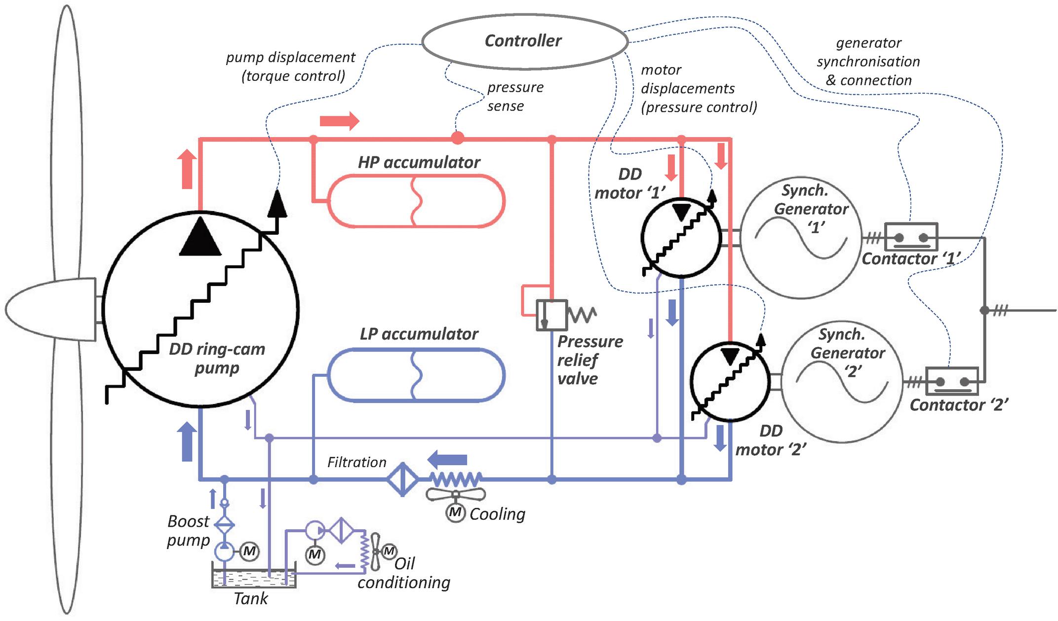
Figure 1 Simplified schematic of the Digital Displacement wind-turbine transmission.
On the LP side of the circuit a cooler and a return-line filter ensure that relatively cool, clean oil returns to the intake of the DD pump. Drain lines from the DD pump and DD motor casings return oil to the reservoir tank at atmospheric pressure. To ensure long life of both the oil and the mechanical components, an off-line filtration system continually processes the reservoir oil to remove water and debris. A boost pump from the reservoir charges the LP side to a nominal 5 bar to eliminate cavitation issues in the fluid circuit.
The gas accumulator is a key element of the transmission concept. For simplicity, it is shown in Figure 1 as a single unit, but is in fact a combination of discrete accumulators attached to different parts of the system. Collectively, these provide a compliant energy store, whose storage level is entirely a function of the current system operating pressure and of the individual gas pre-charge pressures. The amount of energy stored, typically equivalent to only seconds at full power, is less important than the decoupling that the accumulator compliance provides between the input and output stages of the driveline. This energy buffering is analogous to a low-pass filter in a signal-processing context and is essential for system control. It allows DD pump torque to respond quickly to changing wind-speed and turbulence whilst either or both of the DD motors drives its generator at a more slowly-varying averaged power level.
The DD pump is connected directly to the wind-driven rotor and comprises two axially-adjacent ‘banks’ of 34 cylinders, each with its own 24-lobe cam-ring. These figures were chosen to provide a high number of separately controllable, overlapping pumping cycles for each shaft revolution but with every pair of diametrically opposing cylinders in phase with one another so that their radial shaft-bearing loads cancel out. The two cam-rings are rotationally out of phase by half of a ‘wavelength’ so that enabling decisions for each of the pump’s 34 pairs of radially-opposing cylinders occur 34 24, or 816, times per shaft revolution, approximately every 0.44 degrees. The DD pump can ramp from zero displacement to full flow and full torque, or the reverse, in half of a cam cycle, 1/48 of a shaft revolution or 7.5 degrees. This is also the nominal angular duration of each individual pumping stroke.
In terms of the speed of response, at a typical shaft-speed of 10 rpm, cylinder-enabling decisions occur at 7.35 ms intervals and the durations of full displacement ramps and of individual pumping strokes are 125 ms.
In the default idle mode, the LP valve of each cylinder remains open at the end of each fluid intake stroke and unpressurised oil is simply returned to the LP manifold. In pumping mode, when the cylinder is required to contribute to the load torque on the rotor, its LP valve is closed at bottom-dead-centre by the pump’s embedded controller so that its piston pressurises and delivers the fluid through the HP check-valve to the DD motor circuit.
At the other end of the driveline are two DD motors, each driving a separate generator. As offshore wind-turbines typically report annual capacity factors of less than 50%, (Smith, 2020) usually only one of these needs to be active, marginally raising net efficiency compared with a single larger generator. This configuration also confers a useful level of redundancy. The generators run at a constant synchronous speed that is locked to the network frequency. Increasing or decreasing the displacement of the DD motors changes the motor torque, thus advancing or retarding the load-angles of the generators and increasing or decreasing the electrical power exported to the network.
Concurrently with commissioning the DD wind-transmission, the automated synchronisation of a four-pole 445 kVA synchronous generator was demonstrated on a smaller test-rig. From standstill a DD motor, similar to those used in the wind-transmission, accelerated, synchronised and connected the generator to the network in less than ten seconds. Fast acceleration to 1500 rpm and then fine speed-modulation to bring the generator into phase with the network was possible because of the inherently low inertia of the DD motor, typically an order of magnitude less than that of the generator, and the rapid and precise torque-control provided by DD technology.
In the event of sudden loss of generator load, such as through a network fault, the rotor blades will immediately start to be pitched back in angle to reduce the absorption of wind energy. In the meantime, the decelerating rotor continues to be loaded by the DD pump, with the energy being stored in the HP accumulators and, if necessary, dissipated by the pressure-relief-valve. The disconnected generators can be kept spinning at network frequency by the DD motors. For a typical transient fault, it will then only take seconds to re-synchronise the generators and reconnect to the restored network. If the fault persists, the rotor will complete its deceleration until the mechanical brakes can be safely applied and the transmission shut down.
An important aim, from the start of the project, was to reduce the possible need for very costly offshore lifting operations during the lifetime of the wind-transmission. This was addressed by making virtually all components that are subject to wear modular and easily replaceable.
The Ring-cam Pump
The ‘R110’ DD ring-cam pump is shown in cross-section in Figure 2 and its specification listed in Table 1. It was purpose designed for the DD wind-turbine transmission with only two components adopted from previous machines. For this prototype, the Swedish company Hagglunds (now Bosch-Rexroth) contributed samples of a 110 cc piston from their ‘Compact CB’ series of hydraulic motors. The solenoid-controlled LP valves were of Artemis design and had been previously employed in its high-speed 40 cc per cylinder machines. The cam-rings, the pump structure and other components were designed especially.
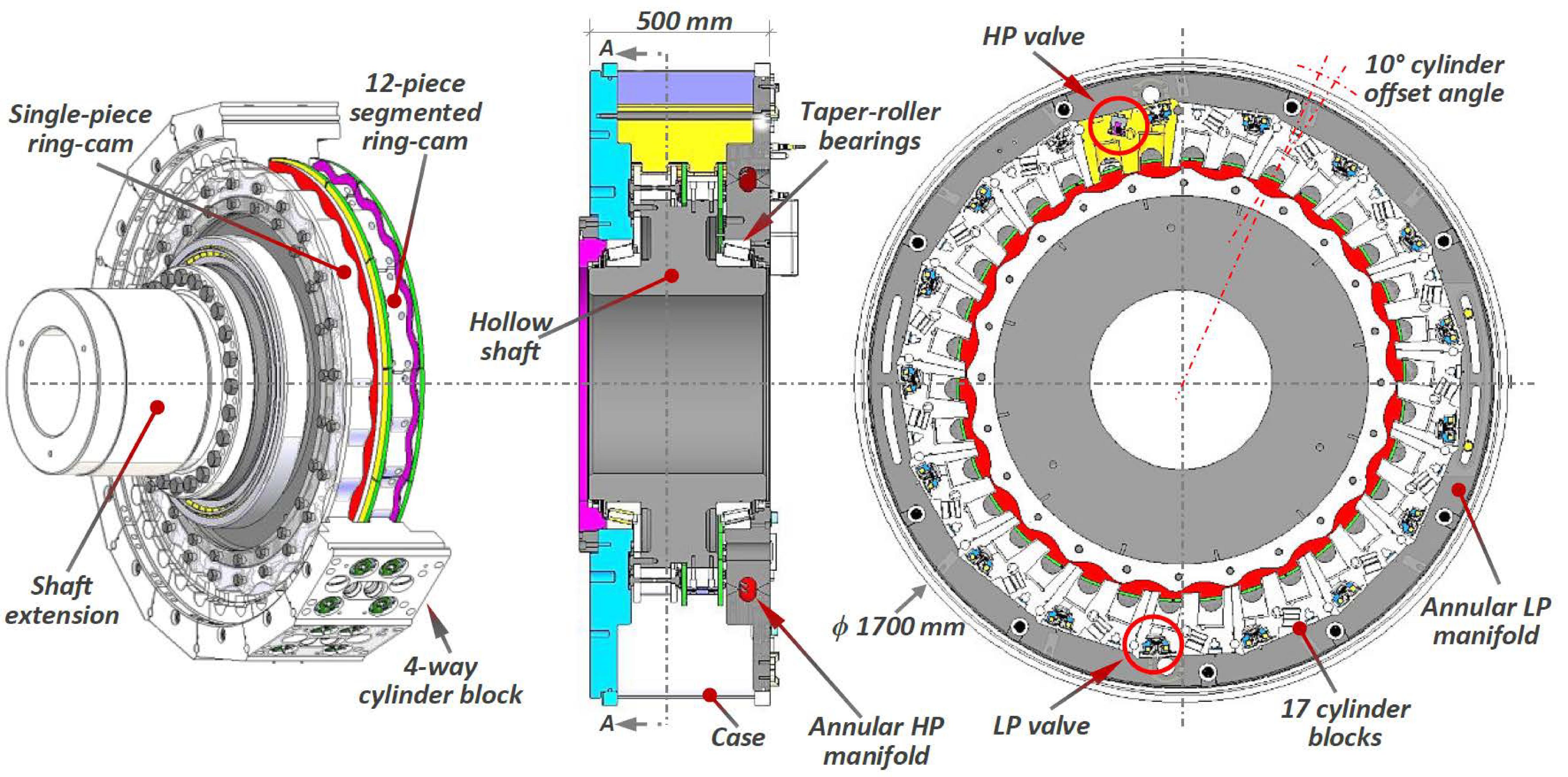
Figure 2 Radial and axial sectional drawings of the ‘R110’ ring-cam pump.
Table 1 Key details of the ‘R110’ ring-cam pump.
| Body length | 500 | mm |
| Body diameter | 1700 | mm |
| Shaft outside diameter | 620 | mm |
| Shaft inside diameter | 500 | mm |
| Rated rotational speed | 15 | min |
| Banks | 2 | |
| Cylinders per bank | 34 | |
| 4-way cylinder blocks | 17 | |
| Piston diameter | 75 | mm |
| Piston stroke | 25 | mm |
| Stroke offset angle | 10 | degree |
| Roller diameter | 56 | mm |
| Roller length | 84 | mm |
| Cam lobes per ring | 24 | |
| Cam segments per ring* | 12 | |
| Lobes per cam segment | 2 | |
| Cam nominal diameter | 1150 | mm |
| Lobe wavelength | 151 | mm |
| LP valve type | Active | |
| HP valve type | Passive | |
| Cylinder displacement | 110 | cc |
| Pump displacement | 179.5 | l/rev |
| Rated flow-rate | 44.9 | l/s |
| Rated flow-rate | 2.69 | m/min |
| Max. design pressure | 420 | bar |
| Max. operating pressure | 350 | bar |
| Boost pressure | 5 | bar |
| Case pressure | 0.5 | bar |
| Rated torque | 0.986 | MNm |
| Rated power | 1.55 | MW |
| *One of the two cam-rings is segmented. | ||
Like all ring-cam machines, the R110 was designed for high torque at relatively low rotational speeds though it has some special features that distinguish it:
• Electronically controlled variable displacement.
• Exceptionally high flow capacity.
• Outward-facing cam-rings that are attached to the shaft.
• One of the two cam-rings consists of multiple interlocking segments. This allowed performance comparison with a second, single-piece, cam-ring.
• Static inward-facing cylinders that form part of the structure.
The static cylinder layout is a requirement in any DD machine because the LP valves, which are mounted in the cylinder head, need to be electrically connected to the controller. However, this topology also allows the valves and fluid passages to be sized generously enough to significantly reduce the energy losses from excessive fluid pressure drops. This is not possible in conventional rotating cylinder machines where the flow-commutation arrangements and other fluid passages must be forced into the confined space near to the axis of the machine.
Design Considerations and Sizing
It had already been decided to base the pump design around the ‘CB’ piston that Hagglunds had developed for their well-proven ‘range of high-power, ring-cam motors. In this design the lower part of the piston wraps around a little over half of the circumference of the roller so that the sideways component of the cam-to-roller force, which provides the machine torque, reacts directly against the partially extended sides of the cylinder bore as the piston reciprocates within it. This arrangement is key to the very high power-to-size ratios of the Hagglunds machines.
The maximum torque of the DD ring-cam pump is proportional to the fluid displacement per shaft revolution. This is the product of cylinder displacement, number of cylinders and number of lobes on each cam-ring. Choosing the Hagglunds piston fixes the cylinder displacement, leaving only the number of cylinders and the number of cam-lobes as selectable parameters (Caldwell, 2018).
The circumferential spacing of cylinders is limited by the spatial interference of rollers with one another. The fixed piston stroke (from the Hagglunds piston) determines the amplitude of the cam lobes. The greater the number of lobes, the greater the slope in the cam surfaces and the higher the peak Hertzian stresses in the roller and cam surfaces. The magnitude of loading of the sliding interface between piston and cylinder also follows suit.
Iteration around these constraints led to a configuration of two side-by-side, 24-lobe, cam-rings with 34 cylinders acting on each one. These 68 cylinders provide a design torque capacity of very nearly 1 MNm at a maximum working pressure of 350 bar. The maximum input shaft-speed, which on a wind-turbine is determined by the rotor design, was fixed at 15 rpm and, neglecting losses, this set the nominal capacity of the transmission as 1.57 MW.
The ring-cam machine is a unidirectional pump, with no need for any motoring functionality, allowing some aspects of the design to take advantage of this ‘single-quadrant’ mode of operation. The axes of the cylinders are angled ten-degrees forward from the radial. This allows a useful component of the pump torque to be derived from the axial cylinder forces, reducing the piston side-loads and associated friction losses. To reduce the peak Hertzian stresses in the contact area of the cam, its profile is asymmetric between the unloaded ‘down-stroke’ zones where pistons draw in low-pressure fluid and the heavily loaded ‘up-stroke’ zones where pressurised fluid is delivered.
The sourcing of suitable steel-alloy material and an exacting sequence of processes that include forging, milling, heat-treatment, grinding, hardening and surface finishing, makes the manufacture of large cam-rings slow and expensive. It would be easier and cheaper if single-piece rings were replaced by multiple, identical, interlocking, cam-segments. These could be unbolted and replaced in-situ within the wind-turbine, unlocking the possibility of replacing all of the loaded hydraulic transmission components from within the nacelle and without the expense of heavy lifting operations at sea. In the single-quadrant DD pump, the parts of the cam-ring profile, where the pistons draw in low-pressure oil, provide lightly-loaded locations for interlocking joints between discrete segments. To allow performance comparison, one of the rings was made in this way as multiple segments with the other made by Schaeffler in Germany as a single-piece ring. MacTaggart Scott, a local Scottish manufacturer of ring-cam motors for naval use, provided Artemis with valuable guidance in the manufacture of the segmented cam pieces.
Figure 3 shows the R110 pump at an early stage of assembly. Its structure contains some design features that are particularly aimed at the modularity and serviceability referred to above. Seventeen segmented cylinder blocks are bolted radially between two end plates, to form a drum-like structure, with a hollow shaft passing through the centre. By removing any single cylinder block, access is gained to the inside of the pump, which in turn allows removal of the cam segments. By this means it is possible to change the cam, rollers and pistons without removing the machine from the wind-turbine.
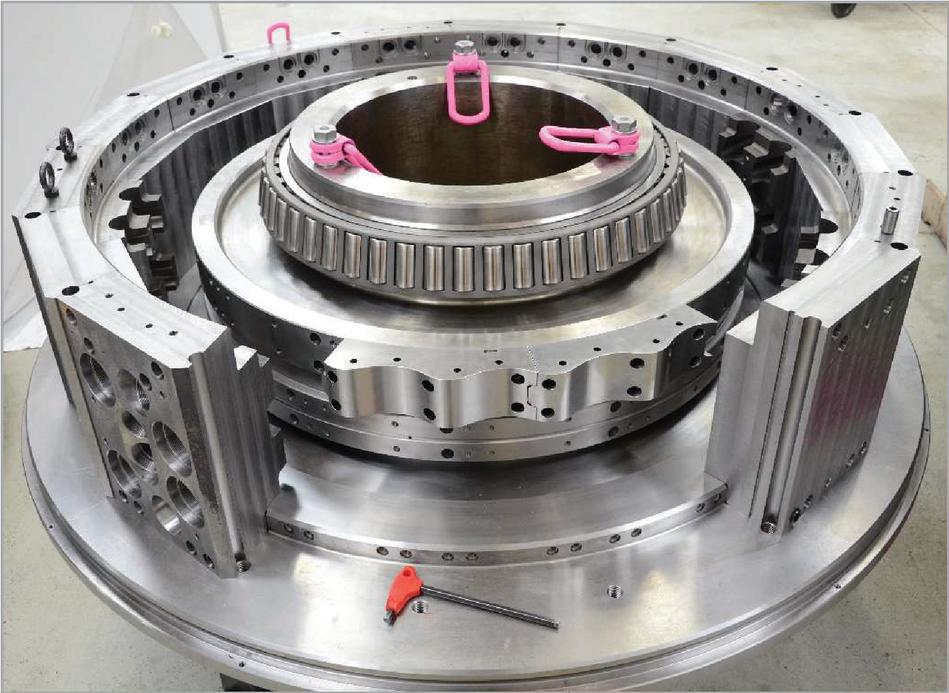
Figure 3 Trial assembly of R110 ring-cam pump components showing: the shaft; 14 of 17 cylinder-blocks (the one on the left is fully-machined) attached at their lower faces to one of two end-plates; one of two taper-roller bearings; two of 12 cam segments (with clearly visible joint detail). The second, single-piece, cam-ring is not yet fitted.
The low-pressure supply to the pump is provided by an annular plenum in the space around the cylinder block structure and inside the cylindrical steel tank that forms the outer boundary of the machine. With only two large O-rings on the outer diameters of the end-plates, this case also protects the wiring, valves and sensors. With the case pulled back, the valves are easily accessible and removable from the outward facing surfaces of the cylinder blocks.
The High-speed DD Motors
Fluid power from the R110 pump is converted to shaft power for the generators by two of the ‘Q40’ hydraulic motors shown in Figure 4, with some details listed in Table 2. These are four-bank radial-piston machines, with six 40 cc cylinders in each bank, so that each motor has a nominal geometric displacement of 960 cc per revolution. They were designed for rapid acceleration and fine speed modulation during generator synchronisation, followed by constant-speed operation at 1500 rpm (on 50 Hz networks).
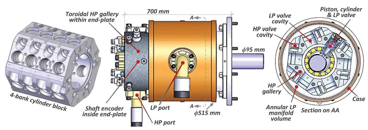
Figure 4 ‘Q40’ 24-cylinder DD motor, showing the single-piece cylinder block on the left and a single piston-cylinder assembly with its LP valve in the section view on the right.
The motor pistons run without piston-rings within close-fitting cylinders. At the bottom ends, the piston bearing-pads run directly on the crankshaft journals, supported by a combination of hydrostatic and hydrodynamic forces. The pistons are hollow with a controlled and tapered wall thickness that is designed to make them increase in diameter with pressure to minimise changes in the sliding piston-cylinder clearance, so that leakage at this interface is controlled.
As the bearing pads follow the crankshaft, the cylinders accommodate the changing piston angles by swivelling at the top end by up to 7 degrees fore and aft of the centre position. This freedom is provided by hydrostatically over-clamped bearings formed between the spherical outer ends of the cylinders and matching spherical sockets in the inner part of the LP valve assemblies. This articulation virtually eliminates side forces between pistons and cylinders and is a common feature in radial machines manufactured by Parker-Calzoni and by Bosch-Rexroth. It has the benefit of being kinematically correct, in that all internal deflections, due to pressurisation and loading, can be accommodated without generating point or line contact on the highly loaded, high-velocity, piston-pad surface. The energy losses in the piston-cylinder interface and in the spherical top-end articulation are small compared with those of the piston-pad bearing, largely because the sliding velocities are low. Poor design of the piston-pad bearing can cause high losses and lead to rapid failure of the machine.
Table 2 Key details of the ‘Q40’ motors. The ‘motoring down-rate factor’ is due to the early closing of LP valves before top-dead-centre to equalise the pressure-drops across HP valves so that the relatively modest solenoid forces can then open them.
| Body length | 700 | mm |
| Body diameter | 515 | mm |
| Shaft diameter | 95 | mm |
| Rated rotational speed | 1500 | min |
| Banks | 4 | |
| Cylinders per bank | 6 | |
| Piston diameter | 40 | mm |
| Piston stroke | 32 | mm |
| LP valve type | Active | |
| HP valve type | Active | |
| Cylinder displacement | 40 | cc |
| Total displacement | 960 | cc/rev |
| Motoring down-rate factor | 0.9 | |
| Max. motoring displacement | 864 | cc/rev |
| Rated flow | 21.6 | l/s |
| Max. design pressure | 420 | bar |
| Max. operating pressure | 350 | bar |
| Case & boost pressure | 5 | bar |
| Rated torque | 4.74 | kNm |
| Rated power | 745 | kW |
The piston and cylinder pairs are energised by coaxial coil-springs that push the ends of the assembly into contact respectively with the camshaft and the spherical sockets at the inner end of the LP valve assemblies. The spring forces vary during the stroke, effectively counteracting the radial acceleration forces on the piston, so that the pads stay in contact with the crankshaft journal.
Fluid commutation into and out of each cylinder is through the high-speed solenoid-actuated poppets of the LP and HP valves. The normally-open LP valves screw into the cylinder body, collinear with the cylinders, communicating directly with the LP manifold formed by the annular plenum between the cylinder block and the motor case. In all pumping and motoring states, whatever the current net displacement of the machine, the LP valves are open during every intake stroke. To minimise flow losses, they are therefore larger in diameter than the HP valves. As the HP valves are open only when a cylinder is active and, because they are usually supplied with high pressure fluid, pressure drop and cavitation considerations are relatively less important than for the LP valves.
The design of solenoid-actuated valves is integral to the successful and reliable operation of DD machines. To achieve the smoothest and quietest possible operation under changing speed, pressure and temperature, their switching times and performance must be consistent and controllable. Successful design requires practical and analytic understanding of mechanical stresses, magnetic fluxes, complex flow passages and dynamic effects.
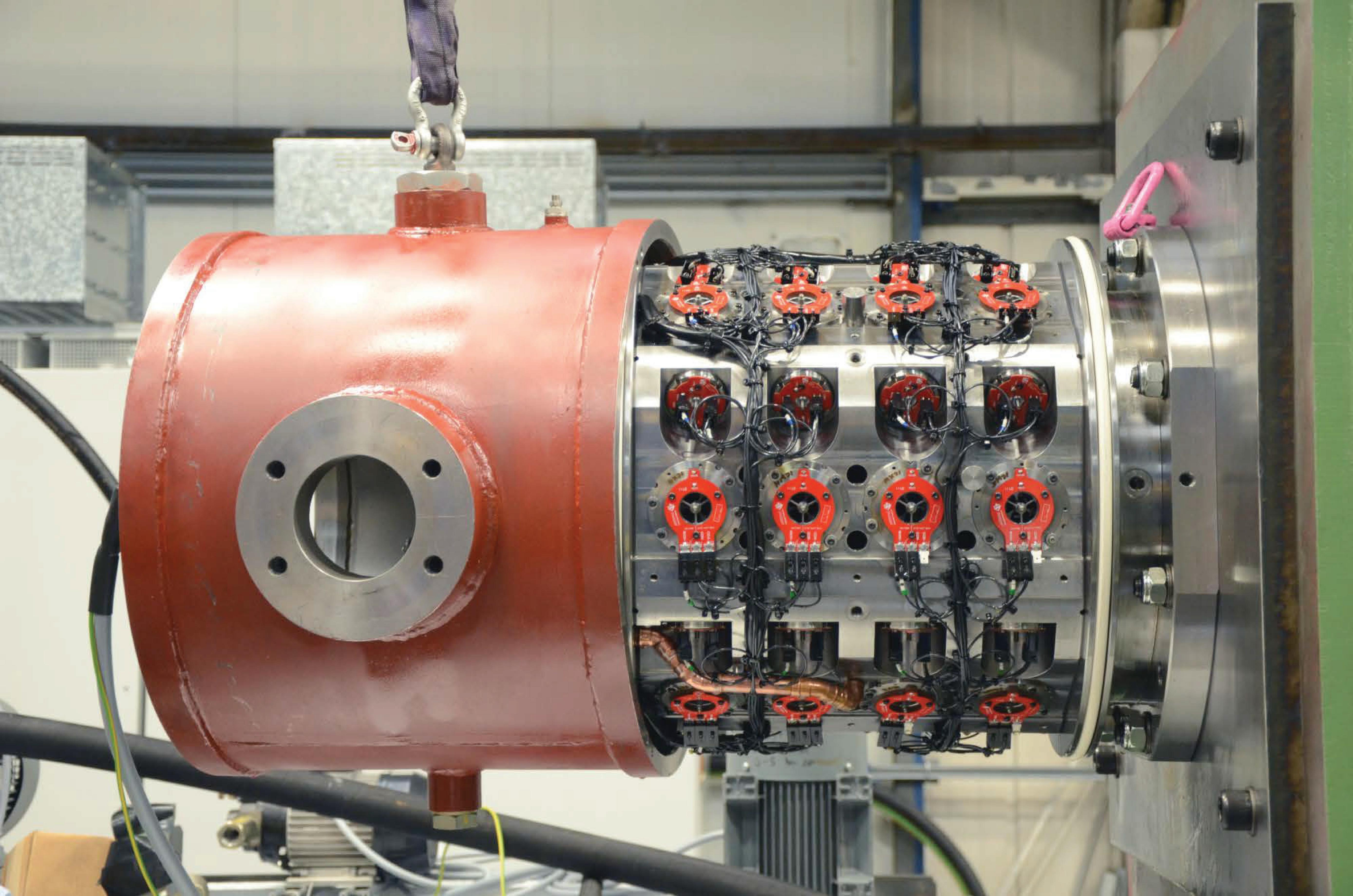
Figure 5 One of the two ‘Q40’ motors with its case pulled back, showing the solenoid-activated LP and HP valves. The welded cylindrical appendage on the side of the case accommodates a flanged connector for the LP return flow.
The low-pressure plenum volume between the case and the cylinder block provides a large flow area for the cylinders to breathe easily through their LP valves, with minimal fluid inertia effects. High-pressure oil is transmitted to the HP valves from a toroidal gallery within the endplate and through long axial drill-ways in the machine body. Figure 5 shows one of the motors during installation on the test-rig, with its case open and valve electrical connections visible.
At a critical point in each revolution of the crankshaft, the motor’s embedded controller determines whether a particular cylinder should remain idle or whether it is needed for a motoring stroke. This decision is taken independently for each cylinder in the machine without reference to the past enabling history. Unlike conventional machines, the DD motor can therefore vary its displacement and torque with no hysteresis. As with the DD pump, during the up and the down piston strokes of an idling cycle, fluid is simply drawn from and returned to the annular LP manifold through open LP valves and with very little parasitic energy loss.
An active motoring cycle in a DD motor is more complicated than an active pumping cycle in a DD pump. When an enabling decision has been made, the motoring cycle begins before the piston reaches top-dead-centre with the early closing of the LP valve on the cylinder exhaust stroke. This last fraction of the up-stroke raises the in-cylinder pressure until it matches that on the supply side of the HP valve, allowing the valve to open and then be kept open by the relatively small force from the HP solenoid. As the piston passes top-dead-centre, pressurised fluid flows in and pushes the piston down, supplying torque to the crankshaft. At the end of the motor stroke, as the piston approaches bottom-dead-centre, the HP valve solenoid is switched off and the HP valve returns to its normally-closed position. The fluid pressure in the cylinder then drops until the cycle completes with the passive re-opening of the LP valve. The ensuing upstroke discharges the fluid back to the low-pressure plenum.
Motoring strokes are very efficient, because the mechanics of the machine are designed to minimise losses and because HP valves switch state only when there are small pressure differences across them. The energy stored during the compression phase, due to the fluid bulk modulus, is therefore recovered during the decompression phase of the cycle.
Transmission Test-rig
The dynamometer test-rig, shown in general arrangement in Figure 6, was built to evaluate and characterise the transmission. It provided a low-speed drive to the DD ring-cam pump, electrical machines to load the DD motors and comprehensive instrumentation to provide accurate measurements of the key parameters.
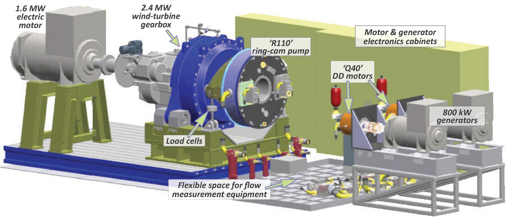
Figure 6 Outline arrangement of test-rig components. The variable-frequency ‘inverter’ control electronics allow the two 800 kW induction motors on the right to be configured as if synchronous generators. The hydraulic connections between machines are not shown.
The low-speed drive was by a 1.6 MW four-pole electric induction-motor through a reverse-driven, 2.4 MW, three-stage wind-turbine gearbox with an overall speed reduction ratio of 90.6 to 1. The low-speed shaft of the gearbox was coupled to the ring-cam pump shaft by a shrink-disc coupling. The 1.6 MW motor was driven by a Control Techniques ‘UniDrive’ variable-frequency inverter, such that the ring-cam pump could be operated over a speed range from zero to 20 rpm.
Each DD motor was loaded by an 800 kW four-pole induction machine on its own UniDrive inverter within the Control Techniques system. The electric machines were used to drive the Q40 DD motors in pumping-mode during commissioning and were then re-configured to mimic fixed-speed, 1500 rpm, synchronous generators during full system testing. All three inverter drives shared the same ‘DC bus’ so that electrical power generated by the test-rig could be recirculated back to the input, reducing the energy costs of running the test-rig.
Table 3 gives some details of sensors that were used for mechanical and fluid power calculations during the testing of the transmission. The torques and speeds of the DD pump and of the DD motors were required for shaft-to-shaft efficiency calculations. The torque reaction of the DD pump body was taken via a bolted-on torque plate whose arms were coupled to the test-rig frame through a pair of counter-tensioned PCM load-cells. A very accurate speed signal was obtained by timing the pulses from a Sick high-resolution shaft-encoder on the low-speed shaft of the gearbox. The torques and speeds of the DD motors were taken from HBM non-contact sensors, mounted in-line with the couplings to their respective electrical machines.
Table 3 Sensors used on the test-rig for energy and power calculations. Only the first ‘mechanical’ group of sensors were used for the steady-state efficiency results shown in the next section.
| Function | Make | Type | Comment | Accuracy |
| Mechanical | ||||
| DD ring-cam pump, torque | PCM | TC4 | Bi-directional pancake load cell | 0.05% |
| DD ring-cam pump, speed | Sick | DFS60B | Incremental encoder, 10 pulses/rev. | |
| DD motor, torque & speed | HBM | T40 | ‘Non-contact, rotating. | 0.1% |
| Fluid | ||||
| HP flow-rate | KEM | HM | Fast-response, turbine flow-meters (2 off) | 1.065%, 1.194% |
| HP pressure | HBM | P3ICP | High-accuracy (3 off) | 0.027, 0.028, 0.027% |
| LP pressure | Wika | S-10 | 0.2% | |
Fluid flow-rates and differential pressures were required for fluid power calculations. The pump’s high-pressure fluid output passed, via large diameter hoses, through parallel instrumentation blocks containing KEM turbine flow-meters and thence to the motors. The low- and high-pressure ports of both the pump and of the two motors were fitted with accurate pressure transducers, allowing for differential pressure to be used in power calculations and for the pressure drops incurred in the passage through the flowmeters to be accounted for. Pressure relief valves were installed on the pump and motor HP manifolds.
Two ten-litre HP bladder-type accumulators were fitted to the pump and one to each of the motors, all of which were pre-charged to 120 bar, giving a total accumulator volume of 40 litres. To provide additional compliance and energy storage, a high capacity HP accumulator block, was also installed on the test-rig. This comprised two piston accumulators, respectively with 50 and 65 litre capacities, and both pre-charged to 180 bar. These could be selectively connected to the hydraulic circuit, to provide 50, 65 or 115 litres of additional HP accumulator volume. They were not used during the steady-state efficiency testing described in the following section but were an important part of later work in the development of the transmission control system.
The LP outlets of the Q40 motors were maintained at a low 5 bar boost pressure, sufficient for the return flow to be passed through a filter and cooler before being returned to the ring-cam pump with no risk of cavitation. Drain lines returned leakage flows from the three DD machines to the atmospheric-pressure tank. An off-line filtration system was used to continuously condition the oil in the unpressurised tank and a small boost pump fed some of this back to the low-pressure line to make up the drain leakage flows.
A Dewesoft ‘DS-NET’ data acquisition system recorded test data at 5 kHz, synchronising analogue and digital data with control signals from CAN bus signals to and from the low-level embedded pump and motor controllers. Figure 7 shows the completed system as it appeared during commissioning and testing.
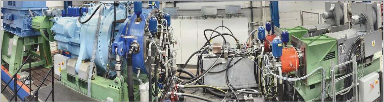
Figure 7 Panoramic view of the test-rig as built. Just right of centre is the (grey) backup oil reservoir. Partially out of sight in front of it are the two high-accuracy flow-meters.
Steady-State Testing
The transmission was tested across a range of steady-state conditions, typical of those within a ‘reference’ 1.5 MW wind-turbine, with its control parameters set to maximise the electricity generated at each ‘windspeed’. In these tests, the DD pump was driven via the speed-reduction gearbox by the 1.6 MW electric motor with closed-loop control of its variable-speed drive such as to emulate a wind-driven rotor. Anderson, 2020, discusses the general issue of optimal wind rotor loading and, for this case, the torque loading provided by the DD ring-cam pump is illustrated by the two plots of Figure 8.

Figure 8 The wind-rotor and transmission loading characteristics. Left: ‘Cp-’ (power coefficient against tip-speed ratio) curve for the reference 100 m diameter rotor. Right: The corresponding transmission torque and power curves plotted against rotor speed.
The left-hand plot in Figure 8 is a ‘Cp-lambda’ curve from an aerodynamic model of a 100 m diameter rotor whose three rotor blades are at the ‘zero-angle’ pitch position used for maximum aerodynamic efficiency in low and moderate wind-speeds. Cp, the dimensionless ‘power coefficient’, expresses the efficiency with which the rotor extracts energy from air passing through the swept area. This varies according to how its speed is constrained by the reaction torque applied by the transmission. Lambda, , is the non-dimensional ‘tip speed ratio’, the circumferential speed of the tips of the rotor blades divided by the freestream wind-speed. For the unducted rotors used in virtually all wind-turbines the theoretical maximum, ‘Betz limit’, Cp value is just over 0.59. For the rotor design of Figure 8, the peak Cp value of 0.492, is typical of currently achievable values. The relatively high tip-speed ratio of 9.3 at which this occurs indicates a slender-bladed, low-solidity rotor.
The right-hand plot of Figure 8 shows how, with the rotor loaded so as to maintain the peak Cp value after cutting in at 4 rpm, the torque and power increase respectively with the square and cube of speed. The step-increases at 15 rpm, as rated power is achieved, correspond to the onset of blade feathering or pitching to deliberately reduce the aerodynamic efficiency. The rotor speed then continues to increase with wind-speed up to around 25 or 30 ms at which point, to reduce stresses, the wind-turbine would be shut down and rotor parking brakes applied.
The steady-state test results are summarised in Table 4. At each shaft-speed, the pump torque follows the rotor model shown on the right of Figure 8. Fractional displacement commands, Fd, to the pump were calculated according to these target torque values and to the prevailing system pressure.
The secondary control variable, system pressure, was implemented via the Fd commands to the DD motors (the same Fd value was used for both motors) which ran at a fixed 1500 rpm speed. To minimise leakage and bearing losses, and maximise transmission efficiency, pressure increased proportionally with power up to a nominal maximum of 350 Bar.
Table 4 DD transmission, steady-state test results with shaft-to-shaft efficiencies.
| Pump | Pump | Input | Pump | Fractional displacement | Output | Transmission | |
| speed | torque | power | pressure | DD pump | DD motors | power | efficiency |
| rpm | kNm | kW | bar | Fd | Fd | kW | % |
| 5 | 106 | 55 | 173 | 0.21 | 0.07 | 23 | 41 |
| 6 | 146 | 92 | 177 | 0.28 | 0.12 | 58 | 63 |
| 7 | 199 | 146 | 183 | 0.37 | 0.18 | 109 | 75 |
| 8 | 256 | 215 | 192 | 0.46 | 0.26 | 173 | 81 |
| 9 | 327 | 308 | 203 | 0.56 | 0.34 | 263 | 85 |
| 10 | 404 | 424 | 217 | 0.65 | 0.46 | 372 | 88 |
| 11 | 486 | 561 | 233 | 0.73 | 0.57 | 501 | 89 |
| 12 | 578 | 726 | 253 | 0.80 | 0.68 | 655 | 90 |
| 13 | 673 | 917 | 275 | 0.86 | 0.80 | 833 | 91 |
| 14 | 784 | 1150 | 302 | 0.91 | 0.91 | 1048 | 91 |
| 15 | 911 | 1425 | 341 | 0.93 | 1.00 | 1295 | 91 |
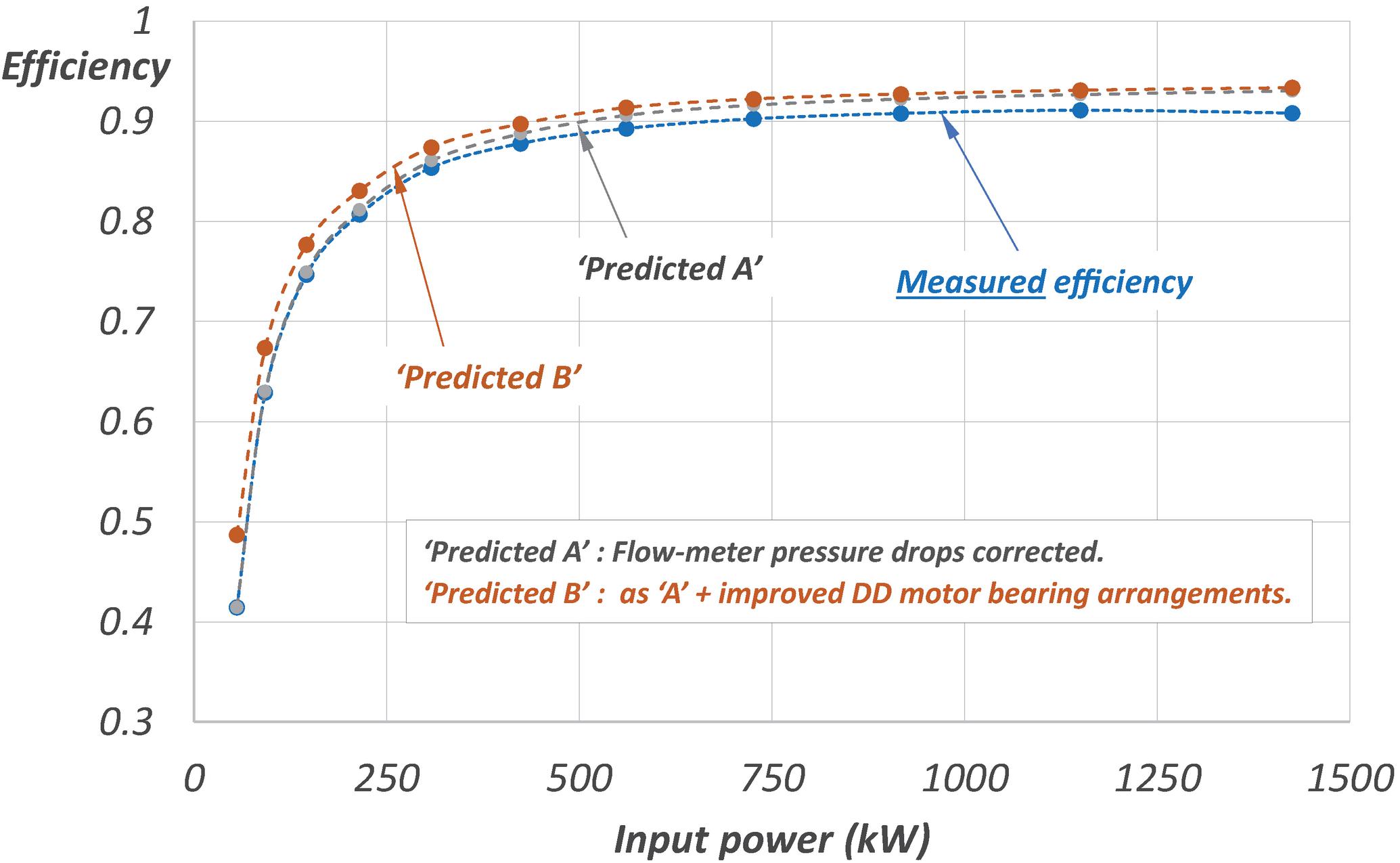
Figure 9 Steady-state, DD transmission shaft-to-shaft efficiency against power. Measured values from Table 1 are shown in the lowest curve. Two additional data sets show improvements if lab-specific losses are discounted and with improved motor bearing lubrication.
Note that the power and shaft-to-shaft efficiency values in Table 4 are based only on measured speed and torque values, avoiding the relative difficulty of making accurate flow measurements. The overall efficiency of the test transmission peaked at 91% at the point of highest input power (1.425 MW) but two considerations suggest that this value was conservative with respect to potential future commercial versions of the DD wind-transmission.
• Pressure drops in the hydraulic circuit incurred by the insertion of high accuracy flow-meters were not accounted for. These would not be present in a production turbine transmission. If they are discounted, a peak efficiency of 93% would be achieved at peak power.
• The shaft bearings used in the DD motors were fully-flooded. In production machines they would be drained, reducing the power loss by 4 kW under all operating conditions. This reduction was initially predicted by SKF’s rolling-element bearing calculator (SKF, 2021) and confirmed in separate lab tests.
The transmission efficiency values of Table 4 are plotted in Figure 9 with additional curves to represent the predicted performance with an optimised hydraulic circuit (no flow measurement block) and with improved bearing arrangements in the DD motors.
Summary and Conclusions
A 1.5 MW hydrostatic wind-turbine transmission using a Digital Displacement® (DD) ring-cam pump and two DD generator drive-motors was designed and built. The complete system was tested on a purpose-built dynamometer test-rig. Power losses and net transmission efficiencies were obtained from steady-state tests across the full power range with the input shaft speed varying in the same relationship as would occur in a wind-turbine and with the generators driven at a constant 1500 rpm speed.
Shaft-to-shaft efficiency at full power peaked at 91% in the lab, with a flow metering manifold in the hydraulic circuit, and was predicted to reach 93% in an operational system. At a part-load of 25%, the corresponding efficiencies were 86% and 88% respectively. By turning off one of the two motors when operating below 50% rated power, the rotating losses of one idling Q40 motor could be discounted, raising the efficiency to above 90% at the 25% power level.
The objective of demonstrating a high-power hydrostatic transmission for a wind-turbine, which could provide a controllable and efficient interface between a variable-speed rotor and constant-speed synchronous generators, was achieved.
Following the technical success of the transmission, two much larger 7 MW variants were built and operated by Mitsubishi Heavy Industries (Sasaki et al., 2014). The present authors intend to publish further papers describing systematic experimental testing of the 1.5 MW transmission to establish verified DD machine loss-models and on the control of the 7 MW transmission.
Funding
This work was supported by The Carbon Trust under Grant 062-181; and The Department of Energy and Climate Change under the ETF Offshore Wind Demonstration Call.
References
Anderson, C.G. 2020. Wind turbines: Theory and practice, Cambridge University Press.
Caldwell, N. 2018. Review of Early Work on Digital Displacement Hydrostatic Transmission Systems, Bath/ASME 2018 Symposium on Fluid Power and Motion Control, Bath. https://doi.org/10.1115/FPMC2018-8922
Ehsan, M.D., Rampen, W.H.S. and Salter, S.H. 2000. Modelling of Digital-Displacement Pump-Motors and Their Application as Hydraulic Drives for Nonuniform Loads, Journal of Dynamic Systems, Measurement, and Control, vol. 122, pp. 210–215. https://doi.org/10.1115/1.482444
Freris, L. and Infield, D. 2008. Renewable Energy in Power Systems, Wiley.
Lawson-Tancred, H. 1984. Generating Electricity, UK Patent GB2125486.
Lindholdt, P.N., Gregersen, K., Herbsleb, E., Hoejsgaard, H.H., Joergensen, A.H., Koldkjaer, P., and Nielsen, C.M. 2014. Hydraulic transmission methods and apparatus for wind turbines, Europe Patent EP2668398.
Rampen, W.H.S. 1992. Digital Displacement Hydraulic Piston Pump, PhD thesis, The University of Edinburgh. https://era.ed.ac.uk/handle/1842/12829
Rampen, W., Riddoch, F. and Taylor, J.R.M. 2006. Gearless Transmissions for Large Wind Turbines, DEWEK – Conference of the German Wind Energy Association, Bremen. http://www.artemisip.com/wp-content/uploads/2016/03/2006-11-Gearless-Transmissions-Bremen.pdf
Rybak, S.C. 1982. Description of the 3 MW SWT-3 wind turbine at San Gorgonio Pass, California. NASA, Lewis Research Center Large Horizontal-Axis Wind Turbines, pp. 575–588. https://ui.adsabs.harvard.edu/abs/1982lhaw.rept..575R/abstract
Salter, S.H. 1984. Hydraulics for Wind, European Wind Energy Conference, Hamburg. http://www.artemisip.com/wp-content/uploads/2017/11/1984-Salter-Hydraulics-for-Wind-3_0.pdf.
Sasaki, M., Yuge, A., Hayashi, T., Nishino, H., Uchida, M. and Noguchi, T. 2014. Large Capacity Hydrostatic Transmission with Variable Displacement, 9th International Fluid Power Conference, Aachen, Germany. http://www.artemisip.com/wp-content/uploads/2016/03/2014-03-24to26-9th-IFK-Aaacehn-MHI-DDT.pdf
Say, M.G. 1983. Alternating Current Machines, Pitman.
SKF, 2021, Bearing friction, power loss and starting torque, https://www.skf.com/uk/products/rolling-bearings/principles-of-rolling-bearing-selection/bearing-selection-process/operating-temperature-and-speed/bearing-friction-power-loss-and-starting-torque on 2021-01-15 17:32 GMT
Smith, A.Z.P. 2020. UK offshore wind capacity factors. Retrieved from https://energynumbers.info/uk-offshore-wind-capacity-factors on 2021-01-11 19:02 GMT
Thomsen, K.E., Dahlhaug, O.G., Niss, M.O.K. and Haugset, S.K. 2012. Technological Advances in Hydraulic Drive Trains for Wind, Energy Procedia, vol 24, pp. 76-82. https://www.researchgate.net/publication/257712258_Technological_Advances_in_Hydraulic_Drive_Trains_for_Wind_Turbines
Biographies

Win Rampen, FReng, developed Digital Displacement hydraulics, initially intended for wave energy devices, in Stephen Salter’s research group at The University of Edinburgh. In 1994 he co-founded Artemis Intelligent Power to further refine and commercialise the technology. He was Managing Director until 2013, remaining as Chairman of Artemis until 2019. In 2014, he re-joined the University, working in both fluid power and thermal energy storage.

Daniil Dumnov holds a BE(hons) in Engineering Science from the University of Auckland and has worked for 15 years at Artemis, leading the Systems and Simulation team. Daniil has led the development and testing of control systems for hydraulic hybrid vehicles and wind-turbine transmissions using Digital Displacement technology.

Jamie Taylor, trained as an electrical and electronic engineer and started his engineering career in the 1970s at the University of Edinburgh, working on Stephen Salter’s pioneering ‘Duck’ wave-energy device. From 2007, as Senior Project Manager at Artemis he was responsible for the wind-turbine transmission as well as for hybrid rail, bus and wave-energy systems.

Henry Dodson worked at Artemis from 2010 to 2018, as a mechanical design engineer in the development of Digital Displacement technology. With an interest in tribology, he increasingly specialised in the design of ‘rotating groups’. Whilst at Artemis, he wrote his University of Edinburgh PhD thesis on the ‘Design of a Digital Displacement Pump Piston for Multi-Megawatt Offshore Wind Turbine Transmissions’.

John Hutcheson is currently pursuing a PhD in ‘efficient Digital Displacement hydraulic systems’ at The University of Edinburgh whilst also working as a research and development engineer for Artemis. John’s main research interest is in the development of novel energy saving hydraulic systems for off-highway machines.

Niall Caldwell Managing Director of Artemis since 2013, directed the electronics, modelling and control teams during the development of the 1.5 and 7MW wind turbine transmissions. Niall joined Artemis in 1999 and developed the first Digital Displacement motors and built the initial DD vehicle transmissions.
International Journal of Fluid Power, Vol. 21_1, 87–112.
doi: 10.13052/ijfp1439-9776.2213
© 2021 River Publishers