Open-loop Independent Metering Control of a Multi-DOF Forwarder Boom
Mikko Huova*, Jyrki Tammisto and Matti Linjama
Automation Technology and Mechanical Engineering, Tampere University, Korkeakoulunkatu 6, FI-33720, Tampere, Finland
E-mail: mikko.huova@tuni.fi; jyrki.tammisto@tuni.fi; matti.linjama@tuni.fi
*Corresponding Author
Received 15 January 2020; Accepted 19 August 2020; Publication 05 November 2020
Abstract
This study applies independent metering control in a forestry forwarder in order to improve its energy efficiency. The paper describes the control method, which enables smooth control mode switches and relatively accurate velocity tracking without position, velocity or acceleration feedback. The energy saving capability is analysed through measured, realistic, working cycle, which is repeated for the baseline system and independent metering system. The input energy taken by the control valves is compared. Furthermore, the power losses of the supply pump and diesel engine are modelled to achieve semi-empirical estimate for the diesel fuel consumption. The results show an average reduction of 25% in the fuel consumption when compared to the baseline.
Keywords: independent metering; forwarder; energy saving.
Introduction
The reduction of energy losses in hydraulic mobile machines is an important task as the machines are used extensively and typically powered by diesel engines. Independent metering control is one approach to decrease the throttling losses in the working actions of mobile machines [Jansson 1990]. The independent metering, sometimes called separate meter-in separate meter-out control (SMISMO), decouples the control edges, which throttle the inflow and outflow of a double-acting cylinder (or hydraulic motor). The independent metering concept allows elimination of unnecessary pressure losses while simultaneously avoiding cavitation and retaining hydraulic springs on both cylinder chambers.
There are two main valve configurations utilized in independent metering control. When 3/3 type proportional directional control valves are used, two separately controlled spools are required per actuator. Such configurations are studied for example in [Elfving 1997], [Mattila 2000], [Yuan 2005], [Hansen 2011], [Koivumäki 2013], [Ge 2015]. The valve configuration enables the reduction of unnecessary pressure losses and is therefore capable of increasing the energy efficiency to certain degree.
When applying independent metering, double-acting cylinders can be driven using different control modes, such as inflow-outflow control mode (powered extension) or differential control mode (high-side regeneration mode) as presented in Figure 1. Similarly, a retracting movement can be performed in inflow-outflow or differential control mode. However, by using just two 3/3 type control valves, a controlled transition from control mode to another without a significant disturbance in velocity tracking is difficult. Lately, there has been some effort to mitigate the transients during mode switching with this particular valve configuration [Ding 2016].
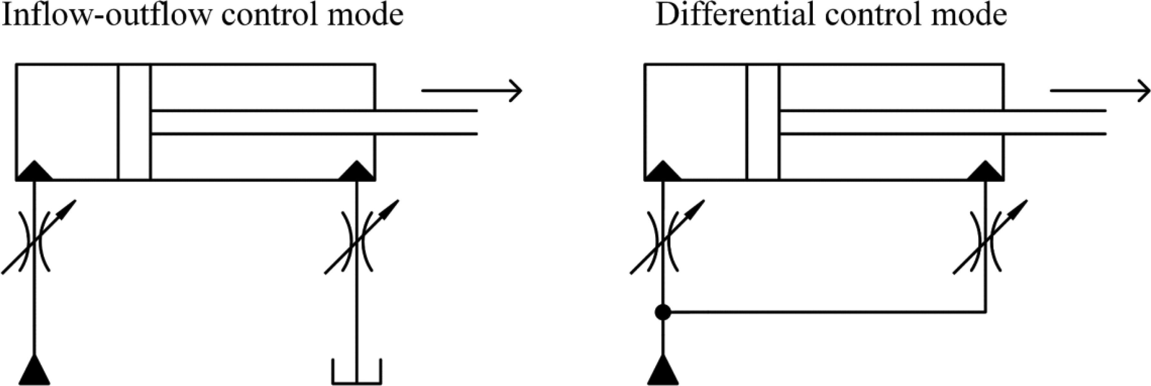
Figure 1 Different control modes for extending piston movement.
In single actuator systems, a single control mode is sufficient, when load sensing supply pressure is used. However, in multiactuator systems, only the actuator of highest load pressure receives the optimal supply pressure. In terms of energy efficient multi-actuator control, the ability to switch from one control mode to another is crucial in many applications. Figure 2 presents an example of the difference in throttling losses, if the system uses inflow-outflow control mode only, or if both control modes are used, where appropriate. In this example, cylinder areas are 0.01 m and 0.005 m, maximum pressure is 20 MPa, minimum acceptable pressure difference () across an active control edge is 1.5 MPa and supply pressure is 18 MPa.
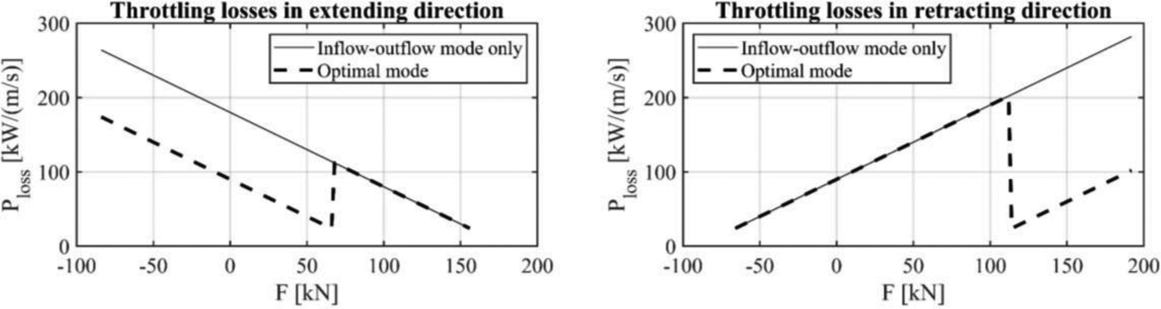
Figure 2 Throttling losses as a function of cylinder load force.
The second valve configuration often utilized in independent metering control consist of four (or five) 2/2 type proportional control valves. Such valve configurations have been studied for example in [Jansson 1990], [Eriksson 2008], [Eriksson 2009], [Eriksson 2010], [Yao 2002], [Hu 2002]. When each flow path is independently controllable, transient free control mode switching becomes possible. The control modes utilized in this paper are presented in Figure 3.
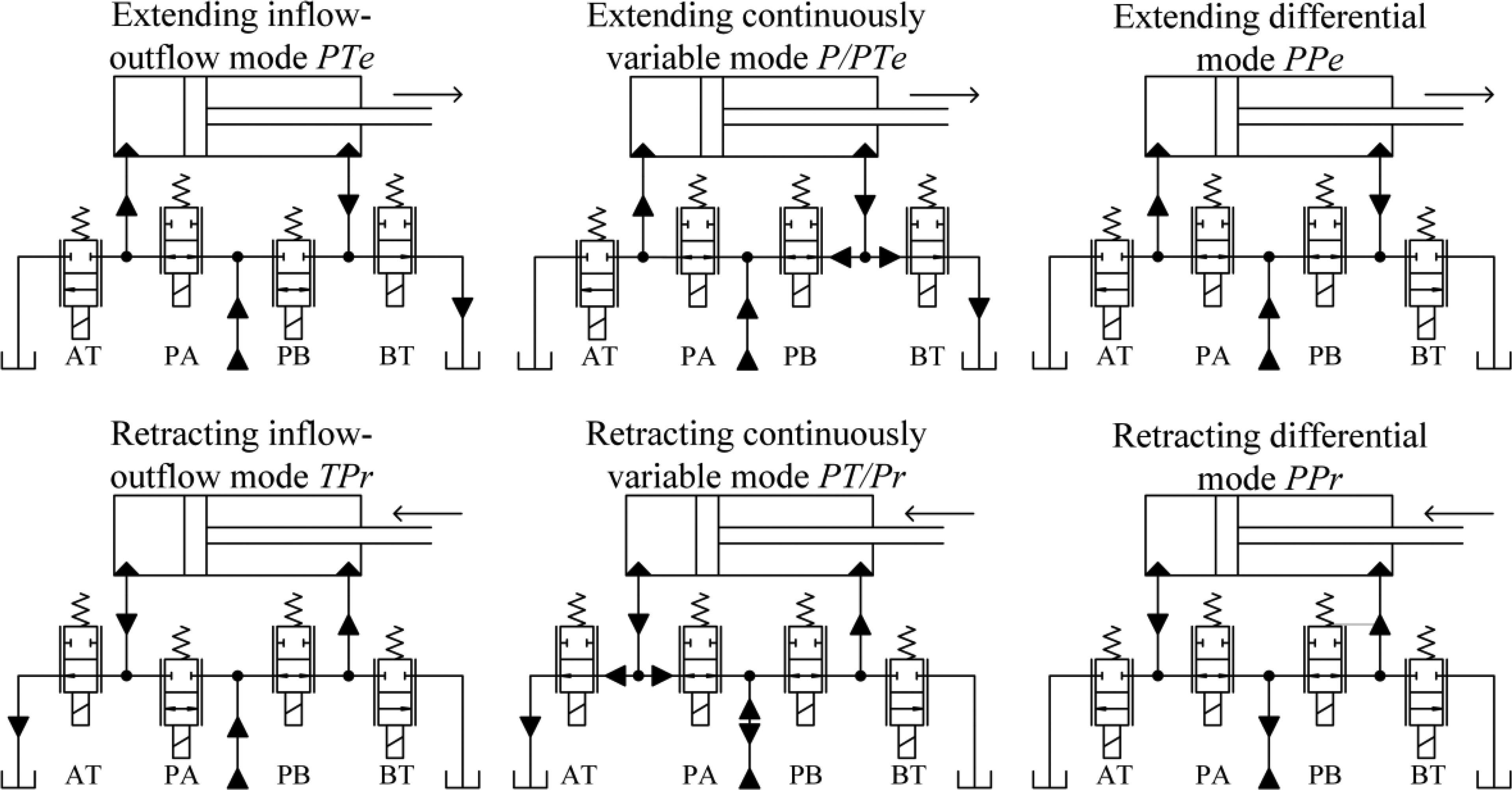
Figure 3 Control modes of a four-valve independent metering system. Control modes where tank line is connected to inflow-side of the cylinder are not utilized in this paper and are thus omitted.
The transition phase between inflow-outflow control mode and differential control mode can be handled by using a so-called continuously variable modes (CVM), which are introduced in [Shenouda 2006]. Three valves are simultaneously controlled in these modes to gradually switch from one control mode to another.
Previously, the independent metering control has been studied for example in wheel loaders [Eriksson 2010]. Furthermore, a numerical study of the energy efficiency of independent metering-controlled wheel loader is presented in [Huova 2018]. Yao applies the independent metering in control of robotic arm in [Yao 2002]. Eriksson has studied independent metering control also in forestry forwarders [Eriksson 2008] and [Eriksson 2009]. However, in these papers only a single actuator in the crane is modified for independent metering.
This paper presents a control mode selection logic based on simultaneous tracking of chamber pressures and piston velocity. The target of the control mode selection logic is to achieve accurate and seamless velocity tracking despite varying control modes. The control system is experimentally tested in a multi-actuator forestry forwarder crane presented in Figure 4. A realistic work cycle including loading and unloading of logs is measured. The experiment is carried out with the baseline system and with the independent metering system in order to evaluate the hydraulic energy losses. Furthermore, an efficiency map of the supply pump and diesel engine are used to estimate the effect on diesel fuel consumption.
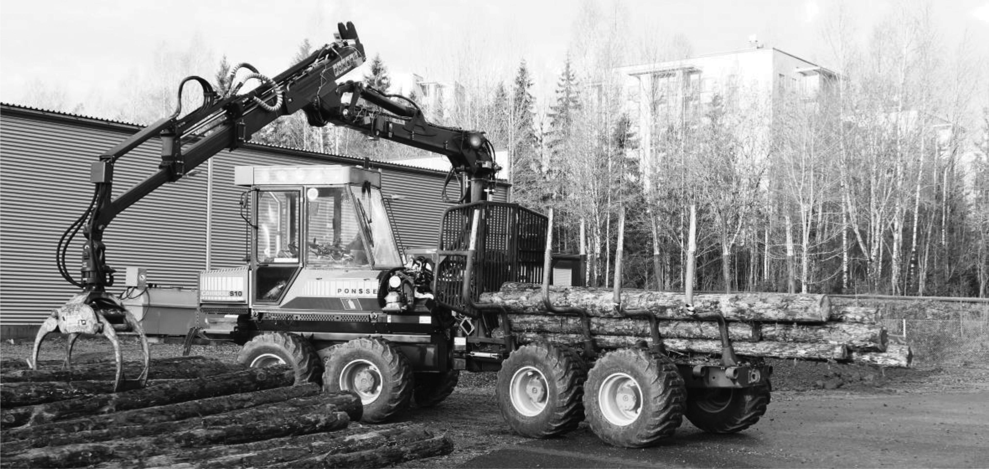
Figure 4 Ponsse Caribou – forwarder at the test site.
Control Methods
In this paper, the basis of the independent metering control is to use chamber pressure measurements and a steady-state valve model to achieve velocity tracking control without position, velocity or acceleration feedback. As such, the control scheme is well suited for a human operator, who controls the actuator velocities through joystick commands.
Control architecture
The control architecture of the multi-DOF independent metering valve controller is presented in Figure 5. The actuator controller is responsible for setting the control mode and giving the valve controllers the inflow- and outflow-side pressure references and flow rate references . The load sensing supply pressure reference is generated by the actuator controller as well.
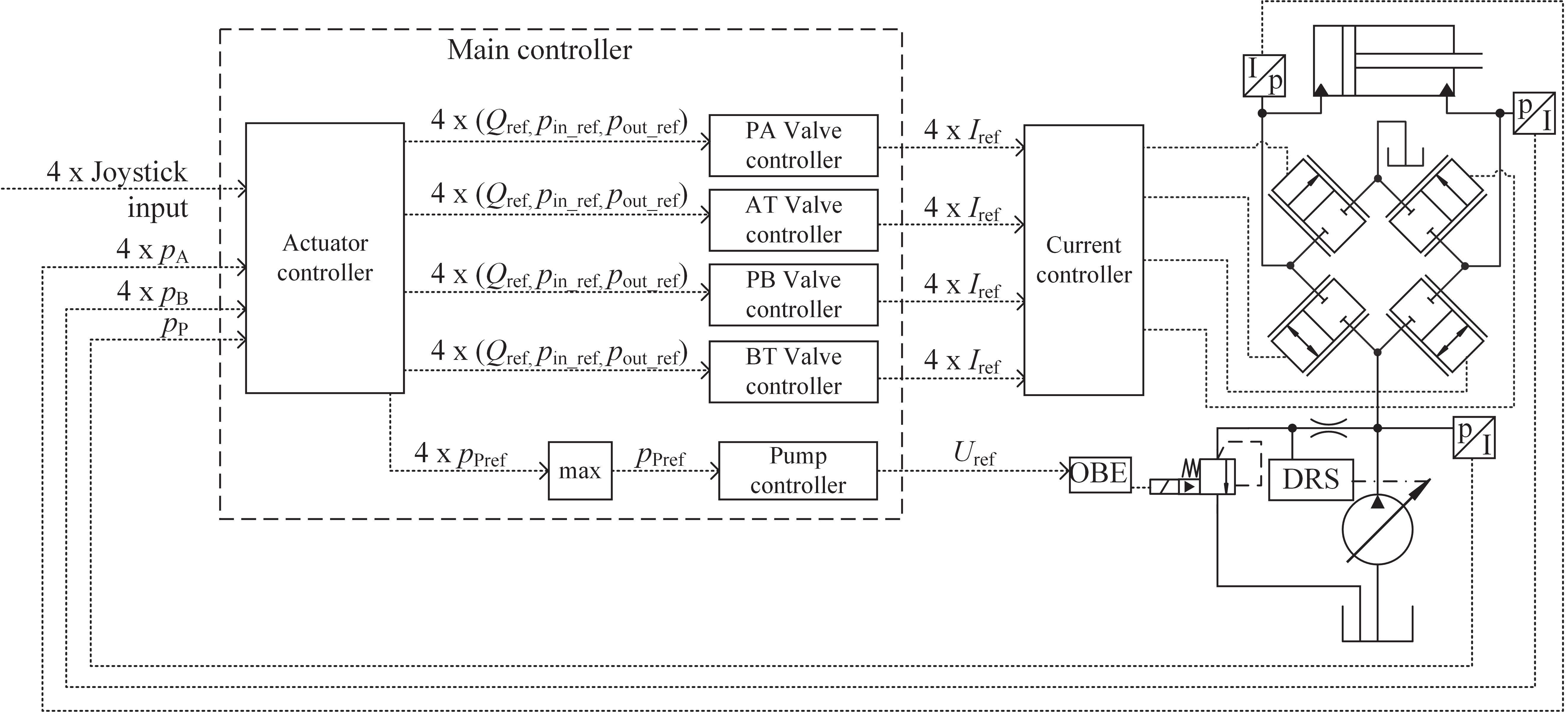
Figure 5 Simplified diagram of the control architecture. Only single actuator and its control valves are drawn, even though four actuators are implemented in the demonstrator.
Model-based valve controller with electrical pressure compensation
The valve controller is based on the steady-state model of the control valve. The model takes into account the inlet and outlet pressure, maximum flow capacity of the valve and the nonlinear relationship between the coil current and relative opening of the valve. The flow capacity of the valve is characterized by its value:
| (1) |
where is the nominal flow rate of valve driven with maximum coil current at nominal pressure difference . The modelled maximum flow of the valve and the flow reference are compared to achieve a target opening (0…1) at current pressure difference, which is defined by the inlet and outlet pressure references:
| (2) |
It is worth to note, that the pressure difference received by the model is limited to user set minimum value to avoid unreasonable valve behaviour close to zero pressure difference. Finally, the target opening is converted into coil current reference using a look-up table to linearize the static valve characteristics.
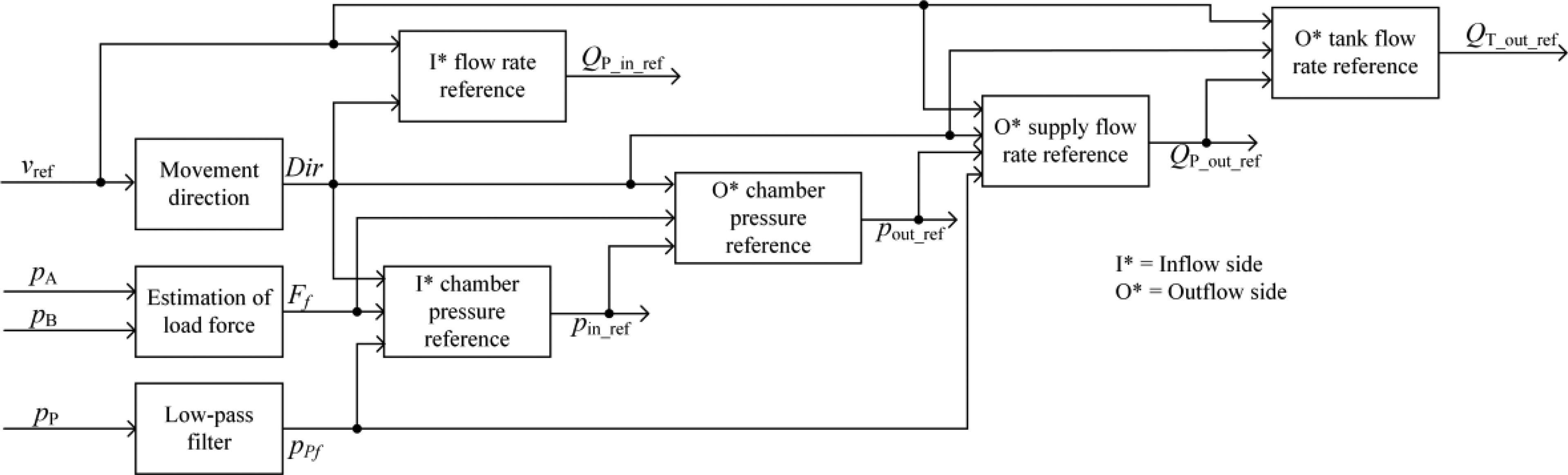
Figure 6 Simplified structure of the actuator controller.
Actuator controller
Upper-level view of the actuator controller is given in Figure 6. The purpose of the actuator controller is to give the valve controllers such pressure references and flow references that the user set actuator velocity command is reached, and unnecessary energy losses are avoided. The unnecessary losses are avoided by selecting correct control mode based on measured supply pressure and load force estimate, which is calculated from measured and low-pass filtered chamber pressures. To enable seamless transition between inflow-outflow control mode and differential control mode while simultaneously avoiding unnecessary energy losses, following key requirements must be fulfilled during the transition:
1. Chamber pressure references should be continuous
2. The flow rates to actuator ports should follow the velocity command throughout the transition
3. Direct flow from supply line to return line through the control valves should be avoided
4. The rate of change in valve flow rate references should not exceed the valve dynamics or supply pump dynamics
The first requirement is met by maintaining a constant pressure difference of (1.5 MPa) on the inflow-side, whenever possible. Such inflow-side pressure reference can be used in both inflow-outflow mode and differential mode. However, care must be taken to avoid too high or low outflow-side pressures. Therefore, the inflow-side pressure reference is calculated for all extending control modes as:
| (3) |
and for all retracting control modes as:
| (4) |
where is the measured and low-pass filtered supply pressure, is the maximum chamber pressure (23 MPa), is the minimum outflow-side pressure (1 MPa), and are the piston side and rod side chamber areas respectively and is the load force calculated from measured and low-pass filtered chamber pressures. The outflow-side chamber pressure is calculated from force equation using the estimated load force and the inflow-side chamber pressure reference.
The requirements 2-4 are fulfilled by suitable valve flow references and proper application of the continuously variable control modes (presented in Figure 3). It is worth to note, that the CVMs induce slightly increased throttling losses, when compared to distinct control modes, but direct flow from supply line to tank line can still be avoided. Furthermore, they enable the smooth transition between the control modes. In the CVMs used in this paper, the inflow-side of the cylinder is always fed from the supply line. Therefore, the inflow-side flow rate reference is calculated directly from the velocity reference and inflow-side cylinder chamber area. The outflow-side is drained partly to the tank line and partly to the supply line such that the combined flow corresponds to the velocity command (Requirement 2). The seamless transition between the control modes is possible by continuous variation of the flow ratio between the tank line and supply line control valves. Successful sharing of the flow requires the outflow-side chamber pressure to exceed the supply pressure (Requirement 3). The direction of the supply flow depends on movement direction in the CVMs: the supply flow rate is always positive in the extending direction. In the retracting direction, the direction of the supply flow rate depends also on sharing of the outflow between the supply- and tank-side control valves.
The throttling losses of the extending continuously variable control mode are compared to the distinct control modes in Figure 7. The figure presents also the corresponding valve flow rates as a function of load force. The system parameters are the same as used in Figure 2. The continuously variable mode stays in full inflow-outflow connection, until the load force is small enough and the outflow-side chamber pressure exceeds the supply pressure by minimum pressure difference (Requirement 3). As the load force further decreases, the outflow-side pressure difference increases. The continuously variable mode reaches full differential connection, when the outflow-side pressure difference exceeds the user set target ( MPa). The parameter should be tuned such that the valve and pump dynamics are not exceeded in mode transitions (Requirement 4). As can be seen in the figure, the continuously variable mode never exceeds the power loss of the inflow-outflow control mode but consumes more power than the pure differential control mode in the transition phase.
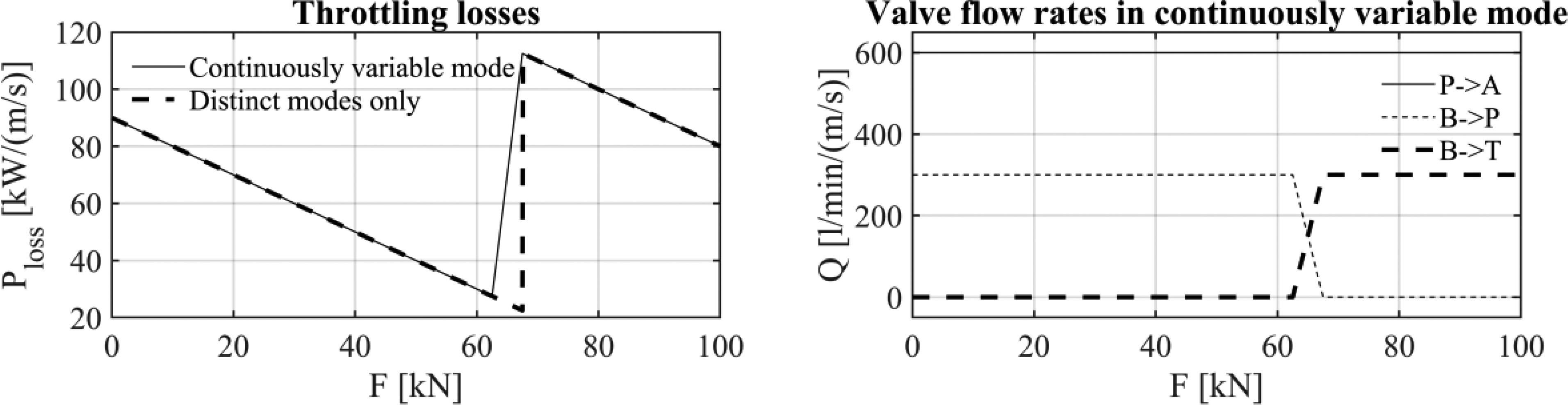
Figure 7 Throttling losses of the continuously variable control mode and corresponding valve flow rates in extending movement.
Experimental Study
Test setups
Figure 8 presents the hydraulic diagram of the baseline system. Note that the local pressure compensators of the valves are omitted to improve readability of the diagram. In this study, the four actuators (lift, luffing, extension and slewing), which control the movement of the boom, are investigated. These actuators are controlled with conventional load sensing 4-way pressure compensated proportional valves (Parker K170LS) in the baseline system. The rest of the actuators: grabber, grabber rotation and steering actuators are also controlled with this valve. Loading of the brake circuit accumulator is controlled with a separate On/Off-valve. Pump of the baseline system is a 130 cc Rexroth A11 with hydraulic load sensing controller. Drive and auxiliary pumps are also driven by the diesel engine and their effect on diesel load is considered in the analysis as parasitic loss; therefore, they are presented also in the hydraulic diagram (in grey).

Figure 8 Hydraulic diagram of the baseline system.
Trafag 25 MPa pressure transducers are used to measure the supply and the cylinder chamber pressures. The cylinder chamber pressures are measured from actuator ports of the K170LS-valve. Cylinder piston positions are not directly measured (except for the boom extension), but they are calculated from the measured joint angles. Lift and luffing angles are measured with incremental encoders. Slewing angle is measured with absolute angle resolver. Extension cylinder position is measured with incremental draw-wire sensor. Details of the joint angle and draw-wire measurement configuration can be found in [Nurmi 2017]. Rotation speed of the diesel engine (and the pump) is measured with a Hall sensor. Flow of the pump is measured with Volutronik VC5 gear tooth flow meter. Furthermore, the joystick commands of all boom control actuators and valve current references of the studied four actuators are measured.
In the modified setup, the valves that control lift, luffing, extension and slewing cylinders are replaced with the independent metering valves (Husco EHPV 150 lpm). Modified hydraulic diagram is presented in Figure 9. Because the independent metering valves do not provide a hydraulic LS signal, the hydraulic LS-system is converted into electronic LS-system. The pump is the same as in baseline system, but LS pressure is generated with a proportional pressure relief valve (Rexroth DBETB) that is connected to pump supply line via small orifice. Grabber, grabber rotation, steering and brake are controlled similarly as in the baseline system.
In order to sense the LS pressure of the grabber, steering and brake circuits, a Trafag 25 MPa pressure sensor is added in the load sensing line. Otherwise, the measurement configuration is the same as with the baseline system.
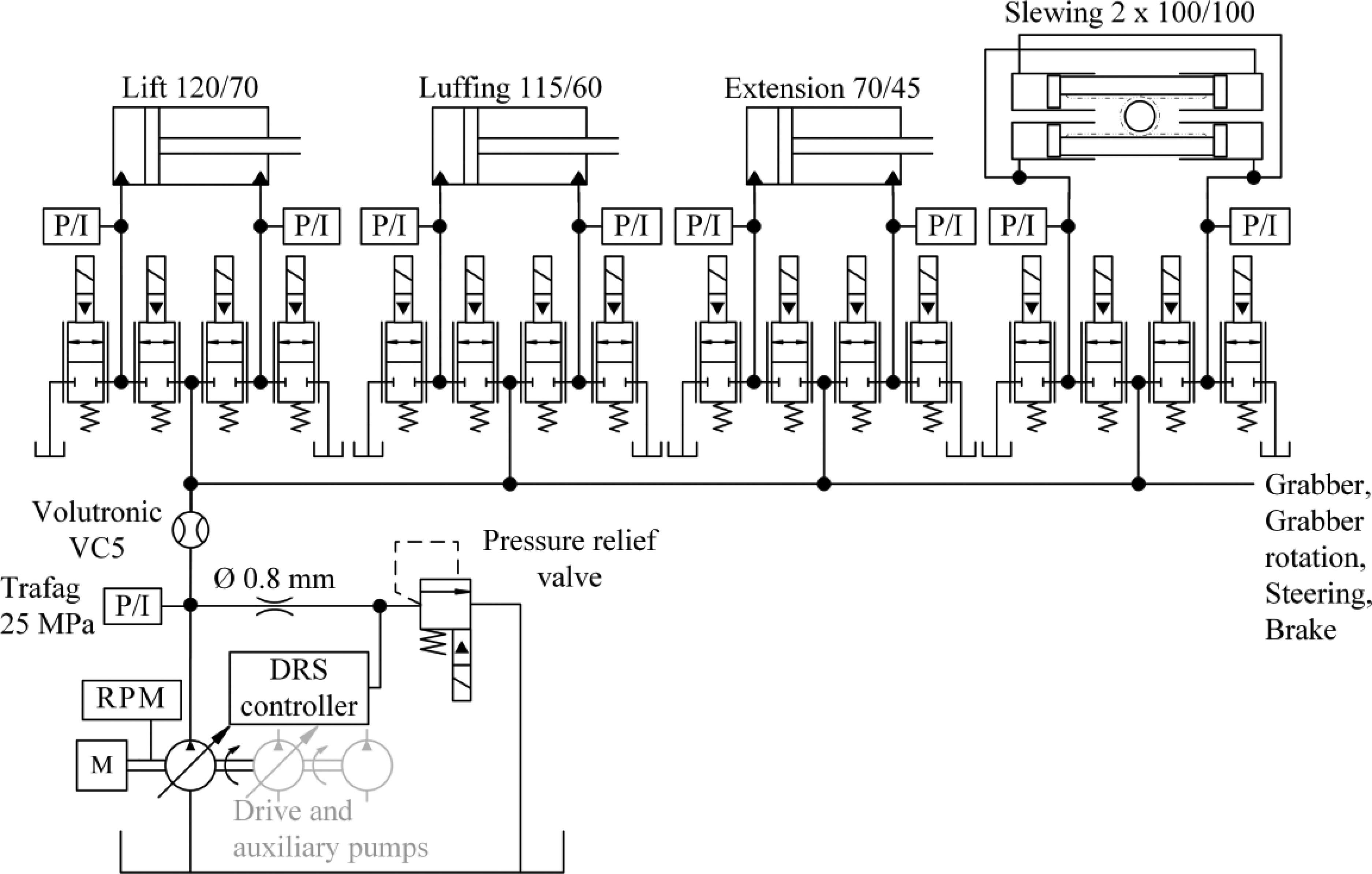
Figure 9 Hydraulic diagram of the independent metering valve-based system.
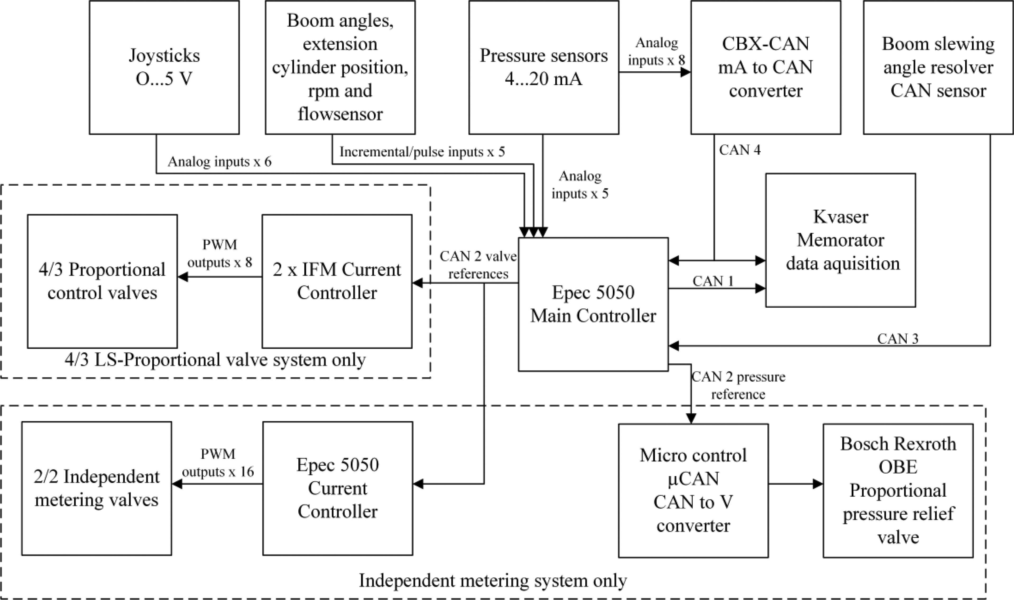
Figure 10 The control system.
Physical devices of the control and measurement system and their communication network are illustrated in Figure 10. The heart of the control and measurement system is the main controller. The main controller is an Epec 5050 CAN-controller that has analogue, incremental/pulse inputs and PWM outputs. The machine operator controls the boom movements with joysticks; joysticks have analog outputs which are measured with the main controller. Rotation speed of the diesel engine is measured with Hall sensor and pulse input. Cylinder chamber and supply pressures are measured with analog pressure sensors. Some of the pressure sensors are measured with main controller’s analog inputs. Rest of the pressures are measured with CAN converter that sends measured pressures to main controller via CAN bus. Lifting and luffing angles, extension cylinder position and flow are measured with incremental inputs. Boom slewing angle is measured with resolver that sends position via CAN to main controller. Data acquisition is done with Kvaser Memorator, which is capable of recording two CAN buses. The main controller sends signals, which are desired to be recorded, to the Memorator via CAN bus. The Memorator records also pressures measured with CAN converter. Position of the lift, the luffing and slewing cylinders are calculated from boom geometry in MATLAB. The actuator velocities are also post-processed in MATLAB: the velocity is differentiated from the measured position and the velocity is filtered with a second order low-pass filter having corner frequency of 10 Hz. The filtering is performed from first to last element and then repeated in opposite direction to avoid phase shift. The effective order of the filter is thus four.

Figure 11 Excerpt of the measured load cycle. Baseline system.
In both baseline and independent metering systems, the main controller sends valve references to current controllers. In the baseline system, the 4/3-proportional valves are controlled with an IFM CR2031 current controller. In the independent metering valve system, the 2/2-proportional valves are controlled with second Epec 5050, which is used as current controller. In the independent metering valve system, the LS-pressure is produced with proportional pressure relief valve. The main controller sends the supply pressure reference via CAN converter to the pressure relief valve.
The measured load cycles consist of two loading cycles and two unloading cycles for both the baseline and the independent metering system. During the measurements the forwarder is stationary at even field. In the loading cycle, the logs are lifted from a pile at the ground into the load space of the forwarder. In the unloading cycle, the logs are piled back to the ground. The number of logs used in the cycles is such that the logs fill the whole load space of the forwarder. The same logs are used in each measured load cycle. These work cycles have been driven by a professional machine operator.
Results of the baseline forwarder
Figure 11 presents an excerpt of the measured loading cycle with the baseline system. Measured velocity, output power and the chamber pressures (solid piston side, dashed rod side) are shown for each actuator. The figure presents also the measured flow rate and supply pressure of the pump. The hydraulic output power of the pump presented, is calculated from the above-mentioned flow rate and supply pressure.
The data presented in the figure includes two lifting cycles. At the beginning of the data, the boom is in low position and the logs are ready in the grabber to be lifted. The cycle starts by retracting the extension and simultaneously extending the lift actuator. While the lift actuator is driven, the slewing motion starts. After completing the lifting and slewing motion, the lift actuator is slightly retracted, the luffing actuator is extended, and the logs are dropped into the load space. Roughly at s, the boom is lifted above the load space and slewing motion starts. During slewing, the lift and luffing actuators are retracted, and the extension is driven forward to reach next pile of logs. Roughly at the next loading cycle starts. Although only two lifting cycles are shown in the figure, the particular work cycle consist of 21 lifting cycles in total.
Table 1 Summary of the results for the baseline system
| Loading 1 | Loading 2 | Unloading 1 | Unloading 2 | |
| Fuel rate [l/h] | 6,03 | 6,09 | 5,99 | 6,04 |
| Fuel amount [l] | 1,04 | 1,13 | 0,97 | 0,90 |
| Pump output [kJ] | 4910 | 5487 | 4543 | 4273 |
| Est. valve input* [kJ] | 4376 | 4916 | 3805 | 3567 |
| Actuator output* [kJ] | 566 | 610 | 158 | 174 |
| Est. valve losses* [kJ] | 3810 | 4306 | 3647 | 3393 |
| Duration [s] | 623 | 666 | 582 | 535 |
| Average RPM | 1598 | 1591 | 1598 | 1594 |
| * Energy related to the four main actuators | ||||
Table 1 presents an overview of the measurement results of the baseline system. The output energy is estimated from the measured actuator velocity and estimated load force. The load force is calculated from the measured chamber pressures thus including the piston friction. The hydraulic output power of the pump is calculated as a product of measured supply pressure and supply flow rate. To estimate the valve losses generated by the studied four main actuators, the input energy of the main actuators needs to be estimated. The estimate is calculated as product of measured supply pressure and estimated input flow rate of the valve. The input flow rate is estimated using measured velocities of the actuators and their chamber areas. The estimate is used instead of the measured pump flow rate as part of the pump flow is consumed by the grabber and the braking circuit (on average 13%). Finally, the consumed fuel amount and the average fuel rate are estimated using the efficiency model of the open-circuit pump and the diesel engine adapted from [Huova 2018].
Results of the independent metering valve based forwarder
Figure 12 presents an excerpt of the measured loading cycle with the independent metering valve based system. The same graphs are shown as for the baseline system.
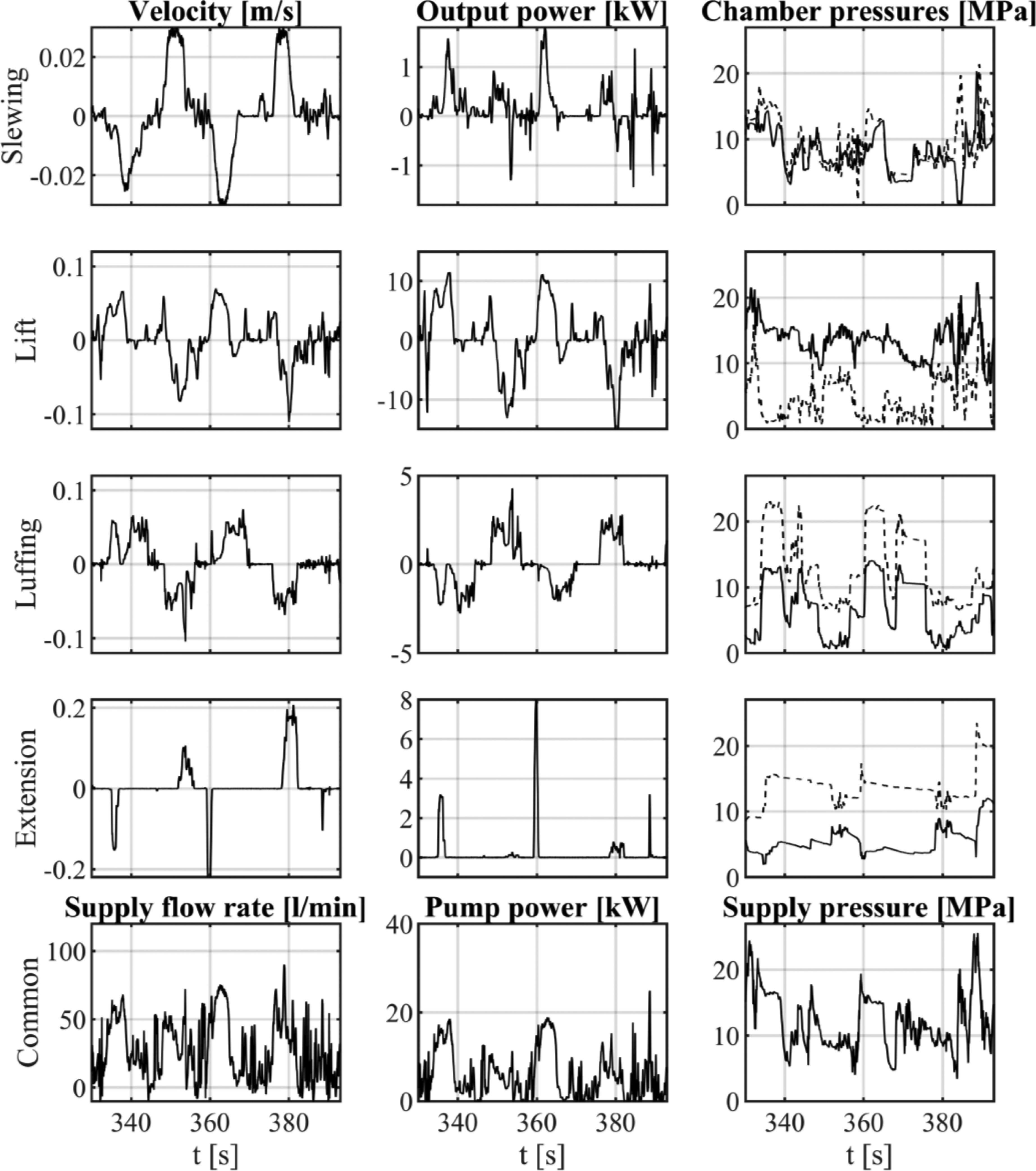
Figure 12 Excerpt of the measured load cycle. Independent metering valve based system.
The baseline system features a single-acting lift actuator, where the rod-side is connected to tank line. In the independent metering valve based system, the rod-side chamber is actively controlled. This enables lowering movements in differential connection, which results in energy recuperation. The flow generated by the lift actuator is used in other simultaneously moving actuators. The luffing actuator performs most of the extending movements in differential connection, which decreases the supply flow rate. Also the extension actuator is driven in differential connection to extending direction. However, the baseline system is configured to do the same.
Figure 13 presents a small excerpt of the work cycle driven with the independent metering valve-based system. The diagram shows the piston position x of the luffing cylinder and its velocity v. Together with the velocity is shown the velocity reference given by the machine operator. The measured chamber pressures and and the supply pressure is presented as well as the reference currents of the control valves and .
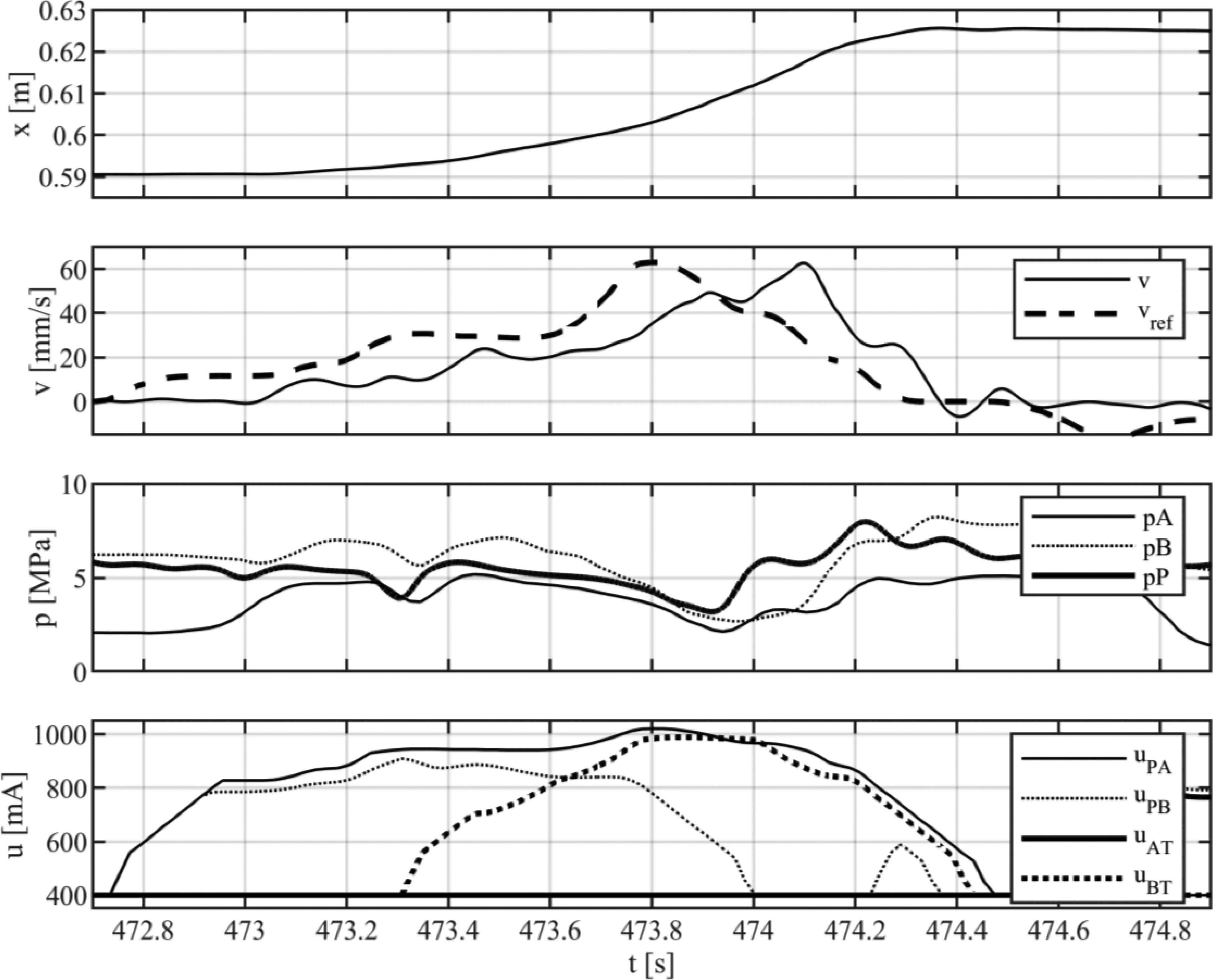
Figure 13 Luffing actuator performing continuous mode switches.
The excerpt shows several continuous mode switches. The motion starts in extending differential mode. At roughly , the control mode starts to change towards inflow-outflow mode and reaches pure inflow-outflow control at . However, right before the motion ends, the valve PB is commanded open again due to increased supply pressure, which extends the force range of the differential connection.
The Figure 14 shows the distribution of the measured actuator velocities for the baseline forwarder and for the forwarder controlled by the independent metering valves. The data of all four measured work cycles are combined (Loading 1, Loading 2, Unloading 1, Unloading 2) in the histograms. It is worth to note that the smallest velocities are discarded due to the measurement noise. The purpose of the histograms is to enable a comparison of actuator velocities reached during the work cycles. The height of the bar represents the portion of the work cycle, in which the actuator is driven at the particular velocity. The lowest row presents the distribution of pump flow rate and output power of the pump. The peak flow rates and peak powers are presented also in the partial enlargements to facilitate the comparison.
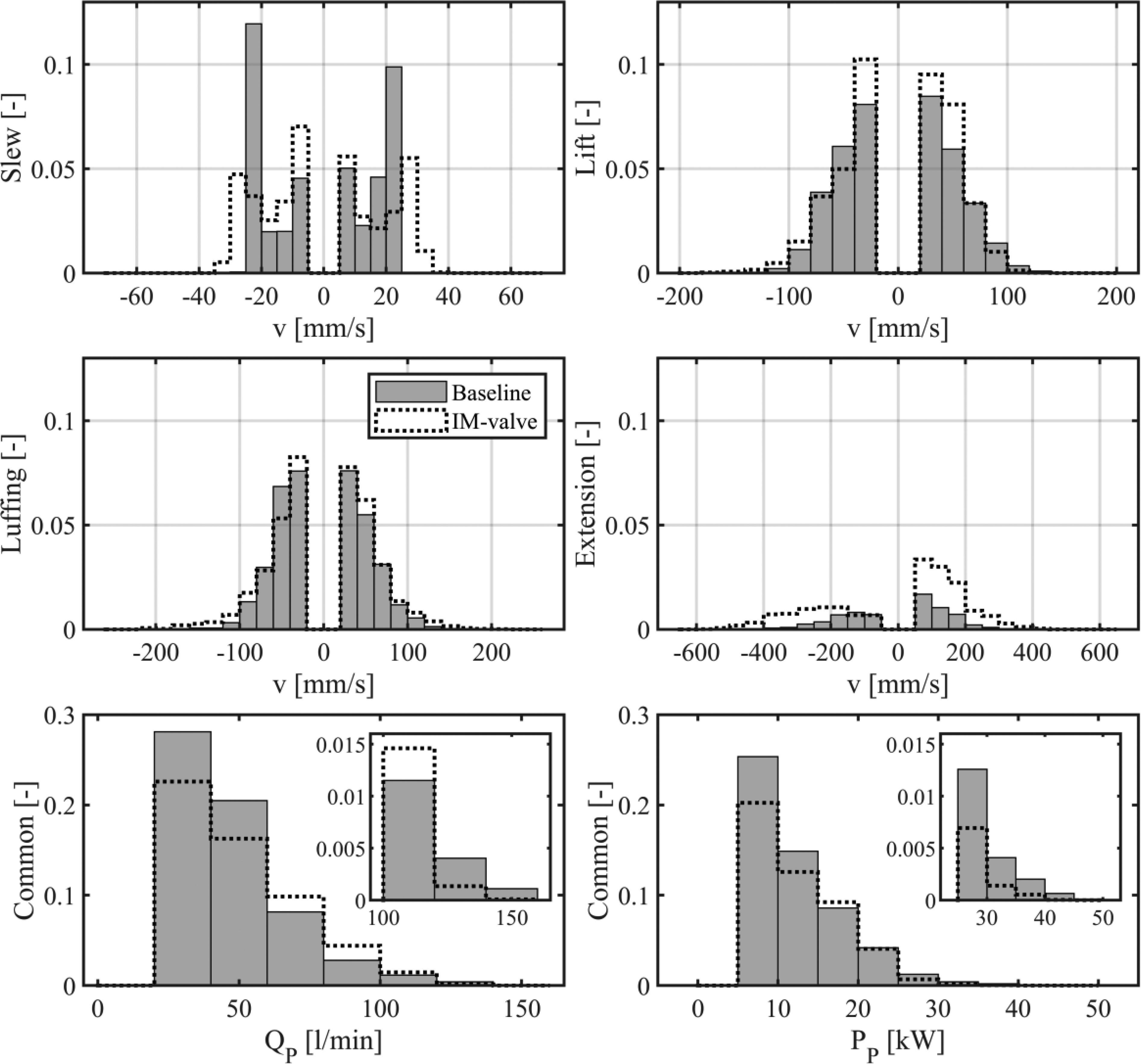
Figure 14 Distribution of actuator velocities in the measured working cycle. Lowest row presents the distribution of pump flow rate and hydraulic output power of the pump.
The summary of the measurement results for the independent metering system are given in the Table 2 together with the estimated fuel rate and amount.
Table 2 Summary of the results for the independent metering system
| Loading 1 | Loading 2 | Unloading 1 | Unloading 2 | |
| Fuel rate [l/h] | 5,01 | 5,34 | 5,13 | 5,22 |
| Fuel amount [l] | 0,83 | 0,69 | 0,75 | 0,74 |
| Pump output [kJ] | 3728 | 3519 | 3526 | 3599 |
| Actuator output* [kJ] | 447 | 436 | 230 | 196 |
| Duration [s] | 595 | 468 | 528 | 509 |
| Average RPM | 1418 | 1412 | 1419 | 1413 |
| * Energy related to the four main actuators | ||||
Discussion
Figure 13 demonstrates the mode switching capability of the independent metering valves and the controller developed. The basis of the smooth mode switch is the use of so called continuously variable modes. Figure shows also a relatively long delay of approximately 200 ms from the joystick input (velocity reference) to measured actuator velocity. Ignoring the delay, the velocity command is tracked relatively well despite the multiple mode switches occurring during just 1.7 s long trajectory. The delay consists of multiple smaller delays accumulated in the system: CAN-network based communication between the master (main) and slave (valve current) controllers, dynamics of the current control and valve delay. As the operation of the crane is predictable and deterministic, the operator can adapt to the delay. In this particular test, the subjective evaluation of the professional operator was, that the operability of the machine improved when replacing the conventional setup with the independent metering system.
Figure 14 compares the distribution of measured actuator velocities between the baseline and the independent metering system. Slewing motion was slightly saturated in the baseline system due to low joystick command gain. This resulted in machine operator driving the slew actuator often at full velocity command, which is shown as strong distribution of the data in the 20…25 mm/s range. Slightly higher velocities were allowed in the independent metering system showing already more even distribution. Lift and luffing actuators were driven quite similarly in both systems. The extension was operated more in the independent metering system, than in the baseline system, but the usage was still less frequent compared to other actuators. Overall, it can be concluded that the independent metering valve based system enabled at least as high movement velocities as the baseline system. Due to the use of differential connection and elimination of unnecessary throttling losses, this was achieved with lower peak power and flow rate of the pump as presented in the lowest row of Figure 14. This enabled the lowering of the diesel engine RPM in the independent metering valve based system.
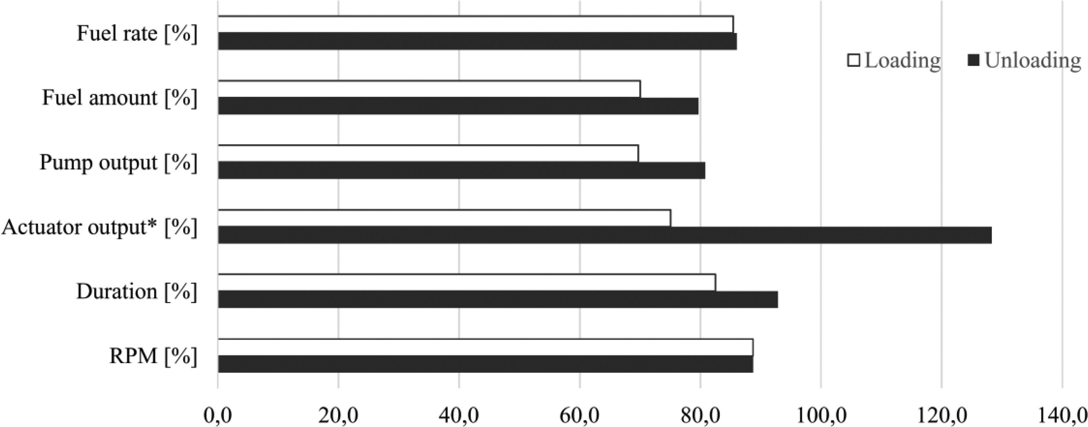
Figure 15 Summary of the results. Independent metering valve based system is compared to the baseline system (baseline 100%). *Energy related to the four main actuators.
Figure 15 presents a summary of the measurement results. The independent metering valve based system is compared to the baseline system, which is set to 100%. The average duration of the unloading cycle was decreased approximately 7 percent when comparing the independent metering valve based system to the baseline. In loading cycle, the difference is 17 percent. The difference is possibly explained by the fact, that the handling and the operator feel was improved as commented by the professional machine operator. The output energy of the pump was reduced 19–30% depending on the work cycle type. This is mainly due to improved energy efficiency of the independent metering valve based system. The mechanical output energy of the actuators was decreased in the loading cycle. This is due to a fact that the water content of the logs was significantly smaller during the summertime (August) when the independent metering valve based system was measured. The measurements with the baseline system were carried out eight months earlier in wintertime (December). The same phenomenon is visible in the unloading cycle, where the output energy is increased: as the logs are lighter, the absolute value of the negative energy produced in the load lowering movement is smaller and therefore the total output energy is more positive. The total output energy is positive because the energy loss produced by the friction forces of the system is greater than the negative energy received from the load lowering. However, the effect of different output energies in the baseline measurements and in the measurements of the independent metering valve based system is not significant as the output energy is on average less than 10% of the hydraulic input energy in these working cycles. In other words, majority of the energy produced by the pump is used to overcome the throttling losses. The diesel engine RPM was set to approximately 1600 during the baseline measurements to achieve the performance that the machine operator considered adequate. In the modified setup, the diesel engine RPM could be lowered to approximately 1400 without decrease in performance, when compared to the baseline system. This improves the efficiency of the diesel engine and partly explains the reduced fuel rate and amount. However, in the efficiency map utilized in calculation, the average improvement is only 3%, when RPM is lowered from 1600 to 1400 RPM. The estimated idle losses of the auxiliary pumps drop from 3.9 kW to 3.5 kW due to the decreased RPM as well.
The estimated average fuel rate was reduced by %, when utilizing the independent metering control. Due to the shorter duration of the cycle, the estimated amount of fuel consumed was reduced more significantly: %.
Conclusions
Independent metering control was applied to a forestry forwarder. 2/2 proportional control valves were utilized together with continuously variable modes. The independent metering-controlled forwarder crane was experimentally tested in log loading and unloading working cycles. The same working cycle was performed also with the 4/3 proportional valve-based baseline forwarder. The throttling losses were significantly reduced, and therefore the hydraulic output power of the pump was reduced by 25%.
Due to smaller throttling losses, it was possible to run the diesel engine at reduced rotational speed. Due to reduced losses and improved engine operation point, the estimated fuel consumption was reduced by 25%.
Acknowledgements
This work was supported by the Business Finland / Tekes under Grant 1604/31/2016 (Challenge Finland project). Sincere thanks to the operator Manne Viljamaa from Tampere University of Applied Sciences.
References
Ding, R.; Xu, B.; Zhang, J.; Cheng, M. Bumpless mode switch of independent metering fluid power system for mobile machinery. Automation in Construction 68. 2016, Volume 68, pp. 52–64.
Elfving, M.; Palmberg, J-O.; Jansson, A. Distributed Control of Fluid Power Actuators – A Load Sensing Application of a Cylinder With Decoupled Chamber Pressure Control. Proceedings of the Fifth Scandinavian International Conference on Fluid Power. Linköping, Sweden, 1997.
Eriksson B.; Rösth, M.; Palmberg, J-O. A High Energy Efficient Mobile Fluid Power System – Novel System Layout and Measurements. Proceedings of the 6th International Fluid Power Conference. Dresden, Germany, April 1–2, 2008.
Eriksson B.; Rösth, M.; Palmberg, J-O. Energy saving system utilizing LQ-technique design. Proceedings of the Seventh International Conference on Fluid Power Transmission and Control. Hangzhou, China, 7th–10th April, 2009.
Eriksson, B. Mobile Fluid Power Systems Design with a Focus on Energy Efficiency. Doctoral dissertation, Linköping University, Linköping, Sweden, 2010.
Ge, L.; Dong, Z.; Huang, W.; Quan, L.; Yang, J.; Li, W. Research on the Performance of Hydraulic Excavator with Pump and Valve Combined Separate Meter In and Meter Out Circuits. Proceedings of the IEEE International Conference on Fluid Power Mechatronics, 2015.
Hansen, A.; Pedersen, H.; Andersen, T.; Wachmann, L. Investigation of Energy Saving Separate Meter-in Separate Meter-out Control Strategies. Proceedings of the Twelfth Scandinavian International Conference on Fluid Power. Tampere, Finland, May 18–20, 2011.
Hu, H.; Zhang, Q.; Realization of Programmable Control Using a Set of Individually Controlled Electrohydraulic Valves. Int. J. of Fluid Power. 2002, Volume 3, Issue 2. pp. 29–34.
Huova, M.; Tammisto, J.; Linjama, M.; Tervonen, J. Fuel Efficiency Analysis of Selected Hydraulic Hybrids in a Wheel Loader Application. Proceedings of the 2018 Bath/ASME Symposium on Fluid Power and Motion Control. Bath, UK, September, 12–14.
Jansson, A.; Palmberg, J-O. Separate Controls of Meter-in and Meter-out Orifices in Mobile Hyraulic Systems. SAE Technical Paper 901583. 1990, https://doi.org/10.4271/901583.
Koivumäki, J.; Mattila, J. An energy-efficient high performance motion control of a hydraulic crane applying virtual decomposition control. Proceedings of IEEE/RSJ International Conference on Intelligent Robots and Systems, 2013, pp. 4426–4433.
Mattila, J; Virvalo, T. Energy-efficient Motion Control of a Hydraulic Manipulator. Proceedings of the IEEE International Conference on Robotics & Automation. San Francisco, USA, April 2000.
Nurmi, J; Mattila, J. Global Energy-Optimal Redundancy Resolution of Hydraulic Manipulators: Experimental Results for a Forestry Manipulator. Energies 2017, 10, 647; doi:10.3390/en10050647.
Shenouda, A. Quasi-Static Hydraulic Control Systems and Energy Savings Potential Using Independent Metering Four-Valve Assembly Configuration. Ph.D. Thesis, Woodruff School of Mechanical Engineering, Georgia Institute of Technology. July 5, 2006.
Yao, B.; Liu, S. Energy-Saving Control of Hydraulic Systems With Novel Programmable Valves. Proceedings of the 4th World Congress on Intelligent Control and Automation. Shanghai, China, June 10–14, 2002.
Yuan, Q.; Lew, J. Modelling and Control of Two Stage Twin Spool Servo-Valve for Energy-Saving. Proceedings of the American Control Conference. Portland, OR, USA, June 8–10, 2005.
Biographies

Mikko Huova received a D.Sc. degree at Tampere University of Technology, Finland, in 2015. The topic of his thesis is related to energy efficient digital hydraulic systems. He is continuing research on energy efficiency of mobile machines as a postdoctoral researcher at Tampere University. The areas of interest include control design, modelling and simulation.

Jyrki Tammisto received a M.Sc. degree at Tampere University of Technology, Finland in 1998. Currently he is working as project researcher at the Automation Technology and Mechanical Engineering Unit, Tampere University.

Matti Linjama obtained a D Tech degree at Tampere University of Technology, Finland in 1998. Currently, he is an adjunct professor at the Automation Technology and Mechanical Engineering Unit, Tampere University. He started the study of digital hydraulics in 2000 and has focused on the topic since then. Currently, he is leader of the digital hydraulics research group and his professional interests include the study of hydraulic systems with high performance and energy efficiency.
International Journal of Fluid Power, Vol. 21_2, 147–168.
doi: 10.13052/ijfp1439-9776.2121
© 2020 River Publishers