A Cost-Effective Electro-Hydraulic Actuator Solution with Open Circuit Architecture
Shaoyang Qu1,*, David Fassbender1, Andrea Vacca1 and Enrique Busquets2
1Maha Fluid Power Research Center, Purdue University, Indiana, USA
2Bosch Rexroth, South Carolina, USA
E-mail: qu82@purdue.edu
*Corresponding Author
Received 25 November 2020; Accepted 17 February 2021; Publication 29 May 2021
Abstract
With the recent electrification trend in the fluid power area, more research has been incentivized to propose cost-effective and energy-efficient solutions for hydraulic systems. Hence, electro-hydraulic actuator (EHA) architectures receive increasing attention. The paper proposes a novel open-circuit EHA architecture, with the goal to obtain a cost-effective solution for mobile applications while maximizing the overall system efficiency. The proposed EHA is capable of meeting or exceeding traditional off-road machine performance, therefore enabling further electrification of off-road machines. Four-quadrant functionality, covering the full speed range, is achieved by a combination of a variable electro-hydraulic drive and valves with different functions. Focusing on the steady-state performance, the functionality is validated by numerical as well as experimental methods. A simulation model based on the Amesim environment and a dedicated test setup was developed to verify the performance. The good match between simulation and experimental results confirms the potential of the formulation approach of the proposed EHA for applications with different duty cycles and power levels.
Keywords: Electro-hydraulic actuator, open circuit, 4-quadrant functionality.
1 Introduction
For decades, fluid power systems serve in a wide spread of industries. However, the low-efficiency of current state-of-the-art hydraulic drives, which can be low as 22% on average, incentivizes research on hybrid systems with the trend of electrification [1, 2]. The market’s increasing interest and requirements towards a kind of cost-effective, energy-efficient, industrial solution turn the spotlight on EHAs. Individualization of fluid power systems has a significant, positive impact on energy efficiency, but brings up the conflict between costs and flexibility [3]. The capability of avoiding throttling losses and energy recovery are merits of the EHA in terms of energy efficiency, including rotary and linear motion control as applications [4]. Moreover, with the fast urbanization in global areas nowadays, the regulation on exhaust emissions makes the EHA a popular alternative to diesel-driven machines [5].
With the advantages of compactness, in recent years, efforts have been made to apply the EHA architectures in some low power-level applications, such as aerospace, mobile applications, and small size robots. Driving by the goal of ‘a more electric aircraft’, the EHA has been utilized in the primary flight control of the F-18 system and the Airbus A340 [6, 7], the active vibration isolation on rotorcraft [8], and the motion control of seats in the first-class [9]. The high-power density of the EHAs attracts the attention of robotics for efficient and compliant actuation [10]. An existing example is assisting amputees with powered ankle prosthesis [11]. For mobile applications, the potentially recoverable energy in one duty cycle is high [12]. The EHA can recuperate this recoverable energy and store it in batteries and hydraulic accumulators [13]. An energy analysis has been conducted on an electro-hydraulic steering system for buses [14]. Parker Hannifin has proposed a compact EHA product using gear pumps under the size of 0.53 cc/rec, featuring high power density with lightweight [15, 16]. Another study utilizes a high-speed electric unit and a gearbox to increase the power density for the implementation of the EHA on mobile applications [17]. Nevertheless, other than the range of applications, the power levels of EHAs are rather limited as shown in the previous examples, and EHAs have failed to penetrate the markets of heavy-duty mobile machines. For this reason, the self-locking capability of EHAs and power levels scalable up to 80kW have been studied for future applications [18, 19]. The goal to apply EHAs on commercial hydraulic machines also drives the research on energy-saving performance. Studies show that energy consumption can be reduced by 75% based on a typical excavator boom working cycle [20], and the energy recovery efficiency can reach up to 45% with an accumulator-motor-generator system [21].
The main challenge to implement the current EHA solutions on mobile applications is the high cost of the electrified system. The cost of the EHAs is mostly determined by the electro-hydraulic units (EHU). Therefore, the classification of EHA has been studied in detail with regard to different types of EHUs [22], comprising a variable-speed electric motor and a fixed-displacement pump solution (VMFP), or a constant-speed motor and a variable-displacement pump solution (CMVP). Comparing these two configurations for the EH drives, a study on the injection molding machine shows that VMFPs win in terms of cost and energy efficiency [23]. For this reason, the EHA solution proposed in this paper adopts the VMFP as the EHU.
However, using the fixed-displacement pump, one of the most significant technical challenges for the EHAs is the speed limit of the hydraulic unit [24], which prohibits proper low-speed actuation. Moreover, the use of accumulators in most closed-circuit EHA architectures increases the costs and makes it harder to achieve the self-sustainability of the system over the whole lifetime. Addressing such challenges, a novel EHA with open-circuit architecture is proposed in the paper, introducing the bypass valve to the circuit for the speed control. Comparing to existing EHA solutions, the proposed architecture addresses the following challenges:
• The proposed architecture utilized the VMFP as the EHU, making the system a cost-effective EHA solution.
• The proposed EHA covers the full speed range of the actuation (0-max) in four quadrants, by using a speed controlled fixed-displacement hydraulic unit.
• The proposed solution permits us to reach actuation faster than that allowed by the hydraulic unit itself. Therefore, the sizing of the EHU in the system has more flexibility. As a result, it avoids oversizing the EHU and decreases the overall cost.
The paper is structured in the following order: Section 2 describes the system configuration of the proposed EHA. Section 3 demonstrates the development of the simulation model and the results. Section 4 shows the experimental setup and measurements to verify the functionality of the proposed system. Finally, Section 5 concludes the work in the paper and gives the outlook for future work.
2 System Configuration
2.1 Hydraulic Circuit
The definition of the open or closed circuit is determined by the way the pump is used. In a closed circuit, both sides of the actuator directly connect to the pump, of which the high-pressure port is not pre-defined but switching. On the other hand, if the pump only operates with high pressure on one side and is directly connected to a low-pressure reservoir on the other side, the circuit is open [25]. The proposed open-circuit system configuration is given in Figure 1. The EH drive consists of a fixed-displacement pump (HP) and a variable-speed electric motor (EM). Although the HP operates only in two quadrants in terms of pressure and speed, a 4/3 directional valve (DV) guarantees the 4-quadrant functionality of the actuator, which is a single-rod double-acting cylinder (CYL) in this study. Two relief valves (RV1, RV2) are instrumented on both sides of CYL to avoid damage due to over-pressurization. The combination of check valves (CV1, CV2) addresses the cavitation issues, which may appear when high flow is needed from a reservoir during an assistive operation. A 2/2 proportional valve works as a bypass (BPV) parallel to the CYL. Slow or fast actuation exceeding the pump’s speed range is possible with the help of BPV. A filter (FL) in combination with a check valve (CV3) is present for maintenance.
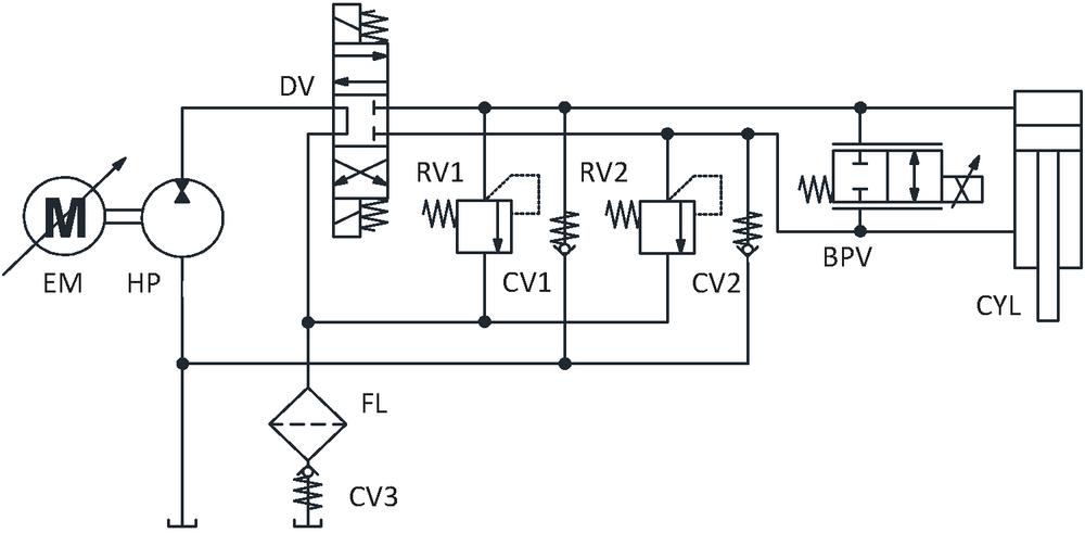
Figure 1 Configuration of the proposed system.
2.2 Functionality in Four Quadrants
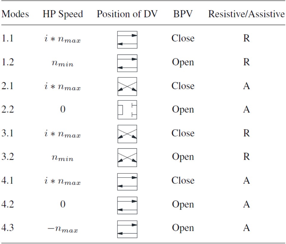
In terms of actuation velocity and applied load from the user interface, all working modes can be summarized in one 4-quadrant map, as shown in Figure 2. The x-axis represents the load () applied on CYL, while the y-axis shows the actuation velocity (. When the direction of is opposite towards the direction of , which is given in the first and third quadrants, the system works in resistive modes. Vice versa, modes in the second and fourth quadrants are assistive, in which case HP and EM work to regenerate energy. Red/blue lines highlight high/low pressure in the circuit. Arrows along the circuit lines mark the direction of the flow in every working mode.
In each quadrant, sub-modes are further defined separately to classify different working scenarios. Under the first sub-modes (1.1–4.1), the EHA is a pump-controlled system within the speed range of HP. The actuation velocity is only dependent on the commanded pump speed (. BPV is always closed in the first sub-modes. High efficiencies are expected in the scenario, as throttling losses are avoided as much as possible, and stored energy can be reused during assistive operation. CV3 blocks the connection between tank and DV in assistive phases. As the pressure-drop across DV is still way above 1bar when it is fully open, CV1 and CV2 with better ‘pressure drop-flow rate’ characteristics can lower the possibility of cavitation in assistive cases (2.1,4.1).
The second sub-modes (1.2,2.2,3.2,4.2) represent the low-speed actuation case. Because of the relatively high low-speed limit of HP, BPV is introduced, in order to allow the low-speed actuation of CYL. In resistive phases (1.2,3.2), HP is set to the minimum speed (), and BPV is opened to let some flow pass parallel to CYL and go back to the reservoir. By controlling the open area of BPV, the flow rate can be controlled accurately at a certain pressure difference, and therefore enables control of the actuation velocity. On the other hand, in low-speed assistive phases (2.2,4.2), the speed of HP is set to zero and only the opening of BPV determines the velocity of CYL. This mode cannot achieve energy recuperation.
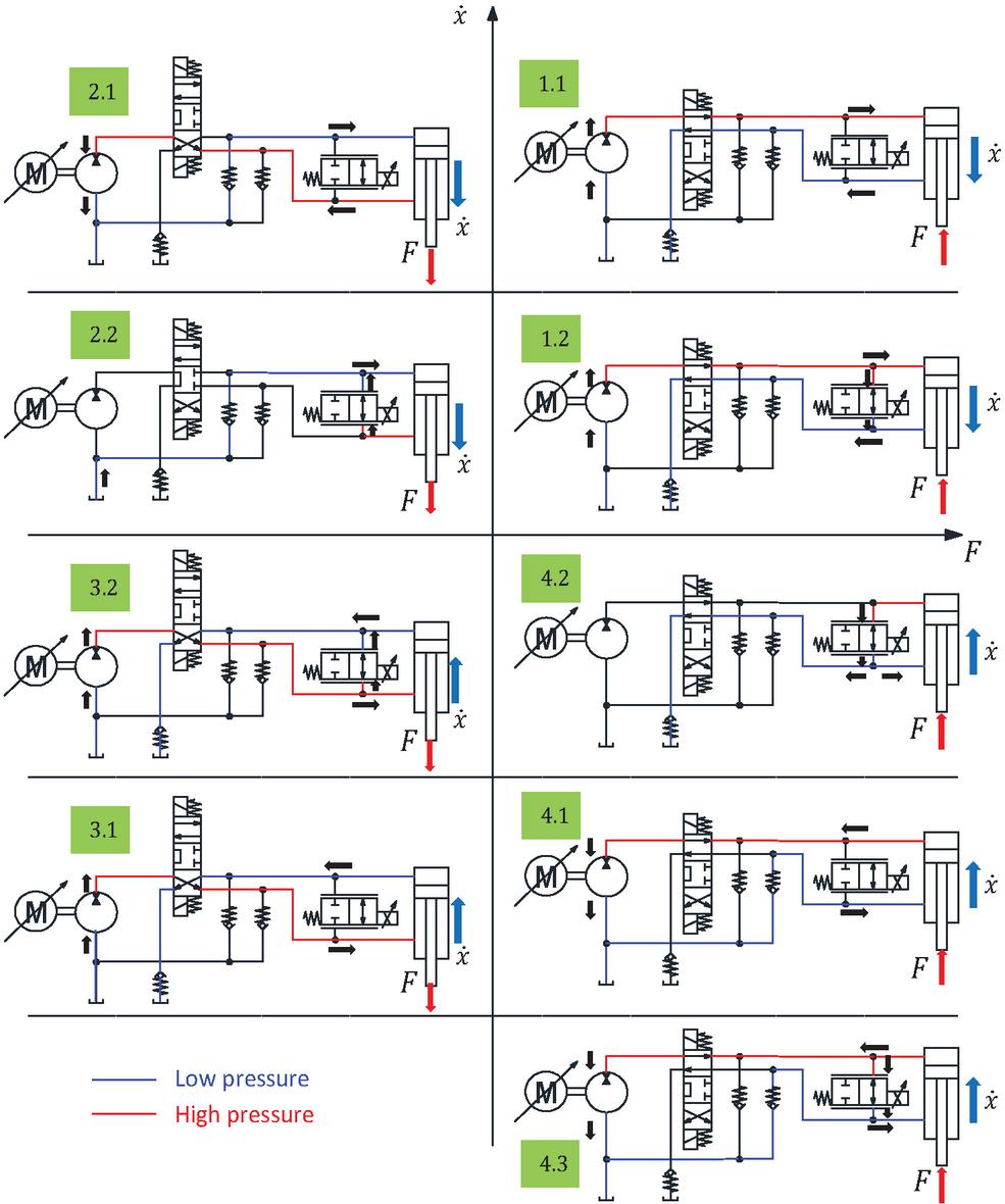
Figure 2 Functionality in four quadrants of the proposed system.
Due to the differential area of the single-rod CYL, the working modes are not structured symmetrically. With the same working principle, sub-mode 2.2 needs flow from the reservoir, while in sub-mode 4.2, extra flow is returned to the reservoir. Accordingly, a third sub-mode (4.3) is given. This scenario shows the fast actuation in the assistive phase, which is like the floating function in some classical hydraulic systems. HP is set to maximum speed () to regenerate as much energy as possible, and BPV is opened to recycle the rest of the flow from CYL, thus enables operation with higher speeds than HP alone would allow. The speed regulation is summarized in Figure 3. Because of the differential area of the cylinder, without a speed regulation, the maximum actuation velocity varies according to different loading conditions (grey region). This phenomenon may result in problems on the speed control in mobile applications under complex working conditions. Therefore, the speed regulation is necessary by giving a suitable speed command in four quadrants. The target speed region is shown in the highlighted red rectangle in Figure 3. All working modes given in Figure 2 are shown in the corresponding speed region. The low-speed modes (green region) and fast retraction mode (yellow region) involving the bypass valve are highlighted, respectively. As given in Figure 3, the bypass valve not only allows the system to cover the low-speed region with a fixed-displacement pump, also allows a faster actuation than the pump can achieve (sub-mode 4.3).
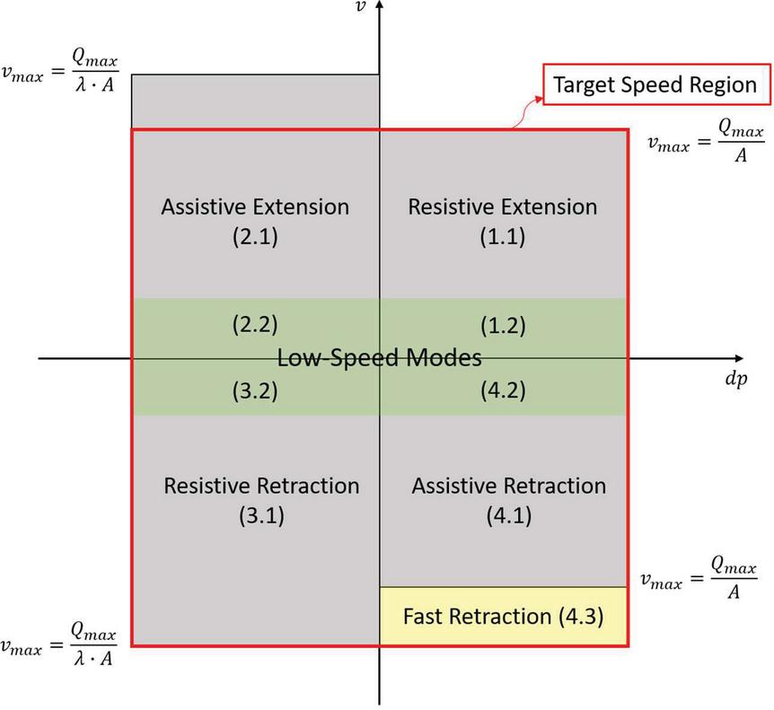
Figure 3 Speed regulation in four quadrants of the proposed system.
More details to classify the speed control in all sub-modes are given in Table 1, where is the speed command of HP and EM, between 1 and 1.
Table 1 Working modes classification
2.3 The Logic for Mode Switching
Focusing on switching among different modes, Figure 4 gives an example for the case of constant load direction (first and fourth quadrants in Figure 2).
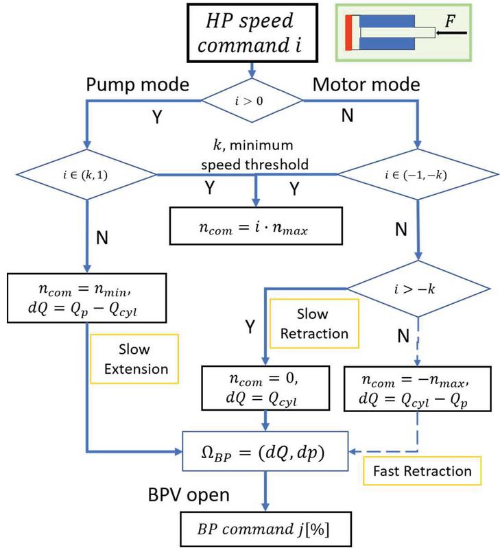
Figure 4 The logic for switching modes.
To start, a certain speed command is given and converted to the speed of HP as well as control current for BPV. The sign of indicates pumping modes for resistive loads and motoring modes for assistive loads. A speed threshold represents the boundary between sub-modes 1 and 2. A command with an absolute value less than results in the second sub-modes explained in Figure 2. In the slow actuation scenario, the flow rate going through BPV () is calculated by the difference between the desired flow rates from CYL and HP. The pressure difference across BPV () is measured to detect the load direction. The opening of BPV is controlled by command and defined by the valve characteristics. The used valve shows a linear relationship between flow and control command without pressure influence for the significant application conditions.
3 Simulation Model
3.1 Model Development
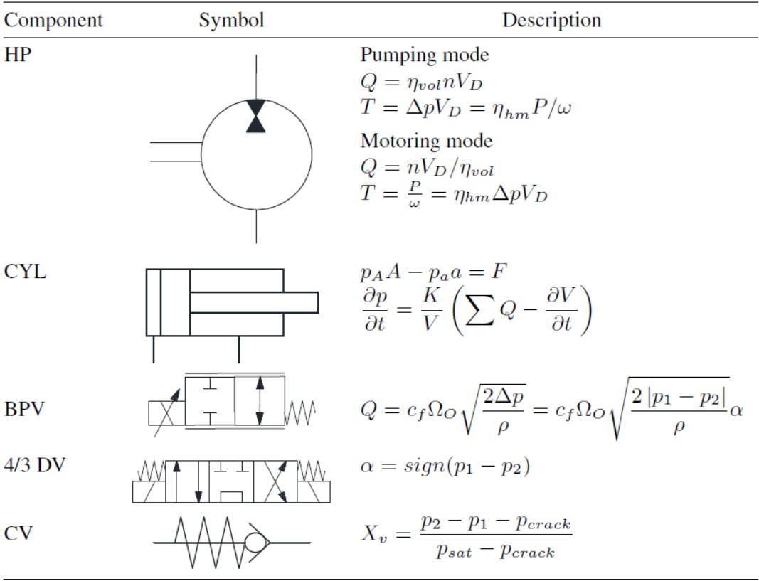
Based on the proposed system configuration in Figure 1, a lumped-parameter model is developed in Simcenter Amesim (Siemens PLM Software) for simulation. With the goal to validate the functionality of the proposed system, all hydraulic components are modeled with basic theoretical equations as outlined in Table 2.
Table 2 Modeling of components in the simulation
The parameters of the simulation are defined based on the datasheet of the hydraulic components. Figure 5 gives a graphical representation of the simulation model developed in Amesim environment. The flow curves of the directional valve and bypass valve are input to the model to reflect the throttle-less control.

Figure 5 Graphical representation of the lumped-parameter simulation model.
The main parameters of the simulation model are listed in Table 3. The volumetric efficiency of the hydraulic machine is ideally assumed as 100% for simplification.
3.2 Simulation Results
Validation for the 4-quadrant functionality of the proposed system was first conducted in steady-state simulation based on the architecture and parameters given above. Each time an input command is given and results in the velocity of actuation and a pump speed as outputs. All sub-modes detailed in Section 2 are covered in the simulation.
For a better understanding, the sign of data is defined as follows: HP speed is positive in pumping modes and negative in motoring modes. The velocity of actuation is positive when CYL extends, located in the upper area of the 4-quadrant map in Figure 2 (quadrants 1&2). Retraction is defined as negative. For the load applied on CYL, positive force results in a higher pressure in the piston chamber as given in the right area of Fig. 2 (quadrants 1&4). While the negative force is covered by quadrants 2&3, and the rod side of CYL sees the higher pressure. The maximum velocities of CYL extension and retraction, corresponding to the input commands 1 and 1, are defined by the velocities that can be reached in resistive phases, when HP works as a pump and reaches the maximum speed. Because of the differential area of CYL, the maximum retraction speed is higher than the maximum extension speed.
Table 3 Main parameters in the simulation
| Parameter | Value [unit] |
| Length of stroke | 0.8865[m] |
| Diameter of piston | 69.9[mm] |
| Diameter of rod | 44.2[mm] |
| Area ratio | 1.68 |
| Pump displacement | 16.5[cm3/rec] |
| Pump maximum speed | 3000[rpm] |
| Pump minimum speed | 500[rpm] |
| Crack pressure of CV | 0.35[bar] |
| Tank pressure | atmospheric pressure |
| Relief pressure | 210[bar] |
Simulation results with a constant positive load are shown in Figure 6.
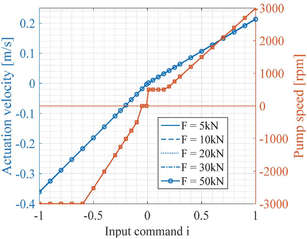
Figure 6 Simulation results with positive load (quadrant 1&4).
Although the speed performance of HP is nonlinear based on different sub-modes, the actuation velocity keeps linear. In the slow resistive extension phase, the pump speed remains at the minimum as defined in sub-mode 1.2. Slow assistive retraction results in a standstill of the pump, according to sub-mode 4.2. Energy recuperation cannot be achieved. In order to reach the maximum retraction speed, sub-mode 4.3 is activated when the input command gets closer to 1. Not much difference is observed with different loading conditions, at least not in this simplified lump-parameter model.
Similarly, simulation results with negative loads are given in Figure 7. In this case, CYL extension is assistive and retraction is resistive so that HP spins in the opposite direction compared to Figure 6. To match the same maximum velocity of the actuator, HP speed is controlled considering the area ratio of CYL, thus not reaching when the input command is 1. Slow actuation modes (sub-modes 2.2–3.2) work as expected.
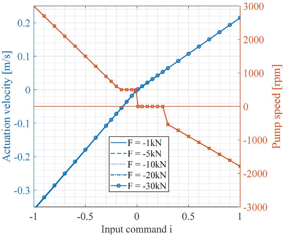
Figure 7 Simulation results with negative load (quadrant 2&3).
Focusing on the low-speed modes, a comparison between two typical scenarios with kN load is represented in Figure 8. Both, actuation velocity and HP speed, are normalized in the plot, and the former follows the input command closely with a nonlinear HP speed. The CYL’s differential areas result in a different HP speed under the same actuation velocity compared to resistive operation, which can be observed clearly in Figure 8. A zoom-in of the graph represents the sub-modes with input command from 0.3 to 0.3.
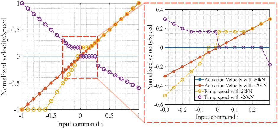
Figure 8 Comparison between two cases in the simulation.
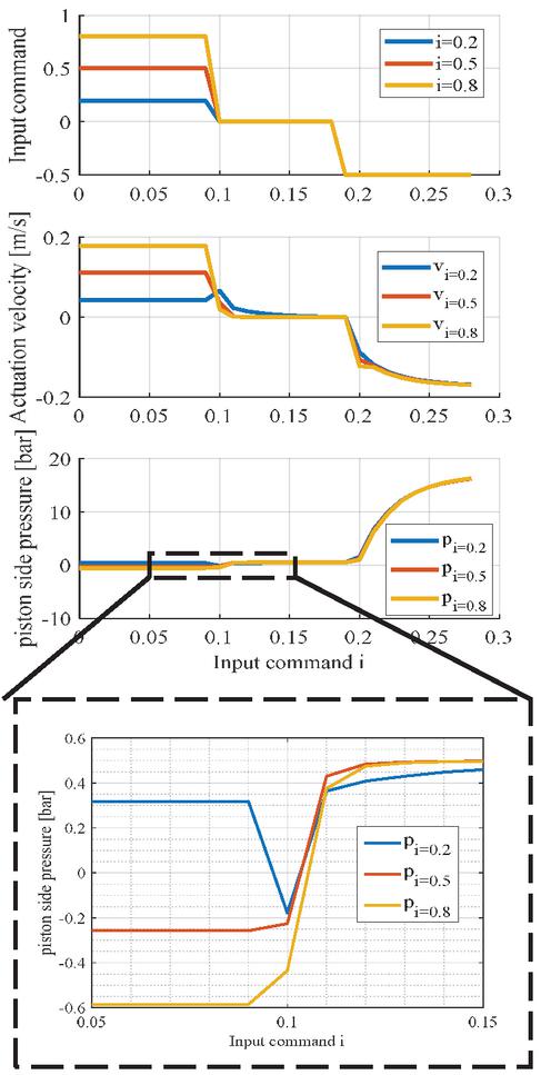
Figure 9 Cavitation in simulation results.
In addition, cavitation can be a major challenge of an open-circuit EHA, especially in quadrant 2 given in Figure 2. Under fast assistive retraction, a high flow rate is generated from the tank to the piston side of CYL, and cavitation is most likely to happen after CV1. To further investigate this issue, the simulation was conducted for working modes in quadrant 2, with initial input commands (0.2,0.5,0.8) representing slow, middle and high-speed extension. After some time of extension, zero commands are given to stop and then retract with the same command 0.5. The results are given in Figure 9.
The first plot shows the input command, the second shows the actuation velocity and the third represents the pressure in the piston-side chamber of CYL. A zoom-in of the third plot clearly shows that cavitation happens in a steady-state, where the pressure drops below zero except for the slow extension. Once a stop command is given, the pressure goes back immediately. As the simulation model is simplified and may not reflect the impact of cavitation accurately, more attention should be paid during experiments. A higher actuation velocity requires more flow; thus, cavitation is more likely to happen.
4 Experiments
4.1 Experimental Setup
With the goal to verify the performance of the proposed system in this study, a test rig is developed at Maha Fluid Power Research Center, Purdue University, Lafayette, USA. The conceptual structure of the test rig is represented in Figure 10.
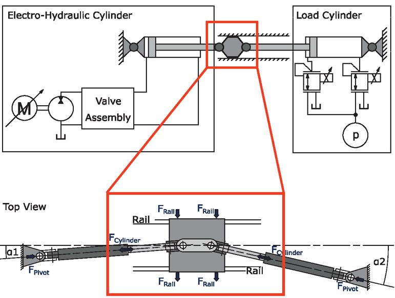
Figure 10 Conceptual schematic of the experimental setup.
The architecture of the test rig is based on two opposed cylinders: one cylinder is driven by the proposed EHA, the other one is used to apply the desired load on the EH drive. Two reducing-relieving valves are utilized on the load drive to adjust the pressure in both cylinder chambers continuously. The load force is then a result of the pressure forces acting against each other. Both cylinder drives are coupled with dual-axis joints to prevent damage due to misalignment. The linear ball rails compensate for potential side forces. The picture of the experimental setup in the authors’ lab is shown in Figure 11, and the hardware selected for the test rig is listed in Table 4.
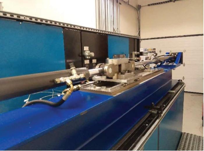
Figure 11 Picture of the test rig built in the lab.
Table 4 Hardware list in the experimental setup
| Hardware | Product Number |
| Gear pump/motor | Rexroth AZPF-12-016 RRR 20 ML |
| HDP servomotor | ABB VM47A00202001B00 |
| Inverter | ABB ACS800-U11 |
| 4/3 Directional valve | Rexroth WE10-5X-E |
| Prop. 2/2 direction valve | Rexroth VEP-5A-2Q-09 |
| Check valves | Rexroth VUCN-16A |
| Relief valves | Rexroth DBD1X |
| Filter | Rexroth RE51447 |
| Pressure sensor | Rexroth R917A10105 |
| Position sensor | ASM WS42 |
| Controller | NI cRio-9024 |
| Analog modules | NI9264 NI9205 NI9472 |
| Digital modules | NI9403 NI6421 |
4.2 Results from Experiments
To validate the functionality of the proposed system, as well as the simulation model previously described, the measurement results were compared to the simulations. With the same input command as for the simulation, actuation velocities were measured as given in Figure 12. Results given below are the average within a certain acquisition interval. In this way, the influence of noise on the signals is kept minimal.
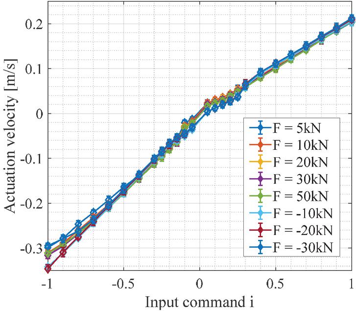
Figure 12 Measured actuation velocities under different loading condition.
It can be observed how the results of actuation velocities do not show the same behavior under different loading conditions, as the simulation does. On the other hand, good linearity can be noticed from the plots in Figure 12. The volumetric efficiency of the actual pump may vary based on different loading conditions, resulting in a small difference among the velocity plots for different loads. The performance of the low-speed modes shows some nonlinearity. This is because of the nonlinear characteristics of BPV in this region. Taking the pressure influence on the valve behavior into account, which is feasible as the pressures are measured anyway, the performance could be improved. This was not done before, because the pressure only has a significant influence on the valve behavior for very low-pressure drops, which are uncommon for many applications. Concerning the high-speed range when input commands are less than 0.8, the difference can be explained by slight cavitation in CYL.
A comparison between simulation and measurements is shown in Figure 13, including two typical cases with 20 kN load.
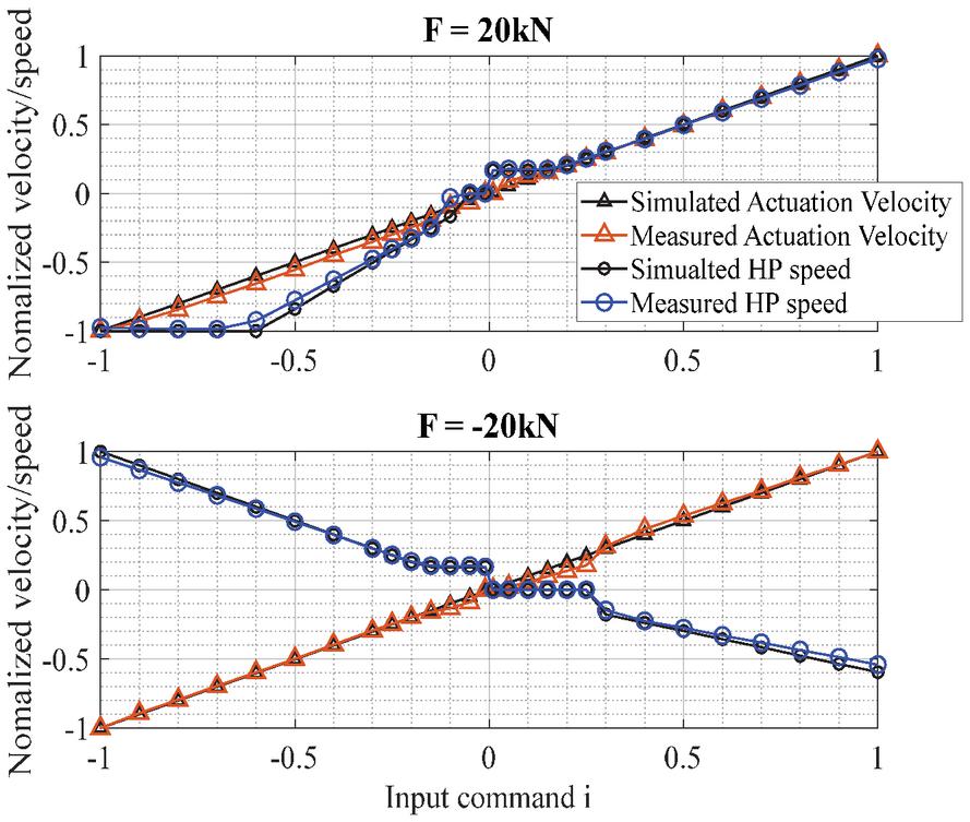
Figure 13 Comparison between simulation and measurements, kN.
The good match between experimental data and the simulation results confirms the validity of the simulation model. The results also confirm the functionality of the proposed open-circuit EHA. The small difference between simulation and measurements may result from measuring errors and noise.
An additional investigation was performed on transient load conditions. In this scenario, the input command stays the same, but the forces on the actuator suddenly change, the variation is such that the load switches from assistive (or overrunning) to resistive. This condition is realistic for several off-road applications. For example, the boom of an excavator works in an assistive case when lowering, but when the operator commands a dig into the ground, a load transition occurs from assistive to resistive. Measurements for this case are represented in Figure 14.
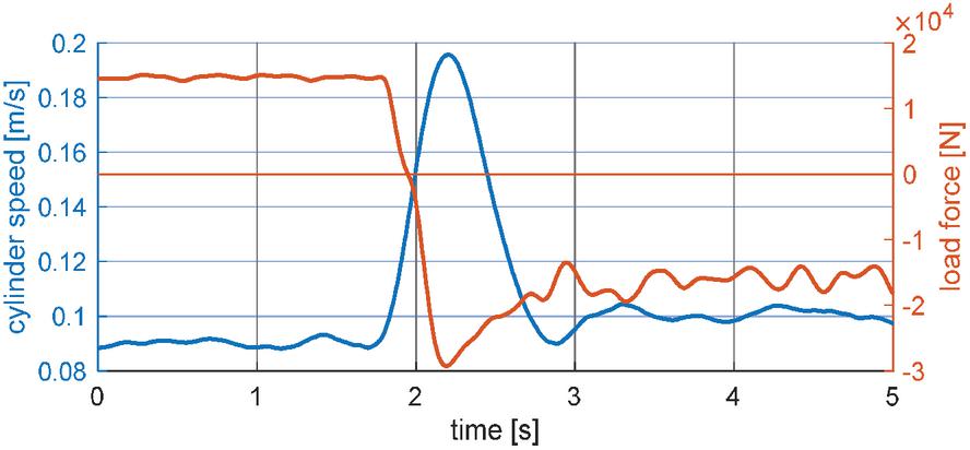
Figure 14 Load transition: from sub-modes 1.1 to 2.1.
A rapid change of actuation velocity can be observed, with acceleration around . This scenario is caused by the response and switching time of the 4/3 DV.
Before DV switches to the desired position, there is a short period when the system stays at sub-mode 1.1, but with a negative force, resulting in a faster extension than expected. However, after about one second, the system gets back to a steady-state and the actuation velocity returns to the same level. Depending on the applications, the acceleration within one second might still be acceptable.
For the opposite case, a load transition from sub-modes 2.1 (assistive extension) to 1.1 (resistive extension) was tested as shown in Figure 15. Starting from the assistive extension, cavitation may happen with high actuation velocity, as explained in Section 3, and results in a different performance. Even the 4/3 DV is fully opened in all working modes, the pressure drop is still noticeable at about 6 bar with the maximum flow rate of 75 L/min according to the flow curve given in Figure 5.
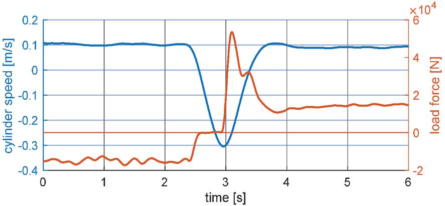
Figure 15 Load transition: from sub-modes 2.1 to 1.1.
According to the measurements, the actuation velocity changes from positive to negative, in less than one second, and changes back to the desired speed. Though the extension is expected, during the switching time, a fast retraction happens. The results can be explained by aeration or cavitation. During assistive extension, a void is formed in the piston chamber of CYL, so that CYL tends to retract and compress the air inside when the load direction changes. After the air bubbles are completely compressed or dissolved, the system works as expected again. This phenomenon may cause some issues in applications. A pressurized reservoir can be a good solution to avoid these phenomena. More experiments need to be done to validate possible solutions.
5 Conclusion and Outlook
A novel open-circuit EHA architecture, with the capability to regenerate energy in assistive phases and cover the full speed range, is presented in this paper. Validation of the four-quadrant functionality and performance verification of the proposed EHA system was conducted by both numerical and experimental methods. Addressing the challenge to achieve low-speed actuation of EHA, BPV is utilized under certain working modes with proper control logic. Based on the system configuration, a test rig was built at the authors’ research lab. Measurements show robust performance in a steady state for all defined working modes. The good match between simulation and experimental results confirms the potential to apply the proposed EHA further for commercial scenarios.
For future work, challenges of cavitation and dynamic response were noticed in the study, and more research can be conducted on these topics. Also, the control of the proposed EHA system involves the electric machine and the solenoid valves, so it is significant to develop an integrated controller and study the performance for mobile applications. Moreover, the energy-saving capability, which attracts much attention for the EHA architecture, can be studied further with a baseline analysis. Besides, research based on long-term thermal tests might be necessary to validate the self-sustainability of the proposed EHA, with the purpose to enable a technical realization and commercial applications with high-power levels.
Acknowledgment
The authors wish to thank Simcenter Amesim for the use of the simulation software, and Bosch Rexroth, Case New Holland Industrial for their support and for providing hardware that was used for the experiments. The project was supported by the Department of Energy, USA (DOE project DE-EE0008334, ‘Individual Electro-Hydraulic Drives for Off-Road Vehicles’).
Nomenclature
| Force [N] | |
| Velocity [m/s] | |
| Flow rate [L/min] | |
| Power [W] | |
| Area [] | |
| Area ratio | |
| Pressure [bar] | |
| Pressure difference [bar] | |
| Efficiency | |
| Torque [Nm] | |
| Speed [rpm] | |
| Angle speed [rad/s] | |
| Flow coefficient | |
| Effective bulk modulus [Pa] | |
| Speed command | |
| Volume [] | |
| Displacement [cc/rec] | |
| Open Area [] | |
| Density [] | |
| Fractional valve opening | |
| Subscripts | |
| vol | Volumetric |
| hm | Hydro-mechanical |
| 1,2 | Port 1,2 of components |
| max | Maximum |
| cyl | Cylinder side |
| Abbreviation | |
| EHA | Electro-hydraulic actuator |
| EHU | Electro-hydraulic unit |
| VM | Variable speed motor |
| CM | Constant speed motor |
| FP | Fixed displacement pump |
| VP | Variable displacement pump |
| CYL | Cylinder |
| BPV | Bypass valve |
| EM | Electric motor |
| HP | Hydraulic pump |
| DV | Directional valve |
References
[1] A. Vacca, “Energy efficiency and controllability of fluid power systems,” Energies, vol. 11, no. 5, 2018.
[2] L. Love, E. Lanke, and P. Alles, Estimating the Impact (Energy, Emissions and Economics) of the US Fluid Power Industry, no. December. 2012.
[3] D. B. Beck, D. E. Fischer, D. G. Kolks, D. J. Lübbert, D. S. Michel, and D. M. Schneider, “Novel System Architectures by Individual Drives,” 10th Int. Fluid Power Conf., pp. 29–62, 2016.
[4] Z. Quan, L. Quan, and J. Zhang, “Review of energy efficient direct pump controlled cylinder electro-hydraulic technology,” Renew. Sustain. Energy Rev., vol. 35, pp. 336–346, 2014.
[5] H. Liu, Y. Jiang, and S. Li, “Design and downhill speed control of an electric-hydrostatic hydraulic hybrid powertrain in battery-powered rail vehicles,” Energy, vol. 187, p. 115957, 2019.
[6] R. Navarro, “Performance of an electro-hydrostatic actuator on the F-18 systems research aircraft,” NASA Tech. Memo., no. 206224, 1997.
[7] S. Frischemeier, “Electrohydrostatic actuators for aircraft primary flight control-types, modelling and evaluation,” Proc. Fifth Scand. …, pp. 1–16, 1997.
[8] J. P. Henderson, A. Plummer, and N. Johnston, “An electro-hydrostatic actuator for hybrid active-passive vibration isolation,” Int. J. Hydromechatronics, vol. 1, no. 1, p. 47, 2018.
[9] G. Altare and A. Vacca, “A Design Solution for Efficient and Compact Electro- hydraulic Actuators,” Procedia Eng., vol. 106, pp. 8–16, 2015.
[10] S. Alfayad, F. B. Ouezdou, F. Namoun, and G. Gheng, “High performance integrated electro-hydraulic actuator for robotics – Part I: Principle, prototype design and first experiments,” Sensors Actuators, A Phys., vol. 169, no. 1, pp. 115–123, 2011.
[11] T. Yu, A. Plummer, P. Iravani, J. Bhatti, S. Zahedi Obe, and D. Moser, “Testing an Electrohydrostatic Powered Ankle Prosthesis with Transtibial and Transfemoral Amputees,” IFAC-PapersOnLine, vol. 49, no. 21, pp. 185–191, 2016.
[12] T. Lin, Q. Chen, H. Ren, W. Huang, Q. Chen, and S. Fu, “Review of boom potential energy regeneration technology for hydraulic construction machinery,” Renew. Sustain. Energy Rev., vol. 79, no. July 2016, pp. 358–371, 2017.
[13] S. Hui, Y. Lifu, and J. Junqing, “Hydraulic/electric synergy system (HESS) design for heavy hybrid vehicles,” Energy, vol. 35, no. 12, pp. 5328–5335, 2010.
[14] W. Zhao, X. Zhou, C. Wang, and Z. Luan, “Energy analysis and optimization design of vehicle electro-hydraulic compound steering system,” Appl. Energy, vol. 255, no. July, p. 113713, 2019.
[15] Parker, “Compact EHA Electro-Hydraulic Actuators for high power density applications.” Catalog HY22-3101E 9/20.
[16] T. B. Sweeney and M. C. Royer, “(12) Patent Application Publication (10) Pub. No.: US 2012/0067035 A1,” 2012.
[17] T. Pietrzyk, D. Roth, K. Schmitz, and G. Jacobs, “Design study of a high speed power unit for electro hydraulic actuators (EHA),” 11. Int. Fluid Konf., no. Dc, 2018.
[18] D. Padovani, S. Ketelsen, D. Hagen, and L. Schmidt, “A self-contained electro- hydraulic cylinder with passive load-holding capability,” Energies, vol. 12, no. 2, pp. 1–19, 2019.
[19] L. Schmidt, S. Ketelsen, M. H. Brask, and K. A. Mortensen, “A class of energy efficient self-contained electro-hydraulic drives with self-locking capability,” Energies, vol. 12, no. 10, pp. 1–27, 2019.
[20] L. Ge, L. Quan, Y. Li, X. Zhang, and J. Yang, “A novel hydraulic excavator boom driving system with high efficiency and potential energy regeneration capability,” Energy Convers. Manag., vol. 166, no. April, pp. 308–317, 2018.
[21] T. Lin and Q. Wang, “Hydraulic accumulator-motor-generator energy regeneration system for a hybrid hydraulic excavator,” Chinese J. Mech. Eng. (English Ed.), vol. 25, no. 6, pp. 1121–1129, 2012.
[22] S. Ketelsen, D. Padovani, T. O. Andersen, M. K. Ebbesen, and L. Schmidt, “Classification and review of pump-controlled differential cylinder drives,” Energies, vol. 12, no. 7, pp. 1–26, 2019.
[23] H. Liu, X. Zhang, L. Quan, and H. Zhang, “Research on energy consumption of injection molding machine driven by five different types of electro-hydraulic power units,” J. Clean. Prod., vol. 242, p. 118355, 2020.
[24] S. Qu, D. Fassbender, A. Vacca, B. Enrique, and U. Neumann, “A Closed Circuit Electro-Hydraulic Actuator With Energy Recuperation Capability,” 12th Int. Fluid Power Conf., pp. 89–98, 2020.
[25] K. Heybroek, J.-O. Palmberg, J. Lillemets, M. Lugnberg, and M. Ousbäck, “Evaluating a Pump Controlled Open Circuit Solution,” Proc. Int. Expo. Power Transm. IFPE’08, no. 24, pp. 681–694, 2008.
Biographies

Shaoyang Qu is a Ph.D. student in the School of Mechanical Engineering at Purdue University since Fall 2018. He attended Tsinghua University in Beijing, China, where he received his B.E. in Mechanical Engineering and B.S. in Business administration in 2018. Currently he is a research assistant in the Maha Fluid Power Research Center. His research interests focus on the electrification of the mobile hydraulic applications, including design and control of hydraulic systems and hybrid systems such as electro-hydraulic actuators.

David Fassbender received the Diploma degree in mechanical engineering from Technische Universität Dresden (TUD) in 2020. He is currently pursuing the Ph.D. degree in Automation Science and Engineering at Tampere University and in cooperation with Bosch Rexroth. From 2017 to 2018, he was a student research assistant with the Institute of Fluid Power at TUD, and in 2019, he stayed for eight months at Purdue University’s Maha Fluid Power Research Center as a visiting scholar. His research interest includes hydraulic systems design and control, heavy-duty mobile machinery as well as vehicle hybridization.

Andrea Vacca is a the Maha Fluid Power Faculty Chair and a Professor at Purdue University. He currently leads the Maha Fluid Power Research Center which was established in 2004 by the late Prof. Monika Ivantysynova.
Dr. Vacca completed his studies in Italy (Ph.D. from the University of Florence in 2005) and he joined Purdue University in 2010 after being an Assistant Professor at the University of Parma (Italy). Fluid power technology has been Dr. Vacca’s major research interest since 2002. Dr. Vacca authored the textbook “Hydraulic Fluid Power” by Wiley and more than 150 technical papers, most of them published in international journals or referred conferences. He is chair of Fluid Power Systems and Technology Division (FPST) of the American Society of Mechanical Engineers (ASME), and a former chair of the Fluid Power Division of the Society of Automotive Engineers (SAE). Dr. Vacca is also one of the Directors of the Global Fluid Power Society (GFPS). Furthermore, he is also the Editor in Chief of the International Journal of Fluid Power. Dr. Vacca also received the 2019 J. Braham medal of the Institution of the Mechanical Engineers (IMechE).

Enrique Busquets is the North American engineering director at Bosch Rexroth with prior leadership experience on engineering systems and software development. His current responsibility includes the development and commercialization of products for the off-highway market with emphasis on electronics, electrification, connectivity and automation. He is as well responsible for the North American test center comprising component testing, vehicle integration lab and proving grounds. He holds an M.S. and Ph.D. in engineering from Purdue University.
International Journal of Fluid Power, Vol. 22_2, 233–258.
doi: 10.13052/ijfp1439-9776.2224
© 2021 River Publishers