Force-based Active Compliance Control of Hydraulic Quadruped Robot
Zhu Rui1,*, Yang Qingjun1, Chen Chen2, Jiang Chunli1, Li Congfei1 and Wang Yuxuan1
1School of Mechatronics Engineering, Harbin Institute of Technology, Harbin, China
2Shenyang Aircraft Design&Research, Shenyang, China
E-mail: 354732175@qq.com
*Corresponding Author
Received 13 November 2020; Accepted 28 January 2021; Publication 26 May 2021
Abstract
The hydraulically driven quadruped robot has received extensive attention from many scholars due to its high power density and adaptability to unstructured terrain. However, the research on hydraulic quadruped robots based on torque control is not mature enough, especially in the aspect of multi-rigid body dynamics. In this paper, the most commonly used gait trot is selected as the research object. First, the multi-rigid motion equation of the quadruped robot is established by the spin recursion method based on Lie groups. Next, the Lagrange multiplier is used to represent the constraint force to establish the 12-degree-of-freedom inverse dynamics model of the quadruped robot’s stance phase. And the hybrid dynamics method is used to reduce the dimension of the inversion matrix, which simplifies the solution process of the dynamics model. Then, the trajectory of the foot is planned. Through the analysis of the simplified model, it is concluded that the gait cycle and the initial position of the stance phase are important factors affecting the stability of the trot gait. Finally, the controller framework of the quadruped robot is introduced, and the effectiveness of the algorithm designed in this paper is verified through the co-simulation of the trot gait. The co-simulation results show that the inverse dynamics algorithm can be used as the feedforward of the control system, which can greatly reduce the gains of the PD controller; the robot has good compliance and can achieve stable trotting.
Keywords: Hydraulic quadruped robot, compliance control, multi-rigid body dynamics, hybrid dynamics, co-simulation.
1 Introduction
After decades of development, robots can replace humans to complete some tasks, such as rescue and disaster relief, and investigation. Compared to wheeled robots and crawler robots, quadruped robots are valued by scientific research institutions in various countries because of their ability to adapt to unstructured terrain. According to the classification of driving methods, quadruped robots can be divided into electric motor driving and hydraulic driving. Because hydraulic driving has the characteristics of high energy density, fast response speed and strong load capacity, it has attracted wider attention. In recent years, many hydraulic quadruped robots have appeared, among which Bigdog is the most representative [1, 2]. Bigdog can complete difficult movements and resist lateral interference, but the relevant organization has not disclosed its structural design and related control algorithm.
Historically, robotic arms and legged robots have mostly adopted position control methods. Because the contact dynamics are difficult to fully consider in the position control system, the interaction between the robot and the environment needs to be carefully considered in the kinematic space. Although position-controlled robots can already complete some specific tasks, for legged robots, when facing unstructured terrain, non-smooth contact dynamics and unavoidable impacts will cause the robot to lose balance. When the robot interacts with the environment, controlling the torque of the robot joints and the contact force between the robot and the environment is crucial. Therefore, force-controlled robots are more in line with our needs. Hogan calls this robot-environment interaction impedance control [3]. Impedance control is a typical active compliance control, which can be divided into force-based and position-based. For humans, research shows that when humans interact with the environment, the antagonistic action of muscles can control the torque of joints, which is equivalent to active compliance control [4, 5]. However, active compliance control has a delay of tens of milliseconds [6], which requires certain elastic elements to protect the actuator system during the delay, e.g. human skin soft tissue and tendons, which is called passive compliance control. Therefore, the existence of active compliance control and passive compliance control is a prerequisite for the ideal interaction between the robot and the environment. In this paper, inverse kinematics feedforward link and PD controller are used as active compliance control modules, and the mechanical spring damping of the calf of the robot is used as passive compliance control module.
In recent years, research on quadruped robots based on force-based compliance control can be divided into two aspects. One aspect is the research of series elastic actuator (SEA), that is, elastic elements and actuators are connected in series, which can fully play the role of passive compliance. Most motor-controlled quadruped robots use SEA, such as StarlETH [7, 8]; the other aspect is the research of active compliance control strategies, such as hydraulic quadruped robot HyQ [9, 10]. For hydraulic quadruped robots, due to the rigidity of hydraulic transmission, SEA will greatly reduce the bandwidth of the actuator [9], so we no longer consider SEA. For force-based active compliance control, there are two control strategies, namely virtual model control and Inverse dynamics feedforward combined with PD control. Most of the quadruped robots use the former [11, 12], but this method ignores the dynamics characteristics of rigid bodies, and a set of determined controller gains and weights can only be used in a specific situation [8], which is not conducive to the robot’s adaptation to different environments; the inverse dynamics model takes into account the inertia parameters of the various components of the body, and it is easier to accurately calculate the driving torque of the joint and the contact force at the foot. Only [10] mentioned this method in the field of hydraulic quadruped robots, but did not explain how to efficiently build a multi-rigid body dynamics model of a quadruped robot and improve its solution efficiency. This is also the problem addressed in this paper.
The trajectory of the foot and the selection of gait parameters are very important for the stable motion of the robot. In terms of trajectory planning of quadruped robots, central pattern generators (CPG) is the most widely known [17–19]. Related researchers use nonlinear oscillators to synthesize foot trajectories. However, it is difficult for CPG to incorporate online feedback, which is not conducive to further improving the robot’s motion ability [20]. Barkan U proposed an analytical trajectory generation based on the zero moment point (ZMP) to realize the trot gait of HyQ, but in order to ensure that the ZMP is in the support area, the duty cycle of the trot gait is greater than 0.5 [20]. The trajectory generation designed in this paper can be used for trot gait with a duty cycle less than or equal to 0.5. Through the analysis of the simplified model, the key gait parameters that affect the stability of the trot are found, and the stable trot of the robot is realized without being restricted to the ZMP method.
The contributions of this article have two aspects: the main contribution is to efficiently establish the multi-rigid body dynamics model of the quadruped robot, and combine the Lagrange multiplier method and the hybrid dynamics method to reduce the amount of calculation. The designed inverse dynamics algorithm is used as the feedforward of the controller, which greatly reduces the gains of the PD controller and realizes the active compliance of the robot. On the other hand, through theoretical analysis, it is concluded that the gait cycle and the initial state of the stance phase are the key factors affecting dynamic stability. The proposed trajectory generator can realize the stable trot of the robot.
This paper is divided into 6 parts: in Section 2, the forward and inverse kinematics of the quadruped robot are analyzed, and the multi-rigid body dynamic equation of the quadruped robot is established by using the spin recursion method based on Lie groups and algebras. In Section 3, a 12-degree-of-freedom inverse dynamics model of the robot is established. The hybrid dynamics method is used to reduce the dimension of the inverse matrix and simplify the solution process. The gait generator is introduced in the Section 4. In Section 5, the proposed inverse dynamics algorithm is used as the feedforward of the force controller. And the effectiveness of the related algorithm is verified by co-simulation. Section 6 summarizes the paper and proposes future research plans.
2 Multi-rigid Kinematics and Inverse Dynamics Analysis of the Quadruped Robot
2.1 Kinematics Analysis Based on Floating Body
In [13], we made a detailed discussion of the robot single-leg system, established a robot single-leg kinematics and dynamics model, and optimized the single-leg structure by analyzing the natural frequency. But for quadruped robot movement, the inertia parameters of the trunk are very important, so the influence of the trunk cannot be ignored. Featherstone defines floating body as follows [14]: there is no constraint between the centroid and the inertial coordinate system, and there is no corresponding drive, which means that the body has 6-degree-of-freedom relative to the inertial coordinate system; for a quadruped robot, its trunk is a floating body. According to [14], a virtual 6-degree-of-freedom joint can be used to connect the inertial system to the trunk. The structure of the four legs of the robot are completely the same, namely the left front leg (LF), right front leg (RF), left hind leg (LH), right hind leg (RH), and the specific structural parameters and configuration method of the legs refer to [13]. To facilitate the kinematics analysis, we assume that the legs in the stance phase are strictly in contact with the ground without sliding, and a simple model as shown in Figure 1 is established.

Figure 1 Kinematics model of our quadruped robot. M is the inertial coordinate system, N is the body coordinate system of the trunk, and M and N are connected by a virtual 6-degree-of-freedom joint. Points A to D are the hinge point and end point of the RF leg. , , are the angles of the joints, and l, l, l are the dimensions of the connecting rods.
According to the geometric relationship shown in Figure 1, we can have
| (1) |
According to the joints rotation angles and the dimensions of the connecting rods, equation (1) can be obtained from positive kinematics
| (2) |
In the inertial coordinate system, the position of N and D can be recorded as and . In the body coordinate system, the position of hinge point A can be recorded as . Then, we can get
| (3) |
Accurately obtaining the inverse kinematics solution is an indispensable part of inverse dynamics modeling. For trajectory planning, we always think that r and r are definite, and then we can get the inverse kinematics solution according to Equation (2.1). Let the left side of Equation (2.1) be , and the inverse solution is
| (4) |
where .
2.2 Inverse Dynamics Analysis of the Robot
The quadruped robot is a multi-rigid body dynamics system with a floating body. After considering the virtual 6-degree-of-freedom of the floating trunk, there are 18 degrees of freedom. The swing leg needs to reach the planned foothold accurately, and the swing leg in the air does not interact with the environment. According to the method in [8], we adopt the position control strategy for the swing leg; the stance leg interacts with the environment while supporting the body movement so the force control strategy is adopted for the stance leg. Because the stance legs and the trunk occupy most of the mass of the robot, the 2 legs in the swing phase can be ignored. In this way, the degrees of freedom have become 12, which are 6 virtual degrees of freedom of the trunk and 6 active degrees of freedom of the 2 stance legs.
Due to the existence of floating body and too many degrees of freedom in the system, the traditional Lagrange equation, Rolls equation, etc. are more troublesome to use, which will bring a large amount of calculation and is not conducive to programming. In the case of a large number of degrees of freedom, Newton Euler’s recursion method is usually used to establish the dynamics equations of the system, but Newton’s Euler equation are expressed using 3D vectors, which is still more complicated [14]. Featherstone [14] and Kevin [15] used 6D vectors to analyze the kinematics and dynamics of multi-rigid-body systems, that is, the recursive dynamics of spins based on Lie groups and algebras. Compared with the 3D vector, the 6D vector representation greatly reduces the number of algebras and makes it easier to efficiently obtain the system’s equations of motion. The derivation process of the inverse dynamics equations in this paper is under the system of [14]. To facilitate the derivation, we build a simple model as shown in Figure 2.

Figure 2 Dynamics model of our quadruped robot. M is the inertial coordinate system, The black coordinate system represents the joint coordinate system, and the green coordinate system represents the rigid body centroid coordinate system; represents the robot geometric parameters; represents the 6 generalized coordinates of the trunk; represents the generalized coordinates of the 2 stance legs; and represent the mass and inertia tensor of each component; According to the definition in [15], is called screw axes. Using the representation method in the joint coordinate system can reduce the calculation amount [14], at this time, . The trunk is connected to the inertial coordinate system through a virtual 6-degree-of-freedom joint, i.e. .
The most important parameters in the dynamics equations are the mass and inertia tensor. Because the recursive calculation is performed in the joint coordinate system, the rotation matrix is used to transform the inertia tensor into the joint coordinate system: , and . The spatial inertia tensor is used to represent the mass and inertia tensor of the rigid body
| (5) |
where [r] is the antisymmetric matrix of the position vectors of the two coordinate systems.
According to [14], we can get the following inverse dynamics recursive expressions
| (6) | |
| (7) | |
| (8) | |
| (9) | |
| (10) | |
| (11) |
where V represents the velocity spin of the joint; (i) is the parent of the rigid body i; represents the coordinate transformation matrix, which is a 6 6 matrix; V is the velocity spin of the rigid body; a is the acceleration spin of the rigid body; f is the net force acting on the rigid body; (i) represents the children of rigid body i; f represents joint force; represents the generalized force to be applied; and are spatial velocity cross operators.
For a fixed base robot, can be directly used as the feedforward link of a force controller. However, the quadruped robot trunk in the stance phase is a floating body, and cannot be used directly.
3 Inverse Dynamics Algorithm of the Quadruped Robot Based on a Floating Body
According to the composite rigid body dynamics [14], we can easily obtain the dynamics equation of the quadruped robot without constraints according to Equations (6) to (11)
| (12) |
The trunk of the quadruped robot is a floating body with 6 degree-of-freedom. These virtual degrees of freedom are not driven. As an under-driven system, the Equation (12) cannot be used directly. But the 2 stance legs of the robot are in contact with the environment, and each leg can establish three constraints with the environment. As long as the constraints established by the 2 legs are linearly independent, the robot will no longer be under-driven. The left side of Equation (12) is unchanged; we can use the Lagrange multiplier method to establish dynamics equations with constraints
| (13) |
where is the inertia matrix; is the bias force matrix; is the joint selection matrix; is the vector of generalized forces; is the constrained Jacobian matrix, follow the leg configuration we defined earlier [13], J is full rank; is the vector of constraint forces.
We always assume that the foot of the stance leg is not moving relative to the ground, we will have
| (14) |
According to Equations (13) and (14), we can obtain
| (15) |
Inserting Equation (15) into (13) and multiplying both sides by (SHS)SH, we will have
| (16) |
where and .
As can be seen from the Equation (3), if is invertible, we can obtain the generalized forces, but in fact this approach is not desirable for two reasons. One is that this method is too computationally expensive, and the other is that is usually rank deficient and therefore not invertible.
If the sampling time is set sufficiently small, the constraint forces can be calculated using the joint torques at the previous moment, that is, at time t is obtained from at time , and the value of can be measured by the force sensor in real time [16]. In this way, we will have
| (17) |
In this case, we can consider of Equation (13) as an external forces vector and replace it with F. According to the derivation process of Equation (3), we will have
| (18) |
From Equation (18), we can get the generalized forces, but it still needs to invert the entire inertia matrix. This is the largest calculation in the entire algorithm, and it is easy to cause error amplification in practical application.
Featherstone introduces the hybrid dynamics method, which combines forward kinematics and inverse kinematics to solve the problem, it can make the problem simple [14]. Under the hybrid dynamics approach, we have
| (19) | ||
| (20) |
where and are acceleration and force variables related to forward dynamics, and and are acceleration and force variables related to inverse dynamics, at this point, Equation (12) becomes
| (21) |
Equation (21) has two unknown variables, and . Move these two unknown variables to the left side of the equation, and then we get
| (22) |
From Equation (22), we can obtain and ; this is the solution process of hybrid dynamics. For our inverse dynamics model, because has been regarded as an external forces vector F, there is no unknown constrained force so we can use the mixed dynamics method. Equation (13) can be written as
| (23) |
Further derivation gives
| (24) | |
| (25) | |
| (26) |
Compared with Equation (18), the number of matrix inversions in Equation (26) is reduced, and we no longer need to invert the entire inertia matrix, so we use Equation (26) as the feedforward term for our torque controller.
4 Analytical Trajectory Generation
Trajectory generation refers to determining the foot trajectory of the stance phase and the swing phase. The foot trajectory in the robot movement process includes two aspects: one is the pre-planned trajectory, such as the trajectory function of the foot in the horizontal direction; the other is the compensation of the foot trajectory, such as online adjustment of the trajectory according to the terrain estimation module. This paper mainly designs the pre-planned foot trajectory. The quadruped robot mainly moves in the sagittal plane. Take the RF leg as an example, its schematic diagram is shown in Figure 3. The relevant parameters are defined as follows: Oxz is the sagittal plane; T is the gait cycle, which represents the time it takes for a leg to complete a stance phase and swing phase; v represents the forward speed; s is the stride, and ; is the step height of the swing phase; represents the initial position of the stance phase.
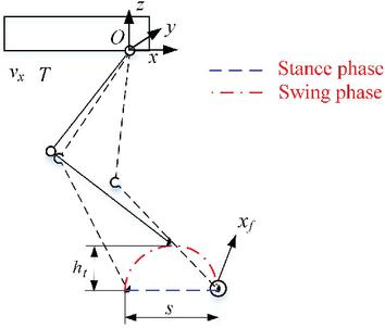
Figure 3 Schematic diagram of trajectory planning.
The time interval of one cycle of the robot is recorded as [0 T]. Assuming that the RF leg first starts to move in the stance phase, then the interval [0 T/2] is for stance phase, interval [T/2 T] is for swing phase. The stance phase does not move in the z direction so only the trajectory in the x direction needs to be considered. Considering to reduce the inertial force of the robot in the horizontal direction, the trajectory planning method of the stance phase in the x direction is a uniform linear motion, that is, the trajectory function of the stance phase is
| (27) |
where X represents the position of the foot of the RF leg relative to point O; .
For the swing phase, in order to ensure a smooth connection with the stance phase, the position, speed, and acceleration of the start and end states of the swing phase in the horizontal direction are required to be consistent with the beginning and end states of the stance phase. This paper adopts 5th-order interpolation polynomial, which can be described as
| (28) |
The initial conditions of each derivative can be described as
| (29) |
where ; .
According to Equations (28) and (29) to solve the linear equations, the trajectory in the x direction of the swing phase can be obtained as
| (30) |
where ; .
In order to avoid shock, the speed and acceleration of the start and end states of the swing phase in the z direction are zero. The trajectory in the z direction is a compound cycloid, which can be described as
| (31) |
where ; .
According to Equations (27) to (31), the foot trajectory curve shown in Figure 4 can be obtained, and the trajectory of the robot in the swing phase is smoothly connected with the stance phase.
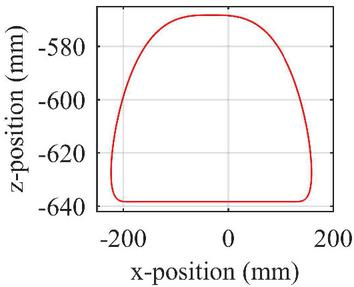
Figure 4 The foot trajectory curve.
Trot is a process that requires dynamic stability so the stability of the motion process needs to be analyzed. Take the movement of the robot in the sagittal plane as an example, a simplified schematic diagram is shown in Figure 5.
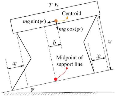
Figure 5 Schematic diagram of movement in the sagittal plane. is the inclination angle of the ground; The total mass of the robot is recorded as m; b is the distance between the midpoint of the support line and the center of mass; is the standing height of the robot.
When the robot adopts the trot gait, the projection of its center of mass will deviate from the support area so the robot will rotate around the midpoint of the support line during the movement. According to the angular momentum theorem, we can get
| (32) |
where J and are the moment of inertia and angular acceleration of the body. Integrating the angular acceleration twice, we can get the rotation angle of the body
| (33) |
It can be seen that the body cannot avoid rotation. In order to improve the stability of the robot movement process, it is hoped that the rotation angle of the body after a complete stance phase is equal to zero, that is, when , Equation (4) is equal to 0. Through calculation, we can get the following expression
| (34) |
Next, the extreme points of Equation (4) are analyzed. Take Equation (34) into (4) and find the first derivative, we can get
| (35) |
Let , then and . And when ; , . It can be concluded that when , the body has the maximum rotation angle, and the maximum rotation angle can be described as
| (36) |
For trot gait, To ensure that the body rotation angle equal to 0, should be determined according to Equation (34). On the other hand, in order to reduce the maximum rotation angle of the movement process, the value of the gait cycle T should be as small as possible.
5 Torque Control Framework and Co-simulation
5.1 Torque Control Framework
As shown in Figure 6, the torque controller is composed of an inner-loop HDU force control and an outer-loop active compliance control. The Hydraulic drive unit (HDU) is composed of hydraulic cylinder, servo valve, displacement sensor and force sensor (Figure 7). The trajectory planning module is the analytical trajectory generation designed in Section 4. The inverse kinematics module generates the desired joint angle displacement, velocity and angular acceleration according to the foot trajectory. The inverse dynamics module uses the inverse dynamics algorithm proposed in Section 3 to obtain the feedforward torque of the torque controller. The inner-loop force control uses PID and speed compensation control strategies, which can make the response speed and stability of the valve-controlled cylinder satisfactory [10]. The outer-loop uses the inverse dynamics module as the feedforward of the control system, and the PD controller as the torque compensation. The form of the PD controller is shown in Equation (37). On the premise that the position tracking performance meets the demand, the smaller the PD gains mean the better the compliance of the system. The outer-loop control is also equivalent to active compliance control. In addition, because our quadruped robot is driven by hydraulic cylinders, the linear displacement and force of the hydraulic cylinder need to be converted into angle and torque variables through geometric relationships.
| (37) |
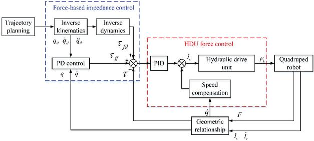
Figure 6 Torque control framework. is the feedforward value of inverse dynamics; is the compensation value of the PD controller; is the actual torque.
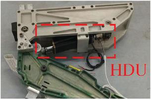
Figure 7 Hydraulic drive unit.
5.2 Co-simulation Framework
Adams is the world’s most widely used multibody dynamics simulation software, but it is tedious to implement complex control in it so we use Adams and Matlab-Simulink for co-simulation. The framework of co-simulation is shown in Figure 8. Through the trajectory planning, inverse kinematics and inverse dynamics modules in Matlab, the position and force signals are calculated and transmitted to the force controller and position controller, the controller generates the current control signal of the servo valve to control the flow of the hydraulic system, the hydraulic system simultaneously establishes hydraulic pressure based on the load in Adams; Adams receives the force signal calculated by Matlab to realize the movement of the virtual prototype, and feedbacks the position and attitude of the quadruped robot, the displacement and force of the hydraulic cylinder to Matlab; Matlab receives the signals fed back by Adams and sends them to the corresponding controller to realize the closed loop of the control system.
The 3D model in Adams was a virtual prototype of our quadruped robot, as shown in Figure 9. In order to make the simulation results of the virtual prototype as reliable as possible, we strictly defined a series of parameters in Adams; see Table 1 for specific parameters. As mentioned in the Section 1, it takes tens of milliseconds to implement active compliance control. Therefore, we installed a mechanical spring damper on the calf of the robot as a passive compliance control link; see Table 1 for spring stiffness and damping values.
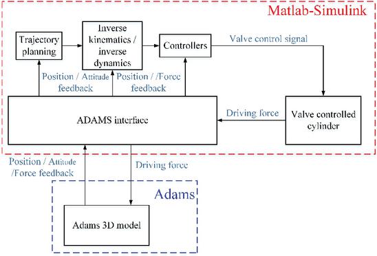
Figure 8 The framework of co-simulation.
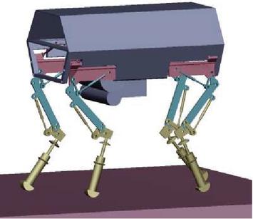
Figure 9 Quadruped robot virtual prototype in Adams.
Table 1 The parameters values of virtual prototype
| Parameter Name | Value | Unit |
| The length of the robot | 0.9 | m |
| The width of the robot | 0.44 | m |
| The length of the thigh | 0.34 | m |
| The length of the calf | 0.33 | m |
| The mass of the robot | 90 | kg |
| Moment of inertia of the trunk | diag[3.74,3.32,2.74] | kgm |
| The mass of the thigh | 2.8 | kg |
| Moment of inertia of the thigh | diag[0.035,0.034,0.013] | kgm |
| The mass of the calf | 1.75 | kg |
| Moment of inertia of the calf | diag[0.045,0.036,0.011] | kgm |
| Environmental stiffness | 2000 | N/mm |
| Environmental damping | 20 | Ns/mm |
| Coefficient of static friction | 0.8 | |
| Coefficient of dynamic friction | 0.75 | |
| Calf passive spring stiffness | 80 | N/mm |
| Calf passive damping coefficient | 6 | Ns/mm |
| Co-simulation sampling time | 0.0001 | s |
Table 2 Gait parameters of the quadruped robot
| Parameter Name | Value | unit |
| Gait cycle (T) | 0.8 | s |
| Duty cycle (d) | 0.5 | |
| Speed (v) | 800 | mm/s |
| Step height (h) | 70 | mm |
| Initial position (x) | s/3 | mm |
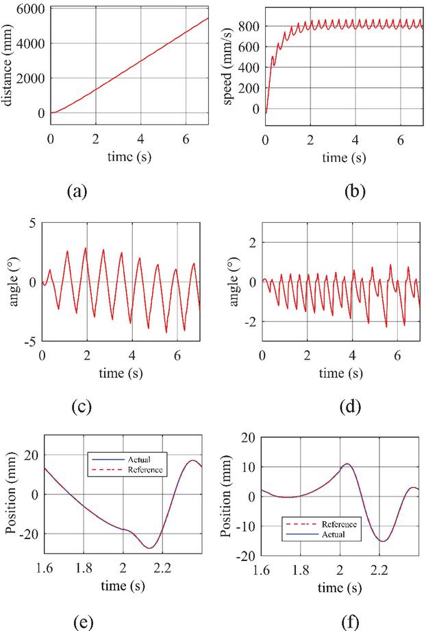
Figure 10 Simulation results of trot of the quadruped robot. (a) and (b) are the displacement and speed of the robot. (c) and (d) are roll angle and pitch angle respectively. (e) and (f) are the positions of the knee joint hydraulic cylinder and the hip joint hydraulic cylinder of the RF leg.
5.3 Simulation Results on Flat Ground
The inverse dynamics algorithm and the analytical trajectory generation were built in Simulink. The trot of the quadruped robot was selected as the simulation object. The inclination angle of the ground in the simulation was 0 degrees. The relevant gait parameter values are defined in Table 2. The simulation results are shown in Figure 10. It can be seen that after a brief acceleration, the robot can maintain a stable motion near the desired speed [Figure 10(a), (b)]. The fluctuations of the roll angle and pitch angle of the robot are within acceptable limit [Figure 10(c), (d)]. Under the combined action of inverse dynamics feedforward and PD control, the position tracking performance of the actuator is satisfactory [Figure 10(e), (f)]. As shown in the Figure 10(e) and (f), there is a slightly larger deviation between the actual hydraulic cylinder position and the expected hydraulic cylinder position near s, which is the manifestation of the low stiffness characteristics of the system. Because the swinging leg touches the ground to bring a certain impact, the active compliance of the system makes the actuator have a buffer effect.
As we mentioned earlier, under the premise of ensuring the position tracking performance, it is hoped that the gains of the PD controller is small enough. If the gains of the PD controller are set to a large value, it means that the stiffness of the system is large, which will cause the compliance of the system to deteriorate. In our simulation, k was equal to 500 Nm/rad and k was equal to 60 Nms/rad. The torque curves of the two joints of the RF leg are shown in Figure 11. It can be seen from Figure 11 that the feedforward torque calculated by the inverse dynamics module obviously occupies the dominant position of the torque controller.
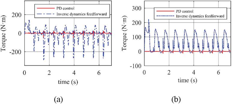
Figure 11 The torques of the joints of the RF leg during the simulation. (a) is the torque of the hip joint and (b) is the torque of the knee joint.

Figure 12 The influence of T and x on motion stability. (a) (c) are the simulation results where T is equal to different values. (e) (f) are the simulation results where x is equal to different values. (a) and (d) represent forward speed of the robot, (b) and (e) represent the roll angle, and (c) and (f) represent the pitch angle.
5.4 Gait Cycle and Initial Position of the Stance Phase
The influence of gait cycle T and initial position of the stance phase x on stability was verified by co-simulation. In the simulation process, the robot moved on a flat ground, the value range of T was 0.6 1 s, the value range of x was 0 120 mm, and the values of other parameters are the same as in Table 2. First, the influence of T was verified. During the simulation, x was always equal to 80 mm. The simulation results of different values of T are shown in Figure 12(a) (c). As T increases, the fluctuations of speed, roll angle and pitch angle all increase, so T has a significant impact on stability. The smaller the T, the more stable the robot movement. The simulation results are consistent with the conclusion of Equation (36). Therefore, in practical applications, a small T should be selected. Next, the influence of x was analyzed. During the simulation, T was always equal to 0.6 s. The simulation results of different values of x are shown in Figure 12(e) (f). It can be seen that when x is equal to 80 mm, which is equal to s/3, the fluctuations of the speed, roll angle and pitch angle are minimal. This is also consistent with the previous analysis results.
The above analysis shows that the influence of T and x on motion stability cannot be ignored. In order to make the robot move more stable, the value of T should be as small as possible, and x should be determined according to Equation (34).
5.5 Simulation Results on Rugged Ground
When the robot moves on rugged ground, its legs touch the ground in advance or step into a pit will bring impact. During the simulation, the ground was set to be uneven, T was equal to 0.6 s, and the values of other parameters are the same as in Table 2. The robot used position control (only PD control) and force-based active compliance control strategies to pass through the rugged ground respectively. The simulation results are shown in Figure 13. Compared with active compliance control, the roll angle and pitch angle fluctuations of the robot using the position control strategy are obviously larger.
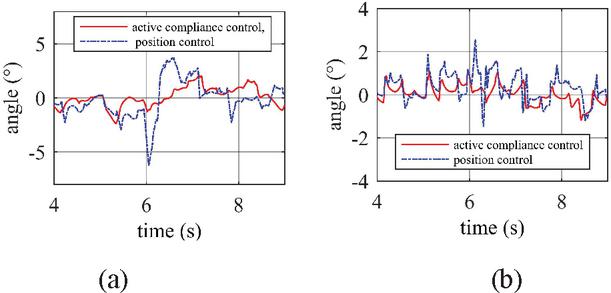
Figure 13 The roll and pitch angles of the robot when moving on rough ground. (a) is the roll angle and (b) is the pitch angle.
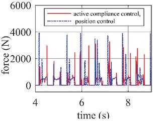
Figure 14 The impact force of the foot.
Further, the foot force of the RF leg was analyzed. As shown in Figure 14, due to the high stiffness of the position control actuator, the foot receives a greater impact in the vertical direction. It can be seen that if the robot adopts a pure position control strategy, it will not be able to buffer, and the body will fluctuate greatly or even fall.
6 Conclusion
This paper focuses on the inverse dynamics algorithm of a hydraulic quadruped robot. The multi-rigid body motion equations of the quadruped robot is efficiently established by using the spin recursion method based on Lie groups and Lie algebras. Combining forward dynamics with inverse dynamics to solve motion equations with contact constraints, this method reduces the amount of calculation and is easier to use in real-time control systems. The co-simulation results show that using this inverse dynamics algorithm as the feedforward of the control system, the compensation value of the PD controller is small, that is, the system has good compliance.
In the future, we will explore the gait with a duty cycle of less than 0.5 and compare the pros and cons of force-based active compliance control and position-based active compliance control. Related algorithms will be further verified through prototype experiments.
References
[1] Raibert M, Blankespoor K, Nelson G, et al. “Bigdog, the rough-terrain quadruped robot,” Proceedings of the 17th World Congress of the International. Seoul, Korea, 2008, pp. 10822–10825.
[2] Wooden D, Malchano M, Blankespoor K, et al. “Autonomous Navigation for BigDog,” International Conference on Robotics and Automation. Anchorage, USA, 2010, pp. 4736–4741.
[3] Hogan N, “Impedance control: An approach to manipulation: Part I – Theory,” ASME Journal of Dynamic Systems, Measurement, and control. 1985, 107, pp. 1–7.
[4] Burdet E, Osu R, Franklin DW, et al. “The central nervous system stabilizes unstable dynamics by learning optimal impedance,” Nature. 2001, 414(6862), pp. 446–449.
[5] Selen L, Franklin D and Wolpert D, “Impedance control reduces instability that arises from motor noise,” Journal of Neuroscience. 2009, 29, pp. 12606.
[6] Geyer H and Herr H, “A muscle-reflex model that encodes principles of legged mechanics produces human walking dynamics and muscle activities,” IEEE Transactions on Neural Systems and Rehabilitation Engineering. 2010, 18, pp. 263–273.
[7] Gehring C, Bellicoso C D, Coros S, et al. “Dynamic trotting on slopes for quadrupedal robots,” IEEE/RSJ International Conference on Intelligent Robots and Systems (IROS). Hamburg, Germany, 2015.
[8] Gehring C, Coros S, Hutter M, et al. “Towards Automatic Discovery of Agile Gaits for Quadrupedal Robots,” IEEE International Conference on Robotics & Automation. Hong Kong, China, 2014.
[9] Boaventura T, Medrano-Cerda GA, Semini C, et al. “Stability and performance of the compliance controller of the quadruped robot hyq,” Proceedings of IEEE/RSJ international conference on intelligent robots and systems (IROS). Tokyo, Japan, 2013, pp. 1458–1464.
[10] Claudio S, Victor B, Thiago B, et al. “Towards versatile legged robots through active impedance control,” The International Journal of Robotics Research. 2015, 34(7), pp. 1003–1020.
[11] Havoutis I, Semini C, Buchli J, et al. “Quadrupedal trotting with active compliance,” IEEE International Conference on Mechatronics (ICM). Vicenza, Italy, 2013.
[12] Christian G, Stelian C, Marco H, et al. “An Optimization-Based Approach to Controlling Agile Motions for a Quadruped Robot,” IEEE Robotics & Automation. 2016, 23, pp. 34–43.
[13] Qingjun Y, Rui Z, Zhenguo N, et al. “Natural Frequency Analysis of Hydraulic Quadruped Robot and Structural Optimization of the Leg,” ASME Journal of Dynamic Systems, Measurement, and control. 2020, 142(1), pp. 011009.
[14] R Featherstone, “Rigid Body Dynamics Algorithms,” Springer, 2008.
[15] K.M. Lynch and F.C. Park, “Modern Robotics: Mechanics, Planning, and Control,” Cambridge University Press, 2017.
[16] Michael M, Jonas B and Stefan S. “Inverse Dynamics Control of Floating Base Systems Using Orthogonal Decomposition,” IEEE International Conference on Robotics and Automation. Anchorage, Alaska, USA, 2010.
[17] Barasuol V, Buchli J and Semini C. “A reactive controller framework for quadrupedal locomotion on challenging terrain,” Proc. IEEE Conf. on Robotics and Automation. Karlsruhe, Germany, 2013, pp. 2539–2546.
[18] Rutishauser S, Sprowitz A and Righetti L. “Passive compliant quadruped robot using central pattern generators for locomotion control,” Proc. IEEE Conf. on Biomedical Robotics and Biomechatronics. Scottadale, US, 2008, pp. 710–715.
[19] Maufroy C, Kimura H and Takase K. “Integration of posture and rythmic motion controls in quadrupedal dynamic walking using phase modulations based on leg loading/unloading,” Autonomous Robots, 2010, 28(3), pp. 331–353.
[20] Barkan U, Loannis H and Claudio S. “Dynamic trot-walking with the hydraulic quadruped robot – HyQ: Analytical trajectory generation and active compliance control,” 2013 IEEE/RSJ International Conference on Intelligent Robots and Systems. Tokyo, Japan, 2014.
Biographies
Zhu Rui received the B.S. degree in mechanical engineering from Taiyuan University of Technology, China, in 2017. He is currently pursuing the Ph.D. degree in mechatronics engineering from Harbin Institute of Technology, China. His research interests include quadruped robot, electro-hydraulic servo control and nonlinear control.

Yang Qingjun received the Ph.D., M.S. and B.S. degree in mechatronics engineering from Harbin Institute of Technology, China, in 1995, 1997 and 2003. He has been with the mechatronics engineering at Harbin Institute of Technology since 2003 and promoted to the rank of associate professor in 2006. His research interests include fluid control and flow field analysis, hydraulic and pneumatic components design, nonlinear control and adaptive control.

Chen Chen received the M.S. and B.S. degree in mechatronics engineering from Harbin Institute of Technology, China, in 2018 and 2020. She works in Shenyang Aircraft Design&Research at present. Her research interests include servo valve driver by piezoelectric ceramic and hydraulic control system.

Jiang Chunli received the B.S. degree in mechatronics Engineering from Hefei University of Technology, China, in 2020. He is currently pursuing the M.S. degree in mechatronics engineering from Harbin Institute of Technology. His research interests include electro-hydraulic control and microfluidic.

Li Congfei received the B.S. degree in mechatronics Engineering from Harbin Institute of Technology, China, in 2020. He is currently pursuing the M.S. degree in mechatronics engineering from Harbin Institute of Technology. His research interests include heat and mass transfer and microfluidic technology.

Wang Yuxuan received the B.S. degree in College of Mechanical and Electrical Engineering from Hohai University, China, in 2020. He is currently pursuing the M.S. degree in mechatronics engineering from Harbin Institute of Technology. His research interests include hydraulic components and systems and electro-hydraulic control.
International Journal of Fluid Power, Vol. 22_2, 147–172.
doi: 10.13052/ijfp1439-9776.2221
© 2021 River Publishers