Improving Gerotor Pump Performance Trough Design, Modeling and Simulation
Lozica Ivanović* and Miloš Matejić
University of Kragujevac, Faculty of Engineering, 34000 Kragujevac, Serbia
E-mail: lozica@kg.ac.rs; mmatejic@kg.ac.rs
*Corresponding Author
Received 05 December 2020; Accepted 06 December 2020; Publication 06 February 2021
Abstract
Gerotor pumps are well known by a compact design, simple structure and low noise level, which makes them suitable for use in the automotive industry, and especially in hydraulic systems for engine lubrication. One of the main disadvantages of gerotor pumps is the inability to adjust to wear, which significantly reduces the pump efficiency. In order to mitigate the negative effect of the inevitable wear process, this paper presents a methodology for determining the optimal combination of trochoid gears design parameters for a defined aspect. An appropriate mathematical model has been developed to analyze the effect of changes in gear design parameters in relation to maximum contact stresses, pressure changes in gerotor pump chambers and wear rate proportional factor (WRPF). Verification of the developed models was performed by realizing physical pairs of gears and laboratory experiments with simulation of pump operating conditions. The results and conclusions presented in this paper, with an emphasis on the actual work processes, bring very important perspectives for the gerotor pumps design with improved performance.
Keywords: Trochoidal gearing, gerotor pump, volumetric flow rate, contact stress, wear rate proportional factor.
Introduction
Gerotor units have been used in a wide range of industrial application areas for pumps, compressors, rotary motors, etc. Gerotor pumps are positive displacement devices which have an internal and external gear rotor. Usually, the external rotor has a circular gear tooth profile, while internal one has related meshing trochoid profile. A typical low-pressure pump for lubrication of the internal combustion engine, which is the subject of the present study is shown in Figure 1.
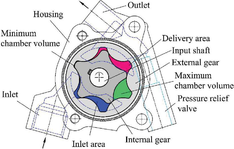
Figure 1 The gerotor pump schematics.
The impeller of the gerotor pump is a trochoidal gear pair, of which the internal gear is mounted on the input shaft. The pump body has fluid outlets which are connected to pump suction line and delivery line. The functional characteristics of the pump, in addition to the operating condition, are significantly influenced by the gear pair set geometric parameters.
There are several methods for the geometric profiles design of the gerotor gear pair set [1, 2]. One group of researchers proposed generating a profile by equidistant modification of the epitrochoid and its conjugated envelope [3–5]. The second one, used cycloidal gear tooth design method [6] and third one is by using the circular pin gear generating technique [7]. Also, there are numerous approaches to improve the pump performance and efficiency. Significant contributions to the investigation of the benefits of the of plastics components application in trochoidal machines have been made in the [6, 8–10]. The higher area efficiency, the outlet pressure and the outlet flow, with a larger span angle of the gerotor pump tooth profile, is shown in [11]. The impact of real-life technological clearances on the pump performance is studied by numerical simulation in [12, 13]. The proportional wear rate factor (WRPF) proposed in [14] is used as an indicator of the wear rate in dry contact conditions [13, 15].
Taking into account previous research in the field of gerotor pumps, this paper presents some of the possibilities for improving pump performance, primarily the reduction of undesirable wear of gear teeth meshing.
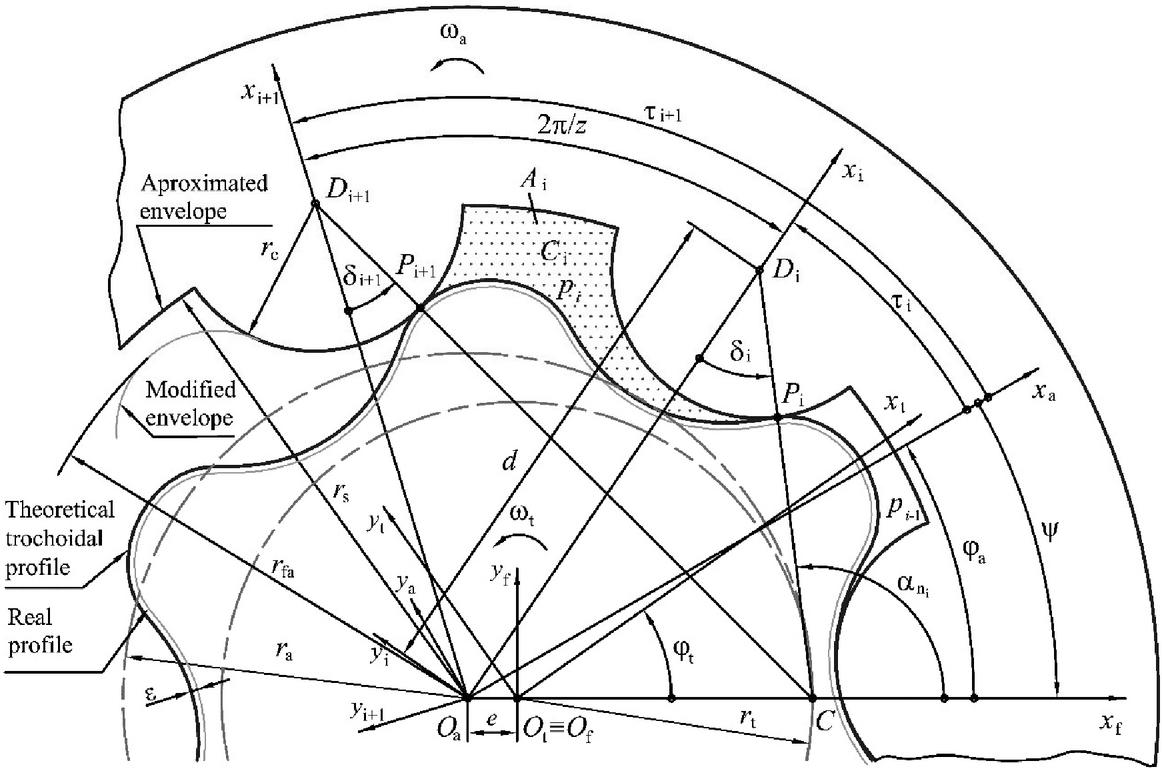
Figure 2 Gerotor pump gears meshing model.
Gerotor Pump Gears Meshing Model
Gear profile design approach proposed in [3–5] is adopted. The internal gear profile is equidistance of the epitrochoid generated by rolling the inside of a larger circle r on a smaller fixed circle r. The external gear profile is the equidistance of the conjugate external envelope, described by circular arc with r radius (see Figure 2). Figure 2 presents a meshing model of the gerotor pump gears. Theoretical trochoidal meshing profiles have as many contact points, as the number of teeth z of the external gear. When modeling teeth, as well as for simulating meshing, it is necessary to generalize the equations of the profile points coordinates applicable to all teeth. The internal gear profile (Figure 2) is defined by coordinates of the contact point P in the coordinate system of the trochoid using the following equation:
| (1) |
where the subscript denotes that considered point belongs to a profile, while the superscript indicates the referent coordinate system.
In Equation (1), is the trochoid coefficient which defines the relation between the trochoid radius and moving circle radius, , c is the equidistant coefficient, which defines the relation between the equidistant radius and eccentricity, , and is the leaning angle:
| (2) |
In the coordinate system , Equations (1) are transformed into form that defines the contact line of meshing profiles:
| (3) |
And in the coordinate system of the envelope , they define the external gear profile:
| (4) |
The following relations apply to the considered model of the gerotor pump in which the shaft is connected to the internal gear: and .
Procedure for Improving Gerotor Pump Performance
Problem Description
Basic requirements set for the gerotor pumps are to provide needed capacity, pressure and reliability, with minimal pump mass, minimal flow pulsation and less wear. The design of the gerotor pump is realized according to the required capacity, so this is a key condition that must be met. In order for the designed pump to correspond to the space where it is intended for, it was adopted that the following parameters be independent: the gear width b, eccentricity e, and radius of the root circle of the external gear r (see Figure 2). The values of the external gear teeth number z, coefficients and c, are varied in order to obtain their best combination in accordance with the defined requirements.
Geometric and Kinematic Conditions
In this section the conditions that should be fulfilled by pair of meshing profiles in order to be potentially applied in practice are defined. The conducted analysis was focused on preventing several types of interference in order to ensure the proper functioning and installation of gear pair. In order to obtain a profile with improved characteristics, conditions are defined that prevent extremely high values of specific sliding and ensure uniform wear of the flanks of the teeth of meshing gears, from the aspect of kinematics. These geometric and kinematic conditions for trochoidal gearing design are given in the Table 1.
Table 1 The geometric and kinematic conditions for trochoidal gearing design
| No. | The Limit to Prevent/Achieve | Condition/Formula |
| 1. | The trochoid does not have peaks | |
| 2. | The higher chamber volume | |
| 3. | The correct gear assembly | |
| 4. | The contact line loop appearance | |
| 5. | The gear profile undercutting | |
| 6. | The interference of the neighboring external gear | |
| teeth profiles | ||
| 7. | The interference of the meshing gear teeth profiles | |
| 8. | The uniform teeth wear at the point with the | |
| highest sliding velocity |
In the Table 1 parameter S is root circle of the external gear coefficient, .
The main criterion is fast generation of the optimal combination of geometric parameters, from the aspect of minimizing the maximum equivalent curvature of the meshing gear tooth profiles, defined by the following equation:
| (5) |
Improving Commercial Pumps
Three representative models were selected in this section. One of them is commercial, Model 1, and the other two, Model 2 and Model 3, were obtained as a result of applying the methodology developed for optimal design [16], in order to improve the existing gerotor gear set design of lubrication pump, capacity of cc/rev and working pressure of MPa. Table 2 shows design parameters of the gear sets geometry.
Table 2 Design parameters of the gear sets geometry
| Gear set | c | S | e (mm) | b (mm) | ||
| Model 1 | 6 | 1.575 | 3.95 | 7.5 | 3.56 | 16.46 |
| Model 2 | 6 | 1.375 | 2.75 | |||
| Model 3 | 5 | 1.850 | 3.75 |
For all three gear sets the material properties are: Young’s modulus, MPa and Poisson’s ratio, . Other parameters are input angular velocity, s and technological clearance, mm.
Pump Performance Indicators
According to the previous sections, the parameters that determine the gear teeth profile, and thus the performance of the gerotor pump, have been identified. Three indicators are used to evaluate the pump performance, and to perform the improving procedure: the flow rate irregularity , the wear rate proportional factor (WRPF) and the chamber pressure variation .
Volumetric Characteristics
In order to obtain a functional dependence that would provide the design of a pair of pump gears, based on the required pump capacity, a mathematical model of the volumetric characteristics of the gerotor pump was developed. First, the instantaneous pump chamber volume was considered [17] and then, the following formula to determine the theoretical volume variation in the active chamber is obtained:
| (6) |
Further, the formula for determined the theoretical flow of a gerotor pump is defined:
| (7) |
Finally, the equation for calculating the pump capacity is obtained:
| (8) |
where m and n are the ordinal numbers of starting and the final chambers which can be found at the same time in the thrust phase.
Flow Rate Irregularity
As an indicator of flow non-uniformity, the flow rate irregularity is used, which is calculated by the formula:
| (9) |
where Q is the maximum flow rate, Q is the minimum flow rate and Q is the average flow rate [15].
Figure 3 shows diagrams of the gerotor pump volume characteristics with gear set Model 2 and Model 3 as a function of external gear rotation angle, based on which their size and variation can be observed.
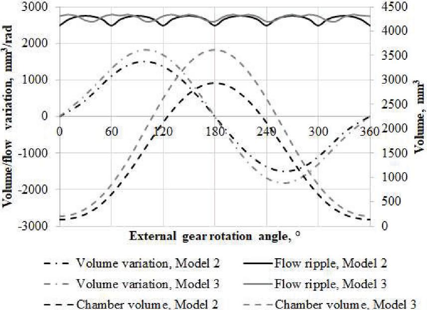
Figure 3 Volumetric characteristics for Model 2 and Model 3.
The differences of pump flow variation for both considered six-chamber gear sets, are negligible [18]. This is confirmed by the calculated values of the flow rate irregularity, which for both six-chamber models amount to %. For a five-chambers pump model, the value was obtained, which confirmed that pumps with an even number of chambers have higher pulsations, and therefore it is recommended to choose an odd number of working chambers in pumps designing.
Wear Rate Proportional Factor
The wear of the Gerotor pump rotor is affected by the sliding velocity and Hertzian contact stress. Therefore, it is convenient to use the Wear Rate Proportional Factor (WRPF) to study both the sliding velocity and Hertzian contact stress. WRPF proposed by [14] is proportional to the wear rate between the rotor of the Gerotor pump in quasi-static and dry contact conditions [13], and is defined as follows:
| (10) |
where is the contact stress, v is sliding velocity at the contact point:
| (11) |
and is angular velocity of the internal gear.
For contact stress calculation, when the gears are made of the same material, and , the following expression is evaluated through the classic Hertz theory [19]:
| (12) |
In Equation (12) F is normal force of the gear pair at the i-th contact point which is formulated as:
| (13) |
where p and q are the ordinal numbers of the initial and the final tooth of the external gear that transfer the load, is the angle between the axis x and the normal CP, and is the total moment of normal forces with respect to the gear center that is equal to the sum of drive moment and pressure force moment with respect to the center of the internal gear [17].
In Equation (12) is equivalent radius of curvature of meshing profiles at the the i-th contact point which is calculated by the following formula:
| (14) |
where r is radius of curvature of the external gear tooth profile and is radius of curvature at the current point of the internal gear tooth profile, which is determined by the following equation:
| (15) |
In order to create conditions that reduce contact forces, and thus reduce wear, the forces and moments that affect the gerotor pump gear pair are analyzed. Based on the analysis and the developed methodology, a program was made in the software package Mathematica for the identification of teeth in contact and calculation of sliding velocity, contact forces, contact stresses and WRPF in the trochoidal pump gear set. Figure 4 shows values of the contact force and the contact stresses, and Figure 5 shows WRPF, of the different angular positions during one working process phase, obtained by the analytical calculation for three considered gerotor set models.
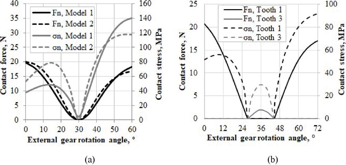
Figure 4 The contact forces and contact stresses for: (a) Model 1 and Model 2, tooth 1 (b) Model 3, tooth 1 and tooth 3.
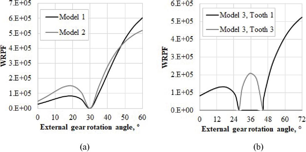
Figure 5 Wear rate proportional factor (WRPF) for: (a) Model 1 and Model 2, tooth 1, (b) Model 3, tooth 1 and tooth 3.
The diagrams show that the newly generated Model 3 gives the lowest value of the maximum contact stress compared to the value obtained in the commercial pump Model 1, up to 35%, while the lowest value of the WRPF factor obtained in Model 2, approximately 14% compared to Model 1.
Pressure Variation in the Pump Chambers
Pressure variation due to the fluid flow
In a gerotor pump the fluid distribution is done through the holes with variable fluid flow area, because it is assumed that fluid flow area is equal to instantaneous chamber area. This assumption led to expression for calculation of the pressure variation during the fluid flow in the active chamber in the following form [17]:
| (16) |
where is the fluid density and A is the instantaneous chamber area.
Based on calculated pressure variation , in the pump chambers, the following equations for chamber pressure calculation could be written: for the inlet chambers, , and for the outlet chambers, [17].
Pressure variation due to clearance
The previously described research considered a theoretical trochoidal profile with assumptions about ideally accurate geometry. However, in real pump designs, the tooth profiles are made with technological clearances, which are necessary to allow proper assembling and meshing of the gears. In order to model of the meshing of profiles with clearance it is adopted that a real profile of the internal gear was obtained by a modification of the trochoid with constant difference increased by the clearance size, (see Figure 1), [20, 21].
The inevitable gaps between the tooth profiles lead to the occurrence of fluid leaks between adjacent chambers. Only losses due the fluid pressure and losses due to the working fluid viscosity (as a consequence of adhesion forces, fluid particles are paste to the side of gear tooth) are considered [21]. When considering the flow variation in pump chamber C, it is assumed that the flow Q that comes from the adjacent chamber is positive (inflows into the chamber C), while the flow Q is negative, since it is pushed from the chamber C to the adjacent chamber. The flowing of the fluid through the gap between the profiles of the teeth is caused by the difference of pressures between the two adjacent pump chambers. To calculate these losses, a hydraulic fluid flow model through rectangular notch with variable dimensions is adopted. Basic geometrical relations for determining the height of the gap between gear profiles are presented in [18]. For calculating the gap height, the internal gear profile is approximated by a circular arc of the radius which is equal to the radius of curvature of trochoid profile at the point P, with technological tolerances [2]. On the basis of this, an equation can be written for calculating the height of the gap in following form:
| (17) |
In Equitation (17) the sign “” refers to the convex, and the sign “” is refers to the concave zone of the profile, h is the minimum clearance between gear profiles [18].
In a limited segment defined by around h, the cross-section of the gap between profiles of gears through which fluid flow can be modeled with rectangles of constant dimensions. For the limit value of a, the value of coordinate x are used for which related gap height according to Equation (17), which is not much larger than h, means . In order to make a deviation from the accurate calculation of cross-section surface negligible, limits of the relative error are set in advance, in particular:
| (18) |
where P is the value of the real surface of the cross-section of the gap and P is the approximate value of surface obtained by approximating the geometrical form of the gap.
Upon the analysis presented in [21], the final form of equation for the calculation of flow rate through the gaps between related profiles of gears for the considered active chamber C can be obtained:
| (19) |
where is fluid dynamic viscosity.
Volumetric losses significantly affect the pressure variation in pump chambers. According from Equation (15) and taking into account the flow losses defined by (19), an expression for calculating the pressure change in the chamber depending on the gap height between the tooth profiles is obtained:
| (20) |
The analysis of the influence of the trochoid coefficient and the gap height on the pressure change in the pump chambers as a function of the external gear rotation angle for the ideal and real tooth profile is graphically shown in Figure 6, for Models 1 and 2, and in Figure 7, for Model 3.
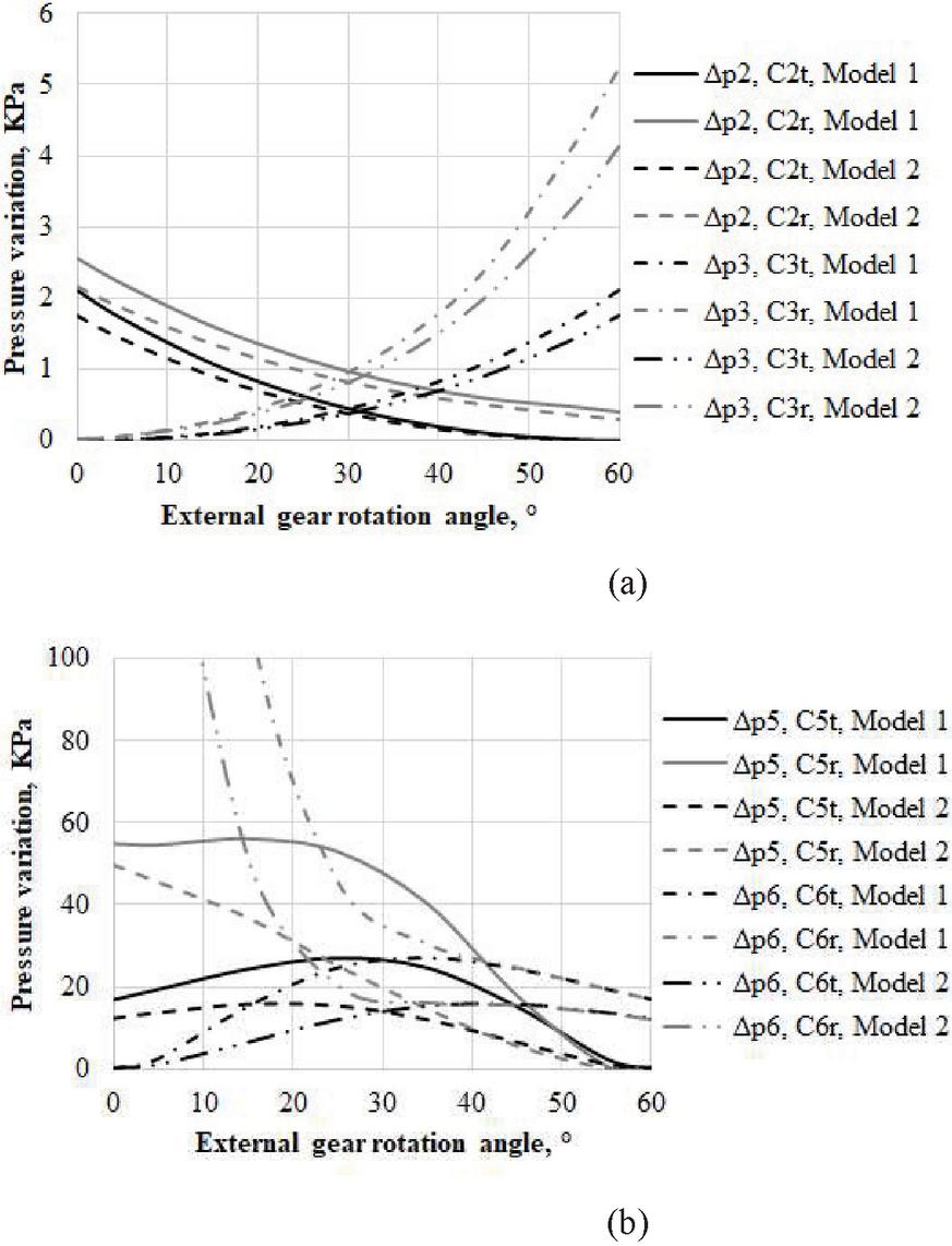
Figure 6 Chamber fluid pressure diagram variation for Model 1 and Model 2: (a) in the chambers 2 and 3, (b) in the chambers 5 and 6.
In the legend in Figures 6 and 7, the index t refers to the theoretical profile, and r to the profile with the technological clearance.
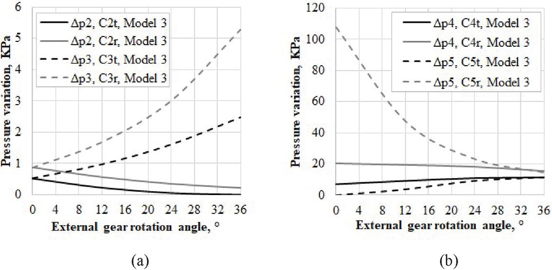
Figure 7 Diagram of the chamber fluid pressure variation for Model 3: (a) in the chambers 2 and 3, (b) in the chambers 4 and 5.
Comparative diagrams are given only for the transition zone between the suction and thrust phases due to significant pressure differences. Based on the presented diagrams, it can be concluded that with the presence of the gap, the size of the changes is larger, but the trend is maintained that with the increase of the coefficient , the size of these changes increases, for six-chamber models. By comparing the shown diagrams for six-chamber and five-chamber pump, it can be noticed that the trend of pressure change in the chambers is similar, but the maximum values are lower in five-chamber Model 3.
Based on the presented results, it can be concluded that the influence of the gap on the pressure change is greatest at the end of the thrust zone and entry into the suction zone, which can be explained by the largest pressure difference between adjacent chambers. The highest pressure values change are achieved at the beginning of the considered phase period, in chamber 6, in the Model 1.
Experimental Validation
The experimental testing of gerotor pump with three considered gear sets was done in laboratory with real operating conditions simulation (see Figure 8). The layout of the test rig was in accordance with the hydraulic circuit shown in Figure 9. The tested gerotor pump was driven by electric motor up to 2.2 kW. The working medium of the pump was SAE 15W30 mineral oil, and the oil temperature was maintained within C. The speed is adjusted by a speed controller and measured by a contactless tachometer. In doing so, three values of the pump rotational speed were varied (500 rpm, 1000 rpm and 2000 rpm).

Figure 8 Gerotor pump test rig.
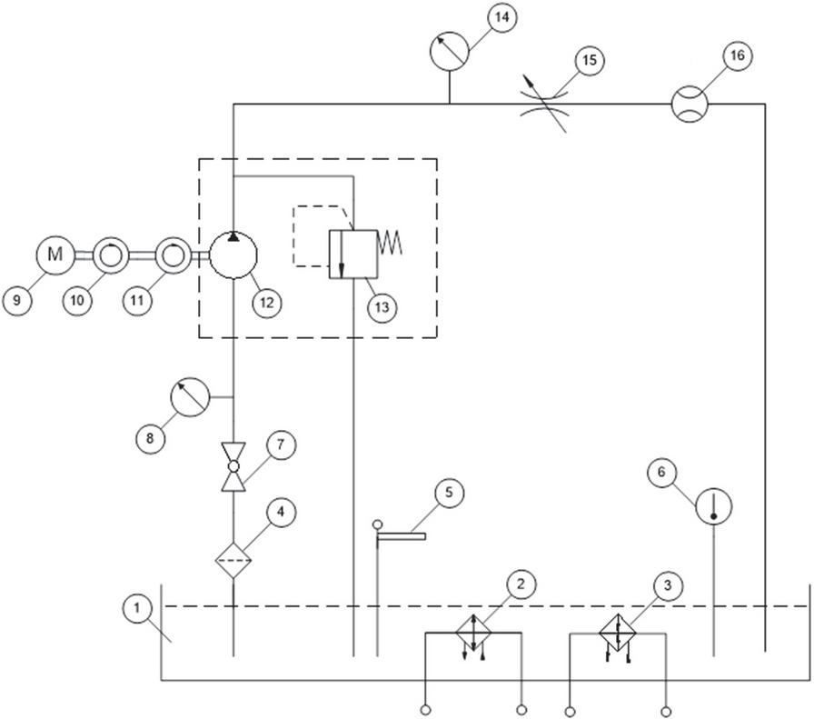
Figure 9 ISO schematic of test rig: 1-tank, 2-cooler, 3-heater, 4-filter, 5-oil level indicator, 6-temperature gauges, 7-ball valve, 8-vacuum gauge, 9-motor, 10-tachometer, 11-torque meter, 12-tested pump, 13-safety valve, 14-pressure gauge, 15-valve, 16-flow meter.
A vacuum gauge was used to measure the intake pressure of the pump working fluid, while a pressure gauge was used to measure the discharge pressure of the working fluid. The test rig enabled measurements of the outlet flow rate by a flow meter. Measuring the pump flow rate was performed at the discharge pressure of the pump from 0 up to 1 MPa in increase steps of 0.1 MPa.
The measurement results of the pump flow rate and volumetric efficiency, as a function of discharge pressure, are shown in the Figures 10 and 11, respectively. Based on the shown diagram, it can be observed that there is a linear relationship between the flow rate and the discharge pressure, and the output flow was approximately 13 l/min at 1000 rpm, which is about 7% less than the calculated value pump capacity (14 cc/rev). In addition, it was observed that the value of the volumetric efficiency is higher for the Model 2 and at higher rotational speed.
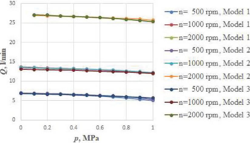
Figure 10 Flow rate diagram.
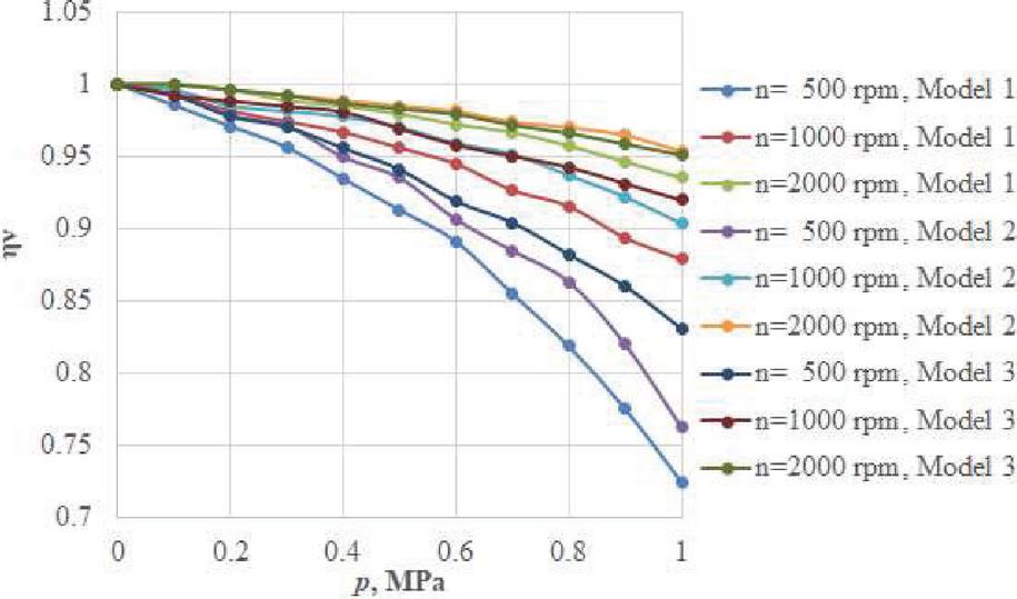
Figure 11 Volumetric efficiency diagram.
The deviation between the calculated and experimentally measured flow was found during the experiment, but as the pumps tested on the same device from the regular manufacturing process showed the same difference, the newly made model was considered to satisfy the experimental validation and as such could be to use in practice.
Conclusions
Gerotor are low pressure pumps in which one of the negative occurrence is wear and consequent increase of the gap between the coupled tooth profiles, which can lead to fluid losses, then additional dynamic forces, reduce stability and increase noise and vibration. In order to reduce these negative effects, relevant geometric parameters were identified, as well as indicators for assessing the effects of changes in geometric parameters on pump performance. For this purpose, geometric-kinematic constraints have been formulated and a mathematical model for defining the volumetric characteristics of the gerotor pump has been developed. Also, the procedure for calculating volume losses and pressure changes in the pump chambers due to the gap between the meshing tooth profiles is defined. A factor WRPF was adopted as a parameter of profile wear sensitivity.
By applying a defined mathematical model, through the variation of influential parameters and simulation of operating conditions, three gear sets of were selected, one of which is commercial, and the other two proposed improved solutions. The obtained results showed that with six – chamber pumps of the same width and foot diameters of the external gear, there are no significant changes in volume characteristics, while with five – chamber pumps, a smaller flow irregularity was confirmed. It was shown that the highest values of pressure change were achieved at the end of the thrust zone and the suction zone entry in chamber 6, in the commercial model. Also, the newly created five – chamber model gives the lowest maximum contact stresses compared to commercial pumps, up to 35%, while the highest WRPF factor was obtained in the newly created six – chamber model, approximately 14% compared to the commercial ones. The experimental results, along with all other presented results, were confirmed that more beneficial indicators are derived from the six – chamber model proposed as a solution with improved characteristics compared to the existing commercial ones. Future work will be focused on including the influence of the coefficient of friction and material type of gerotor gear set on the pump performance.
Acknowledgment
Research presented in this paper was supported by Ministry of Education, Science and Technological Development of Republic of Serbia, Grants TR 35033 and TR 33015.
References
[1] Nang, A., Maiti, R.: Unification of epitrochoid origin profile design approaches for external lobed star member used in hydrostatic and gear units. Journal Mechanical Science 227(2), 299–310 (2012).
[2] Gamez-Montero, P. J., Castilla, R., Codina, E.: A Review of Gerotor Technology in Hydraulic Machines. Energies 12, 2423 (2019).
[3] Maiti, R., Sinha, G. L.: Kinematics of active contact in modified epitrochoid generated rotary piston machines. Mech Mach Theory 23, 39–45 (1988).
[4] Gamez-Montero, P. J., Castilla, R., Codina, E.: Methodology based on best practice rules to design a new-born trochoidal gear pump. Proceedings of the Institution of Mechanical Engineers, Part C: Journal of Mechanical Engineering Science 232(6), 1057–1068 (2018).
[5] Ivanovic, L. Josifovic, D.: Specific Sliding of Trochoidal Gearing Profile in the Gerotor Pumps. FME Transactions (34), 121–127 (2006).
[6] Stryczek, J., Bednarczyk, S., Biernacki, K.: Gerotor pump with POM gears: Design, production technology, research. Archives of Civil and Mechanical Engineering, 14(3), 391–397 (2014).
[7] Beard, J. E., Yannitell, W., Pennock, G. R.: The effects of the generating pin size and placement on the curvature and displacement of Epitrochoidal Gerotors. Mech Mach Theory 27, 373–389 (1992).
[8] Stryczek, J., Banaś, M., Krawczyk, J., Marciniak, L., Stryczek, P.: The fluid power elements and systems made of plastics. Procedia Engineering, Elsevier 176, 600-609 (2017).
[9] Gamez-Montero, P. J., Antoniak, P., Castilla, R., Freire, J., Krawczyk, J., Stryczek, J., Codina, E.: Magnet-Sleeve-Sealed Mini Trochoidal-Gear Pump Prototype with Polymer Composite Gear. Energies (10), 1458 (2017).
[10] Gamez-Montero, P. J., Garcia-Vilchez, M., Raush, G., Freire, J., Codina, E.: Teeth clearance and relief grooves effects in a trochoidal-gear pump using new modules of GeroLAB. Journal of Mechanical Design, Transactions of the ASME 134(5), (2012).
[11] Hsieh, C.F.: Flow Characteristics of Gerotor Pumps with Novel Variable Clearance Designs. Journal of fluids engineering-Transactions of the ASME 137(4), 041107 (2015).
[12] Pellegri, M., Vacca, A.: Numerical simulation of Gerotor pumps considering rotor micro-motions. Meccanica 52(8), 1851–1870 (2017).
[13] De Martin, A., Jacazio, G., Sorli, M.: Optimization of Gerotor Pumps with Asymmetric Profiles through an Evolutionary Strategy Algorithm, Machines 7(1), 17 (2019).
[14] Kwon, S. M., Kim, M. S., Shin, J. H.: Analytical wear model of a gerotor pump without hydrodynamic effect. J Adv Mech Des Syst 2, 230–237 (2008).
[15] Karamooz Ravari, M. R., Forouzan, M.R., Moosavi, H.: Flow irregularity and wear optimization in epitrochoidal gerotor pumps. Meccanica 47, 917–928 (2012) doi: 10.1007/s11012-011-9473-6
[16] Ivanovic, L.: Reduction of the maximum contact stresses by changing geometric parameters of the trochoidal gearing teeth profile. Meccanica 51(9), 2243–2257 (2016).
[17] Ivanović, L., Devedžić G., Mirić N., Ćukovic S.: Analysis of forces and moments in the gerotor pumps. Proceedings of the Institution of Mechanical Engineers. Part C: Journal of Mechanical Engineering Science 1(1), 1–13 (2010).
[18] Ivanović, L. (2021) Design, Modeling and Simulation of Gearing for Improving Gerotor Pump Performance. In: Stryczek J., Warzyńska U. (eds) Advances in Hydraulic and Pneumatic Drives and Control 2020. NSHP 2020. Lecture Notes in Mechanical Engineering. Springer, Cham. https://doi.org/10.1007/978-3-030-59509-8\_2
[19] Maiti, R.: Active contact stresses at epitrochoid generated rotor-stator set of fixed axis or equivalent system ROPIMA type hydrostatic units. Journal of Engineering for Industry 113, 465–473 (1991).
[20] Ivanovic, L., Devedzic, G., Cukovic,S., Miric, N.: Modeling of the Meshing of Trochoidal Profiles with Clearances. Journal of Mechanical Design 134(4), 041003-1/041003-9 (2012).
[21] Rundo, M.: Models for Flow Rate Simulation in Gear Pumps: A Review. Energies 10, 1261 (2017).
Biographies

Lozica Ivanović is a professor at the University of Kragujevac, Faculty of Engineering, Serbia. She received her Ph.D. in mechanical engineering from University of Kragujevac in 2007. Her research interests includes: mechanical design, generating special tooth profile applied in mechanical construction, especially trochoidal profile, analysis and design of gerotor pump, industrial design. She is Editor of journal Applied Engineering Letters.

Miloš Matejić is an assistant professor at the University of Kragujevac, Faculty of Engineering , Serbia. He received his Ph.D. in mechanical engineering from University of Kragujevac in 2019. His research interests includes: machine elements, power transmission, CAD and expert systems in machine design. He is reviewer in one journal publishing by Springer, and one journal publishing by Elsevir.
International Journal of Fluid Power, Vol. 21_3, 327–346.
doi: 10.13052/ijfp1439-9776.2132
© 2020 River Publishers