Internal Leakages in a Water Hydraulic Pump with Gears From Plastic
Michał Banaś
Wrocław University of Science and Technology, Wroclaw, Poland
E-mail: michal.banas@pwr.edu.pl
Received 05 December 2020; Accepted 06 December 2020; Publication 06 February 2021
Abstract
Plastics are used more and more in hydraulic systems. The chemical properties of the plastics favour the use of working fluids alternative to mineral oil, e.g. water. The conditions in the manufacturing process, e.g. injection moulding, limit the achievement of high working pressures in the hydraulic elements. Internal leakage reduces the efficiency of the hydraulic pump with plastic gears. The article presents the results of internal leakage tests of a water-supplied hydraulic pump. Gears made of various materials (PPS+GF40 and PEEK) have been used in the research, made by two methods: injection moulding and machining. A simplified mathematical model of the dependence of leakages on pressure and rotational speed has been developed. The influence of the materials and manufacturing methods used on the pump operation is discussed.
Keywords: Composites, PEEK, PPS+GF40, clearances, tap water, internal flow.
1 Introduction
Plastics have been used in hydraulic systems for many years. They can be found in auxiliary parts, e.g. housings or seals. However, not too many plastics are used for elements subjected to medium or high working pressure (e.g. 16 MPa). Many features of polymer materials, incl. flexibility, chemical resistance, great freedom of forming the shape while maintaining low production costs [1] make more and more solutions for hydraulic components with these materials.
Most hydraulic systems use different types of hydraulic oil. In some machines, restrictions due to flammability of liquids, environmental protection and other criteria do not allow their use. In such situations, mineral oils are replaced by other working fluids, e.g. mixtures of oil and water, non-flammable water-based fluids or water only. The mentioned liquids, apart from numerous advantages, such as approval for use in demanding conditions, fire resistance, can be chemically aggressive towards the materials used with oils. An example may be water. The high reactivity of water requires the use of stainless steels or appropriate coatings [2]. Both solutions increase the costs of manufactured hydraulic components. The answer to these challenges are plastics, which can also maintain the required strength, while maintaining high chemical resistance.
Injection moulding, one of the basic methods of producing plastic parts, is associated with component quality limits, such as dimensional accuracy or surface condition, relative to machining. With water-driven hydraulic systems, clearances and surface quality are particularly important due to fluid parameters. The viscosity is lower than that of oil and results in higher dimensional requirements.
2 Plastics in Hydraulic Systems
The share of plastics in selected areas of hydraulics is growing. There are many works on the use of the positive features of polymers in hydraulic systems, e.g. lowering the friction coefficient in bearings [3], reducing the production costs of complex elements such as gerotor gears, [4], creating new solutions valve bodies [5], the use of plastic properties in research on design solutions of gears in pumps [6] and gears [7].
In addition to research work, companies are also trying to introduce plastics to the hydraulic system market. An example is the use of a composite hydraulic cylinder cover [8].
The widespread use of plastics is limited primarily by three criteria:
• strength
• stiffness
• dimensional stability
The strength of plastics varies. The entire family of plastics includes a group of engineering plastics. After appropriate modifications, they can be significantly loaded while maintaining the required rigidity. For hydraulic systems, these two parameters – strength and stiffness – are important because they affect the range of the working pressure and the volumetric efficiency of the systems.
Another criterion is the accuracy of the components, especially manufactured by using injection moulding. Maintaining the repeatability of the dimensions tolerated in the elements significantly increases the production costs, which makes it difficult to introduce plastics into the hydraulic systems, especially at operating pressures above .
Next aspect of using plastics are the differences in the mechanical and physical parameters of plastics that are greater than for the currently used materials. This is due to the use of many additives and the influence of the production process parameters on the quality of semi-prepared products. These differences are observed even for materials with similar or the same chemical composition.
Average values are often given in the literature. A detailed analysis of the available data shows that the ranges of the selected parameters may be wide. Table 1 presents the list of mechanical parameters for selected materials, taking into account many extreme cases. The difference between the limit values may result from special cases of the material provided by the manufacturer, e.g. the chemical composition covered by a patent, or the adopted test method, which is not always provided. This dispersion of values presents a major challenge in the design and construction of hydraulic components.
Table 1 Ranges of mechanical parameters of selected materials according to different manufacturers, taking into account different conditions for the preparation of an element from a given material or its operation, e.g. working temperature, drying of granules, etc. [9, 10]
| Parameter (Unit) | PPS | PEEK | PPS+CF30 | PPS+GF40 |
| Density () | (1.34–2.26) | (1.26–1.50) | (1.40–1.69) | (1.35–1.80) |
| Modulus of tensile | ||||
| elasticity (GPa) | (3.40–17.2) | (2.2–6.48) | (7.0–32) | (3–37) |
| Yield Limit (MPa) | (27.6–150) | (65–120) | (95–173) | (60–180) |
With a wide dispersion of mechanical parameters, the hydraulic parameters of working fluids are another challenge. The use of fluids with a lower viscosity than conventional mineral hydraulic oils requires considerable attention at the design stage as it can lead to a reduction in efficiency (Table 2). The low viscosity of some liquids () facilitates the flow in internal gaps and may lead to leaks many times greater than in typical hydraulic systems [14]. As a consequence, motion resistance increases and it is an important problem in many pumps and motors [15, 16].
Table 2 Selected parameters of oil and water at temperature [11, 12, 13]
| Hydraulic | Water | Hydraulic | Oil-in-water | ||
| Fluid | Oil | Oil | Emulsion | Glycol | |
| Designation | HLP-68 | tap water | HLP-32 | HFB-68 | PAG |
| Viscosity () | 150 | 0.89 | 70 | 160 | 180 |
| Density () | 870 | 997 | 870 | 910 | 980 |
| (1) interpolated; (2) at | |||||
In such a complex design and technological situation, it seems reasonable to determine internal leaks and to develop a simplified mathematical model. The mathematical models of leaks in pumps and hydraulic motors take various forms, from the simplest [17], through complex but taking into account the general parameters of the elements, to detailed lumped-element models of the multi-chamber flow [18, 19].
Changing flow parameters, including decreasing resistance, partially compensate for the increase in leakage. The greater chemical resistance of typical plastics is also an advantage, but may not be sufficient to balance the energy consumption of such systems. Considering the above-mentioned challenges to plastics in hydraulic systems, an attempt was made to investigate internal leakage in a plastic hydraulic pump and to develop a simplified mathematical model.
3 Research Object
Figure 1 shows a hydraulic pump with cycloidal gears made of plastic. The internal gear 3 cooperates with the external one 2. The gear 2 is seated on the drive shaft 4 using three keys 5 to distribute stress evenly. The gears 2 and 3 rotate and pump the liquid from the input area (IN) to the output area (OUT) of the front cover 1. The steel shaft 4 is supported in the bearings located in the front 1 and rear part of the aluminium body.
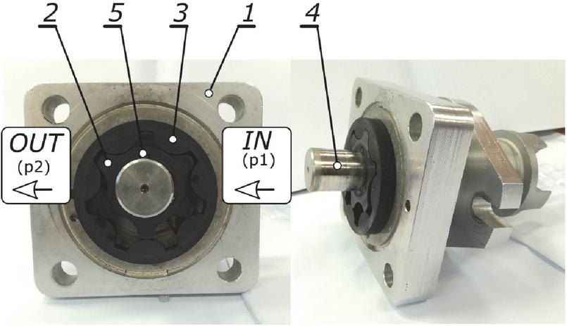
Figure 1 Tested gear pump. (a) view of the pump with an exemplary set of gears mounted, (b) view of the front part of the body; 1 – front cover, 2 – external toothed gear, 3 – internal toothed gear, 4 – input shaft, 5 – keys.
The four sets of gears Figure 2 used in the tests were made using three methods from two different materials. All sets consist of a 6 tooth external gear and a 7 tooth internal gear. Gears (a) and (b) are made of a PPS-based composite with 40% glass fiber (PPS+GF40). Pure poly-(ether)ether ketone (PEEK) is used in gears (c) and (d). In (a), (b) and (c) sets, the injection moulding method was combined with machining. After checking the surfaces obtained with the method of injection, additional machining of the subsidence of the end face was made, reducing the unevenness of these surfaces at the growing axial clearance. In gear (a), rough machining was used, while in gears from sets (b) and (c), the machining was finishing due to the better surface condition. For gears (a) marked (PPS+GF40-Ia), the axial clearance was obtained after machining, and for gears (b) marked (PPS+GF40-Ib) the axial clearance .
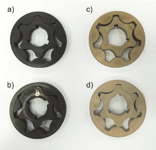
Figure 2 Tested gear sets; injected: (a) PPS+GF40 (variant Ia), (b) PPS+GF40 (variant Ib), (c) PEEK, machined: (d) PEEK.
4 Test Stand and Test Procedure
The tests of the gear pump with all sets of gears were carried out on the stand (Figure 3). An electric motor 2 drove the tested pump 1, which forced water through a throttle valve 3 into a tank 5. The valve 4 protected the pump against pressure increase . The flow rate was measured with a flow sensor 7, and the pressure on the discharge side was measured with a pressure transducer 6. The constant value of the rotational speed of was controlled by the system supplying the station. The inlet pressure was not measured due to the low viscosity of the working fluid (Table 2), maintaining the overpressure in the inlet chamber IN of the pump, resulting from the difference in the height of the liquid mirror and the channel axis input and a short section of the inlet piping. In the further considerations, it was assumed that the inlet pressure is . The temperature of the working fluid was measured with a temperature transducer 8 and maintained by an additional cooling system in the range of . The available measuring transducers designed for operation with water were used in the research (Table 3).
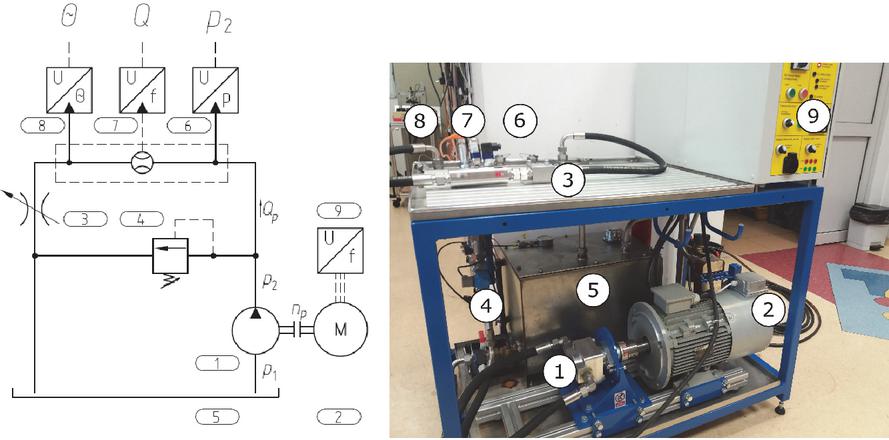
Figure 3 Test stand: (a) diagram of the hydraulic system, (b) view of the stand; 1 – pump, 2 – electric motor, 3 – flow control valve, 4 – pressure relief valve, 5 – tank with additional equipment, 6 – pressure transducer, 7 – flow rate transducer, 8 – temperature transducer, 9 – electric motor control system.
Table 3 Parameters of transducers
| Quantity | Symbol | Accuracy | Full Scale |
| Temperature | K | 125 | |
| Pressure | MPa | 10 MPa | |
| Flow rate | 2% | 60 lpm | |
| Rotational speed | rpm | 6000 rpm |
The research was carried out using the full factorial plan (Table 4). The rotational speed and the pressure were varied and the temperature was kept constant. Three repetitions were made at each measuring point and the mean value was calculated. All curves apply to the discharge pressure . Due to the stability of the pump operation (low volumetric efficiency ), not all the assumed measurement points were tested. Internal leakage was determined by indirect method by subtracting from the theoretical capacity , calculated at , the measured flow rate [20]. In some measuring points, the results presented in [14] were used.
Table 4 Measuring points according to the full factorial plan
| Parameter | Symbol | Measuring Points |
| Pressure (MPa) | 0.05, 0.10, 0.20, 0.40, 0.60, 0.80, 1.0, 1.2 | |
| Rotational speed (rpm) | 1000, 1500, 2000 |
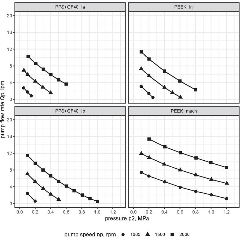
Figure 4 Flow rate of the pump as a function of the outlet pressure for selected speeds () for gears made of different materials.
5 Research Results and Statistical Analysis
Figure 4 shows the pump flow rate as a function of pressure at various rotational speeds for all tested gears. The flow rate of the pump changes according to the general dependencies for hydraulic pumps, i.e. with an increase of the speed the flow rate increases too and with an increase of pressure it decreases. The greatest decrease is observed for injected and additionally machined gears (PS+GF40-Ia, PPS+GF40-Ib, PEEK-inj), e.g. for gears PPS+GF40-Ib flow rate decrease was with a pressure increase of for rotational speed . For machined only PEEK-mach gears, the difference is for a pressure increase of and the same rotational speed. In turn, the difference in with increasing pressure is similar for different speeds, e.g. for gears PEEK-mach with the pressure difference for and for . This indicates a small share of the rotational speed and a significant share of the pressure in the overall impact on the pump flow rate . The same relationship is visible for the remaining gear sets. With machined gears PEEK-mach, the rotational speed is more important for the delivery of the pump than for the other gears, with efficiency for and for .
There is a significant difference in the flow rate between the sets of injected and additionally machined gears and the sets of only machined ones. The highest flow is achieved by a pump with gears with PEEK-mach (with i ), and the smallest for similar parameters pump with gears PS+GF40-Ia.
Similar dependencies are also visible on the characteristics of the pump’s volumetric efficiency (Figure 5). The highest volumetric efficiency in the tested range is maintained by the pump with machined gears PEEK-mach (, with and pressure ). The remaining gears, with the same parameters, provide lower efficiency ( have gears PPS+GF40-Ia, and have gears PEEK-inj).
The rotational speed is important for injected and machined gears. For gears PPS+GF40-Ib the efficiency increases from for at the pressure of to at . The smaller change is for PEEK-inj gears. Efficiency varies from to with similar parameters. An even smaller difference occurs with machined gears PEEK-mach ( for to at and pressure ).
It is caused by smaller axial clearances and radial matching of the tooth profiles. The described influence of the pressure and the rotational speed on the flow rate and the volumetric efficiency of the pump indicate a higher quality of machined gears and the lack of improvement in the pump operation, resulting from a better surface quality. The material of the gears has no influence on this relationship. Injection-moulded and machined gears in both materials (PPS and PEEK-mach) behave similarly.
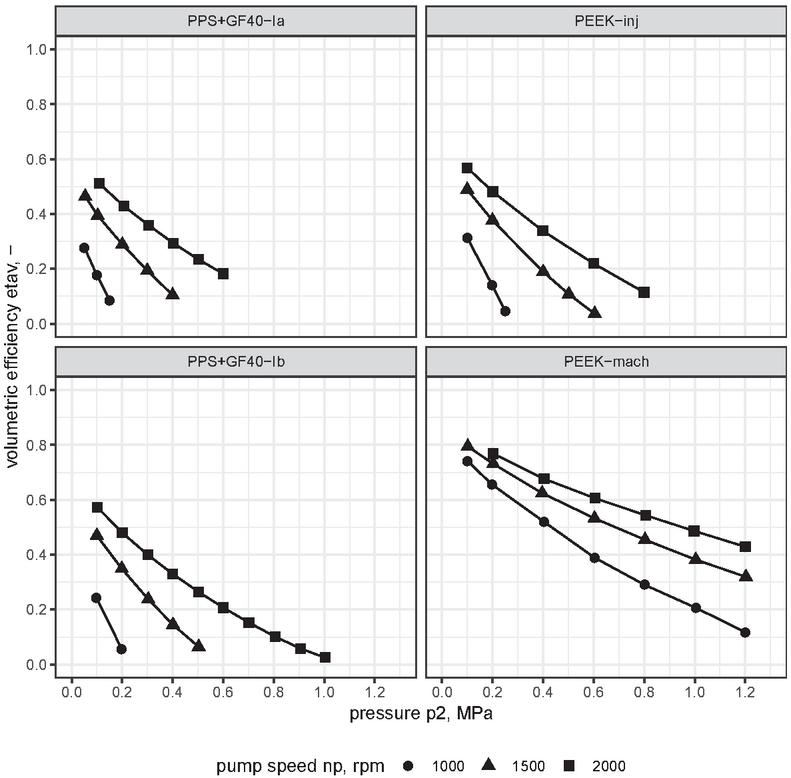
Figure 5 Pump volumetric efficiency as a function of outlet pressure for selected rotational speeds () for gears made of different materials.
Internal leakage in the pump was determined by an indirect method, as of the difference between the theoretical capacity and the measured flow rate
Figure 6 shows the obtained calculation results for the measurement data. Injection moulded and machined gears have greater leakage (e.g. gears PPS+GF40-Ia , with and ) than only machined gears (, with and ). For both gear variants PPS+GF40-Ia () and PPS+GF40-Ib () there is no big difference in leakage flow rate for the sample parameters ( and ). The same goes for the lower pressure. With and the flow rate is (PPS+GF40-Ia) and (PPS+GF40-Ib) respectively.
For PPS gears, the estimate of the leakage value with changing velocity is similar, with and the difference is . For gears with PEEK-inj, additionally machined, the leakage value depends more strongly on the rotational speed, and the most depends on PEEK-mach gears.
Based on the graphs, we find that the influence of rotational speed is small. The leakage depends only on the output pressure . This is due to the large axial clearances and the radial fit of the profiles, which cannot be compensated by material properties, e.g. flexibility.
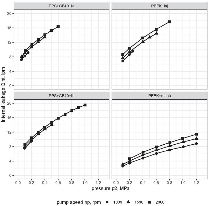
Figure 6 Flow rate of the pump internal leakage as a function of the outlet pressure for selected speeds () for gears made of different materials.
In order to quantify the obtained results and to predict the leakage value , a simplified mathematical model of leakage in the pump was developed. The linear dependence of the leakage flow rate on the pressure (laminar flow), the square root of the pressure (turbulent flow) and the rotational speed of the pump shaft was assumed [17]. The model ignores the influence of temperature due to the low value of water viscosity (Table 2) and the constant value maintained during the tests (Table 4). The model takes into account the constant flow rate depending on other parameters, e.g. gear geometry, design, clearances, marked in the formula as (design and technological parameters):
Using the linear regression method, the values of the coefficients , , , were estimated for each gear set (Table 5). The results confirm the statistical significance () of all determined coefficients. The value for all wheel sets is high (). In PPS+GF40-Ia, PPS+GF40-Ib and PEEK-inj gears, the factor is large, which indicates the influence of other factors on leakage, e.g. axial clearance . In PEEK-mach gears, the value of this coefficient is less than zero () and it does not make any physical sense. It may result from the strong dependence of flow rate on pressure (fraction of laminar flow), especially the square root of pressure (fraction of turbulent flow).
Table 5 The results of the estimation of the parameters of the flow rate regression model
| Estimate | Std. Error | t-value | Pr(>) | |
| Call: PPS+GF40-Ia 19 obs. | ||||
| (Intercept) | 3.647e+00 | 9.865e-02 | 36.97 | 3.77e-16 *** |
| p2_bar_mean | 6.052e-01 | 4.435e-02 | 13.64 | 7.33e-10 *** |
| I(p2_bar_mean^(1/2)) | 2.583e+00 | 1.447e-01 | 17.85 | 1.63e-11 *** |
| n_rpm_mean | 1.432e-03 | 3.406e-05 | 42.05 | <2e-16 *** |
| Call: PPS+GF40-Ib 17 obs. | ||||
| (Intercept) | 2.0160139 | 0.2665674 | 7.563 | 4.11e-06 *** |
| p2_bar_mean | 0.2441342 | 0.0638402 | 3.824 | 0.00211 ** |
| I(p2_bar_mean^(1/2)) | 4.1614989 | 0.2628306 1 | 5.833 | 7.07e-10 *** |
| n_rpm_mean | 0.0010322 | 0.0000953 1 | 0.831 | 7.08e-08 *** |
| Call: PEEK-inj 13 obs. | ||||
| (Intercept) | 1.5554783 | 0.4170853 | 3.729 | 0.00470 ** |
| p2_bar_mean | 0.5069359 | 0.1205896 | 4.204 | 0.00229 ** |
| I(p2_bar_mean^(1/2)) | 2.9864899 | 0.4393359 | 6.798 | 7.93e-05 *** |
| n_rpm_mean | 0.0017942 | 0.0001018 1 | 7.624 | 2.76e-08 *** |
| Call: PEEK-mach 20 obs. | ||||
| (Intercept) | 1.5761963 | 0.4757748 | 3.313 | 0.00440 ** |
| p2_bar_mean | 0.2560352 | 0.0952396 | 2.688 | 0.01615 * |
| I(p2_bar_mean^(1/2)) | 1.6967456 | 0.4389866 | 3.865 | 0.00137 ** |
| n_rpm_mean | 0.0018704 | 0.0001324 | 14.132 | 1.86e-10 ** |
6 Summary and Conclusions
The presented studies show that the plastics PPS+GF40 and PEEK can be used in water gear pumps in short-term operation. The used material PPS+GF40 and PEEK does not affect the volumetric efficiency. The pump was stable and repeatable measurement results were obtained. The tests used injection-moulding gears and machined gears. The method of preparing the gears affects the operating parameters of the pump. It is necessary to pay attention to the special requirements for gears due to working with water as working fluid. When selecting, the chemical compatibility of the material with the liquid must be ensured.
The use of water and water-based hydraulic fluids (low viscosity) requires the development of new rules for the selection of clearances in gears assemblies. The use of gears with tooth profiles selected according to dimensional deviations adopted for oil hydraulics results in high internal leakage and low volumetric efficiency of the pump. Improvement in pump performance can be found in active compensation of axial play, modification of toothed profiles, change of required dimensional tolerances, and deviations in shape and position.
Gears produced solely by machining have a higher efficiency than the other sets. Machining of gears produced by injection moulding caused an increase in the axial play and despite the evenness of the surface contributed to a significant reduction of efficiency. Machining as an additional method improves parameters compared to only injected gears but increases costs. Taking into account the additional effort to improve the surface quality, this type of action should be limited to the necessary minimum, and not to increase the axial clearance. Instead of machining, one should strive to improve the principles of cooperation between the gears and the body by changing the injection parameters or other design solutions of the gear sets and the pump body.
The proposed simplified mathematical model of leaks describes numerically the obtained measurement results separately for each set. In all gears cases, the constant component in the equation has a large share (up to 50%) of the leakage value. This shows that the geometric and technological parameters of the tested gear sets are more important than the operating parameters of the pump.
References
[1] Stryczek, J.; Banaś, M.; Krawczyk, J.; Marciniak, L.; Stryczek, P. The Fluid Power Elements and Systems Made of Plastics. Procedia Eng. 176(204), pp. 600–609 (2017). doi:10.1016/j.proeng.2017.02.303
[2] Krawczyk, J. Sobczyk A., Stryczek J., Walczak P.: Tests of New Methods of Manufacturing Elements for Water Hydraulics. In: Materials Research Proceedings vol. 5, pp. 200–205. (2018). doi:10.21741/9781945291814-35
[3] Rodionov, L., Rekadze, P., and Stryczek, J. (2015). A Gear Micropump without Bearings Production. Applied Mechanics and Materials, 775, 352–356. doi:10.4028/www.scientific.net/amm.775.352
[4] Biernacki, K. (2020). New construction of cycloidal gear unit made of plastics. Proceedings of the Institution of Mechanical Engineers, Part C: Journal of Mechanical Engineering Science. doi:10.1177/0954406220939999
[5] Bonanno, A. (2008). Materialli polimerici applicazioni. Oleodynamica Pneumatica, Aprile, 200876, 79.
[6] P. Antoniak, J. Stryczek, Visualization study of the flow processes and phenomena in the external gear pump, Archives of Civil and Mechanical Engineering, Volume 18, Issue 4, 2018, Pages 1103–1115, doi:10.1016/j.acme.2018.03.001
[7] Bednarczyk, S., Jankowski, L. Krawczyk, J. (2019). The Influence of Eccentricity Changes on Power Losses in Cycloidal Gearing. Bimonthly Tribologia, 285 (3), 19–29, doi:10.5604/01.3001.0013.5430
[8] Parker (2007), Lightraulics® Composite Hydraulic Cylinders For working pressures up to 700 bar, Catalogue HY07-1410/UK.
[9] Plastics, http://www.plastics.pl. Last accessed 12 Nov 2020.
[10] MatWeb, http://http://www.matweb.com/. Last accessed 12 Nov 2020.
[11] Hodges, P. (1996). Hydraulic Fluids. Elsevier Science.
[12] Thelmul Hydraulic Fluid HFB LT 68”, Aztec Oils, 2018.
[13] Lide D.R.: CRC Handbook of Chemistry and Physics. 85th edn. CRC Press LLC, Florida, USA (2004).
[14] Banaś M. (2021) Volumetric Efficiency of a Hydraulic Pump with Plastic Gears Working with Tap Water. In: Stryczek J., Warzyńska U. (eds) Advances in Hydraulic and Pneumatic Drives and Control 2020. NSHP 2020. Lecture Notes in Mechanical Engineering. Springer, Cham. doi:10.1007/978-3-030-59509-8_32
[15] Zhou, H., and Song, W. (2011). Optimization of Floating Plate of Water Hydraulic Internal Gear Pump. Proceedings of the 8th JFPS International Symposium on Fluid Power, OKINAWA 2011 Oct. 25–28, (2011)
[16] Śliwiński, P. (2017). The Influence of Water and Mineral Oil On Volumetric Losses in a Hydraulic Motor, Polish Maritime Research, 24(s1), 213–223. doi:10.1515/pomr-2017-0041
[17] Ivantysyn, J. and Ivantysynova, M.: Hydrostatic Pumps and Motors: Principles, Design, Performance, Modelling, Analysis, Control and Testing. Tech Books International (2003).
[18] Casoli, P., Vacca, A., Franzoni, G. (2005). A Numerical Model for the Simulation of External Gear Pumps. Proceedings of the JFPS International Symposium on Fluid Power. 2005. doi:10.5739/isfp.2005.705
[19] Rundo, M. (2017). Models for Flow Rate Simulation in Gear Pumps: A Review. Energies, 10(9), 1261. doi:10.3390/en10091261
[20] Krawczyk, J, Stryczek, J. (2014), Construction and Experimental Research on Plastic Cycloidal Gears Used in Gerotor Pumps. Proceedings of the 8th FPNI Ph.D Symposium on Fluid Power. 8th FPNI Ph.D Symposium on Fluid Power. Lappeenranta, Finland. June 11–13, 2014. V001T01A006. ASME. doi:10.1115/FPNI2014-7827
Biography

Michał Banaś received the master’s degree in mechanical design from Wrocław University of Science and Technology in 2000, and the philosophy of doctorate degree in Machine Design from WUST in 2005, respectively. He is currently working at the Department of Mechanical Engineering, WUST. His research areas include machine design, mechatronics, hydraulic machines, and plastics. He has been serving as a reviewer for many highly-respected journals. OrcidID 0000-0003-3433-1249.
International Journal of Fluid Power, Vol. 21_3, 347–362.
doi: 10.13052/ijfp1439-9776.2133
© 2020 River Publishers