Influence of Boundary Conditions on the Accuracy of Pulsation Dampers Characteristics in Analytical Models
Urszula Warzyńska* and Tomasz Siwulski
Wrocław University of Science and Technology, Faculty of Mechanical Engineering, Lukasiewicza 5, 50-371, Wrocław, Poland
E-mail: urszula.warzynska@pwr.edu.pl; tomasz.siwulski@pwr.edu.pl
*Corresponding Author
Received 05 December 2020; Accepted 06 December 2020; Publication 06 February 2021
Abstract
A pressure pulsation phenomenon in positive displacement machinery and resulting from that noise and vibration problems are well-known and still unsolved issues. The article concerns modeling pressure pulsation dampers used for fluid machinery, in particular in gas systems. The currently used mathematical models based on the plane wave theory are verified in the special laboratory conditions with no flow and no wave reflections at the system outlet. The use of a compressor as an excitation source significantly influences the characteristics of a damper installed in a system. In this study, a measurement of common type dampers transmission loss characteristics with the use of pressure transducers is proposed. The article discusses the influence of boundary conditions in analytical models based on the plane wave theory on the accuracy of dampers characteristics. Basing on the measurements results some improvements in the analytical model are proposed.
Keywords: Reactive damper, pressure pulsation, long transmission line model, plane wave theory, piston compressor.
1 Introduction
Positive displacement machines used in fluid power technology such as pumps and compressors are characterized by a cyclic operation consisting of discharging the fluid volume from the suction side to the discharge port by means of the working elements e.g. pistons [1, 2]. As a result of this process, they generate periodically – variable flow, leading to flow and pressure pulsation. It is a disadvantageous phenomenon because it may generate excessive noise and vibrations in the system and negatively affect efficiency. Many studies have been devoted to the research of noise problems in fluid flow systems [3–6]. A movement of a piston in a positive displacement machine generates pulsations at a fundamental frequency corresponding to a crankshaft rotational speed. Valves and other components cause subsequent harmonic pulsations with frequencies that are a multiple of the fundamental frequency. Pressure pulsations propagate in a fluid as waves and interact with the system by undergoing reflection or interference. As a result of resonance, if the frequency of excitations from the compressor coincides with the frequency of natural vibrations of the piping system, the amplitudes of individual harmonics can be significantly increased.
In order to protect positive-displacement machines and the whole system, pulsation dampers may be introduced. There are two main types of passive dampers: dissipative and reactive. Dissipative dampers contain wave-scattering elements in the form of perforated tubes or porous materials. This type of silencer is commonly used to suppress noise in exhaust systems of internal combustion engines [7]. Reactive dampers principle of operation is based on repeated wave reflection. This group includes side-branch resonators and low-pass filters. The side-branch resonators include quarter-wave, Helmholtz [8] and Herschel–Quincke resonators [9].
The second group of reactive dampers, low-pass filters, are mainly used for machines with variable speed and operating under various conditions, i.e. variable pressure and temperature. Low-pass filters pass low frequencies below the cut-off frequency and suppress the higher frequencies. The damping range results from the size of the damper (volume) and its natural frequency. Four types of passive pulsation dampers (acoustic filters) are most often used: single-chamber, single-chamber with an internal choke tube, double-chamber with an internal baffle, double-chamber with a baffle and an internal choke tube.
Reactive pulsation dampers, used in fluid systems, should be optimally selected and arranged, and this procedure should result from the analysis of the operating conditions and the geometrical parameters of the installation. The correct selection of dampers should allow increasing the reliability of the system as well as minimizing the initial investment and operating costs. The selection of the damper type is based on analytical or numerical calculations and experimental tests.
The most common methods of modelling acoustic dampers are based on the acoustic plane wave theory in time-domain and frequency-domain [2, 10]. Those one-dimensional models are especially useful while modelling long sections of pipelines and whole fluid installations. The second approach is based on the three-dimensional acoustic simulation involving the Helmholtz equation solved by means of the finite element method (FEM) [11–14]. The acoustic – based mathematical models are still widely used in the description of reactive dampers and the majority of work has been done in the design of engine mufflers [15–19].
The experimental tests involving dampers in gas systems with reciprocating compressor as an excitation force were described in [14, 20] and concerned a system with a volume-choke-volume filter and a system with a Helmholtz resonator.
2 Analytical Model
The simplest analytical model for determining the minimum chamber volume of the pulsation damper is the Helmholtz model i.e. lumped parameter model. The Helmholtz resonator theory can be applied to system components which consist of short pipeline sections having small volumes. The system elements are described by means of lumped parameters – acoustic compliance – compressible gas in the volume of the damper acting as a spring, acoustic inertance – incompressible plug of gas in the neck volume corresponding to vibrating mass.
The natural frequency of a chamber damper is given by:
| (1) |
where: c – speed of sound, S – section area of outlet line, L – outlet line length, V – damper volume.
The variable parameter depending on the type of working medium is the speed of the sound wave propagation in the medium. The speed of sound in liquids is greater than in gases. The higher the speed of sound, the higher the natural frequency of the damper. The speed of sound according to the Newton-Laplace relationship is given by the formula:
| (2) |
where: – fluid density, K – bulk modulus:
| (3) |
where: p – pressure, V – initial volume of gas.
The sound velocity for real gases can be determined from the formula:
| (4) |
where: – isentropic exponent, Z – gas compressibility coefficient, R – gas constant, T – gas temperature, M – molar mass of gas.
The natural frequency of a damper must be lower than the first harmonic of pressure pulsation, and the cut-off frequency f above which the low-pass filter will suppress the signal is given by the formula:
| (5) |
The minimum volume of a chamber damper V can therefore be determined from:
| (6) |
The limitation of the application of the model with lumped parameters (the Helmholtz resonator theory) is the small dimensions of the damper and the exhaust duct in relation to the highest harmonic wavelength of the analyzed signal. The condition for obtaining the accuracy of the solution is the length of the longest element of the damper not exceeding of the wavelength of the highest harmonic. The Helmholtz resonator theory can be used to determine the minimum volume of the damper and to determine the natural frequency of the damper, however, for the correct analysis of acoustic phenomena such as standing waves, a more advanced model is needed, taking into account the long transmission line effect. Therefore, models with distributed parameters (continuous system approach) should be used [2, 21, 22]. This approach is based on the plane wave equation in one dimension.
A fluid flow in a three-dimensional gas system may be described by mass, momentum and energy conservation equations, which include the Navier-Stokes, continuity and state equations. However, due to the size of industrial installations, it is common to reduce the mathematical description to the one-dimensional problem. The geometric spatial model is replaced by pipe sections of specific lengths and cross-sections. The basic condition for reducing the model from 3D to the 1D description is the assumption that at each cross-section of the pipeline, the gas parameters are the same. By neglecting gas viscosity and thermal conductivity in the Navier-Stokes equations, the Euler equations are obtained. With further assumption that the flow velocity is much lower than the speed of sound, the Euler equations reduce to the wave equation.
The use of the plane wave equation requires the following assumptions:
• constant and variable component of each variable can be separated over time,
• values of variable components are small compared to average (below 20% of the average pressure),
• when deriving wave relationships, the constant component is omitted and only variable components are modeled in time, assuming the possibility of applying the superposition principle,
• a flow is one-dimensional, and waves of pressure pulsation do not form transverse modes, i.e. no pulsations perpendicular to the axis are generated in a pipeline.
Pressure pulsation in gaseous medium can be described by the damped wave equation in the form:
| (7) |
where: – displacement in x-axis, – equivalent viscous damping coefficient.
The value of can be determined from the Helmholtz-Stokes model:
| (8) |
where: D – effective diameter of a pipe, – kinematic viscosity, – angular frequency.
The wave equation solution is known in the form of:
| (9) |
where: k – wave number: , a – damping factor: , j – imaginary unit: , A, B – complex constants calculated on the basis of boundary conditions.
Defining the wave propagation coefficient as and taking into account the above relations, the equations of pressure and flow pulsation may be obtained:
| (10) | ||
| (11) |
The 1D analyses for the present study were performed on the basis of the script written in Matlab environment. The wave equations were solved in the frequency domain with the assumption that the long transmission line may be represented by a linear acoustic four-pole network with two inlets (P and Q) and two outlets (P and Q). The transmission loss characteristic of a damper can be then computed using the transfer matrix approach:
| (12) |
where:
| (13) | ||
| (14) | ||
| (15) |
– acoustic wave impedance:
| (16) |
The diagrams of dampers modelled with simple elements of specified lengths and diameters are presented in Figure 1.
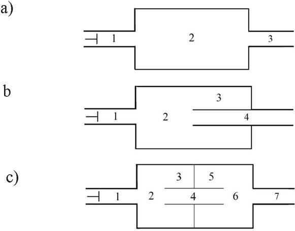
Figure 1 Schematic of analysed dampers: (a) a single chamber damper, (b) a damper with an internal choke tube and (c) a damper with an internal baffle and a choke tube.
The following transfer matrices describe the specified types of dampers:
• A single chamber damper:
| (17) |
• A damper with an internal choke tube:
At the branch junction:
| (18) | ||
| (19) |
The point impedance for the side branch tube:
| (20) |
From the branch side condition it is obtained:
| (21) | ||
| (22) |
In matrix form:
| (23) |
Thus, combining all equations, the transfer matrix for a damper with a choke tube is:
| (24) |
• A damper with an internal baffle and a choke tube:
| (25) |
For the known and the open end boundary condition any damper geometry may be described as follows:
| (26) |
while with the anechoic boundary condition the equations take the form of:
| (27) |
3 Experimental Approach
The test stand for experimental research comprised a single piston air compressor together with an electric motor and an inverter to control the rotational speed. The piston compressor operated in the range of 1000 – 2000 rpm. Air was used as the working medium in the system. Dynamically variable pressure was measured with a system consisting of two industrial pressure transducers along with a signal processing and recording system. The first pressure transducer was mounted on the discharge side of the compressor at the inlet of the damper, while the second one was placed at the outlet of the damper. At the end of the line an opened choke valve was mounted. In the system, the suction and discharge temperatures of the compressor were measured in order to assure the same temperature for each test, which at the beginning of each measurement was 23C. The test stand and a schematic of measurement points are depicted in Figure 2.

Figure 2 Test stand for pressure pulsations measurements under different operating parameters.
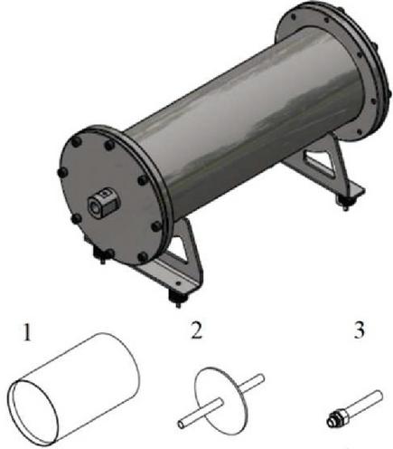
Figure 3 Chamber damper with different internal attenuation elements.
Experimental tests of pressure pulsation were carried out using different configurations of the damper with exchangeable internal attenuating elements. The required volume of the chamber damper was calculated following the Helmholtz resonator theory, by considering the lowest operating speed of the compressor. The chamber damper (Figure 3) was constructed as a cylinder with two demountable flanges with removable internal elements: two sleeves (1) positioning an internal baffle with a choke tube (2) and an internal tube mounted into a flange (3). The internal elements are designed to be mounted in different configurations.
For the current study, three configurations of the damper were used:
• a single chamber damper without internal elements: internal diameter D 200 mm, and chamber internal length L 650 mm,
• a damper with a choke tube: tube length equal to half of the chamber length L3 325 mm and tube internal diameter equal to the internal diameter of the connecting pipe d 24 mm (Figure 4a),
• a damper with an internal baffle and a choke tube: a baffle mounted in the center of a chamber, lengths and diameters identical to those in the second configuration (Figure 4b).

Figure 4 A damper with a choke tube (a) and a damper with internal baffle and choke tube (b) used in the tests.
The tests were carried out for three rotational speeds of the compressor: 1000 rpm, 1500 rpm and 2000 rpm generating different flows of gas. At the end of the line, the opened choke valve was mounted. The static pressure in the system depended on the flow resistance. The measurement cases and operational parameters are listed in Table 1.
Table 1 Measurement cases and operational parameters
| Rotational | Static Pressure | |||
| LC | Damper Type | End Condition | Speed n [rpm] | p [bar] |
| 1 | Chamber damper | Fully opened choke valve | 1000 | 1.53 |
| 2 | 1500 | 2.30 | ||
| 3 | 2000 | 2.93 | ||
| 4 | Damper with an | 1000 | 1.57 | |
| 5 | internal | 1500 | 2.35 | |
| 6 | choke tube | 2000 | 2.87 | |
| 7 | Damper with an | 1000 | 1.50 | |
| 8 | internal baffle | 1500 | 2.27 | |
| 9 | and a choke tube | 2000 | 2.90 |
4 Results
The comparison of the simulation and measurement results was based on the determination of the transmission loss characteristics function (TL), which describes the decrease of the acoustic signal power between the inlet and the outlet of the pulsation damper. A TL graph is usually obtained by using a frequency sweep of the excitation source, microphones for measuring the sound signals and anechoic boundary condition at the end of a test pipe assuring no wave reflections, which in the literature is known as the two-microphone method [11, 13, 14]. In this research a different approach was used. The TL characteristics were obtained individually for each compressor speed by FFT of the damper inlet pressure measured signal divided by FFT of the damper outlet pressure measured signal:
| (28) |
where: and are the Fourier transforms of the pressure-time histories of the incident and the transmitted waves respectively.
For the open pipe condition , the TL function in analytical model was calculated as a ratio of and :
| (29) |
where: is the amplitude of a harmonic volume velocity input and is the amplitude of a harmonic volume velocity output, both of which are a function of frequency.
If the amplitude of the pulsation at the outlet is much greater than the amplitude of the pulsation at the inlet, the TL function reaches the minimum, which indicates the damper resonance – amplification of the pulsation in a given frequency. The maximum of a TL function determines the highest attenuation for a given frequency.
4.1 Analytical Model with Anechoic and Open Pipe Boundary Condition
In Figures 5–7 the comparison between measured and analytical models with boundary conditions of Z=0 and P=0 is presented.
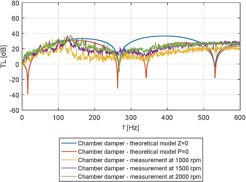
Figure 5 Transmission loss characteristics of a chamber damper.

Figure 6 Transmission loss characteristics of a damper with an internal choke tube.
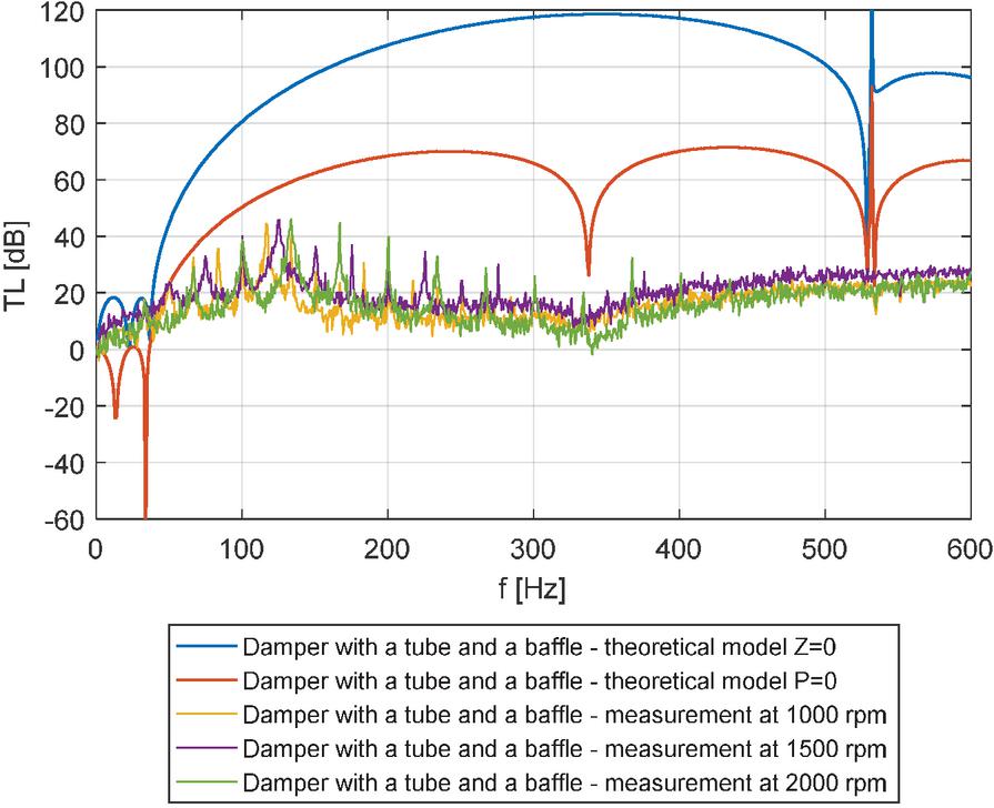
Figure 7 Transmission loss characteristics of a damper with a tube and a baffle.
Analysing the results of the comparison between analytical models and measured data a better agreement may be seen in the case of open pipe boundary condition than an anechoic condition for all analysed damper constructions. The plane wave theory model with boundary condition properly describes the TL functions minima for a chamber damper and a damper with a choke tube at 265 Hz, 342 Hz, 531 Hz. The first minimum of analytical TL functions is related to the resonant frequency of a damper resulting from Helmholtz resonator theory, however, it is not visible in the measurements. The level of attenuation is predicted properly in the case of the first two analysed dampers, however in the case of a damper with an internal baffle and a choke tube (Figure 7), the theoretical transmission loss values are much higher than in the measurements. The analytical model with the assumption of the free flow of gas () at the end of the system indicates the transmission loss function maxima at 266 Hz for a damper with a choke tube and at 533 Hz for a damper with a baffle and a choke tube. This phenomenon results from the mathematical description of closed volumes 3 and 5 (Figures 1b,c) in these types of dampers, which theoretically creates the side branch resonator. In the measurements this phenomenon does not exist for analysed system parameters, and therefore an improvement in the analytical model was proposed.
4.2 An Improved Analytical Model with an Open Pipe Boundary Condition
The proposed changes in the analytical model include a different approach to the closed volumes inside dampers with internal attenuating elements (choke tubes, baffles). In the transfer matrix method, the four-pole matrices describing each system element are multiplied and closed volumes are described as branch tubes with Q at the end (Equations (18)–(24)). The condition of the complete closing of the pipeline means that, the flow pulsation is damped and the wave is fully reflected in the same phase. In the real system, in the authors’ opinion, it is a considerable simplification, as the wave may be reflected only partially. Thus, the authors have proposed some considerations regarding the change in signal analysis in the analytical model.
In the improved model, it is assumed that the flow and pressure wave signals may be added at the cross-section of the internal choke tube, which is graphically depicted in Figure 8.
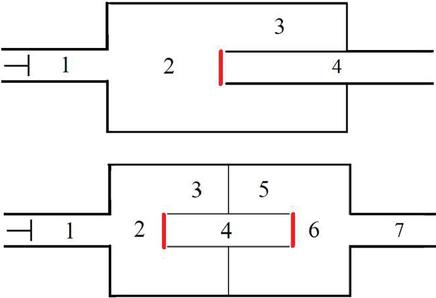
Figure 8 Indication of the surfaces of signals summation.
The transfer matrix for a damper with a choke tube is described as:
| (30) |
where: – – the four pole matrices described by the A, B, C, D coefficients as in Equations (12)–(15).
The damper with a choke tube and a baffle is described as:
| (31) |
In Figures 9 and 10 the results of the comparison between measured data, the standard and the improved analytical models are shown.
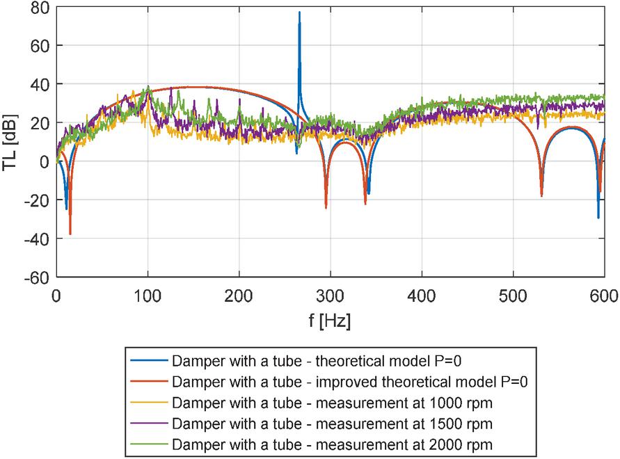
Figure 9 Transmission loss characteristics of a damper with a tube – a comparison with the improved analytical model.
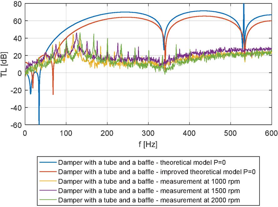
Figure 10 Transmission loss characteristics of a damper with a tube and a baffle – a comparison with the improved analytical model.
5 Conclusions
In the research, the problem of determining the transmission loss characteristics of passive pressure pulsation dampers, with consideration to the boundary conditions of the system was investigated. The geometrical parameters of the dampers in connection with the operating and boundary conditions have an impact on the change in the transmission loss characteristics which is invisible in the standard acoustic method of measurements (such as the two-microphone method). The analytical method based on the plane wave theory is still widely used in fluid systems in order to describe pulsation phenomena, because of its simplicity and robustness of calculation, which is important for large systems. In the article, an attempt has been made to change the measurement method and the mathematical description in order to catch the flow phenomena occurring in the real system during operation. The changes in the analytical model assume that the wave signals in the inlet and outlet surfaces of the internal choke tubes of dampers may interfere and strengthen to some extent, and therefore the summation of signals from the damper flange side and closed volume inside a damper is proposed. That approach improves the agreement between the model and the measurements especially in the case of closed volumes in a damper construction, eliminating the theoretical side branch resonator effect. Further research will concern the considerations regarding the ratio of the transmitted and reflected waves in the analyzed point, i.e. at the open ends of choke tubes.
References
[1] Vacca A, Klop R, Ivantysynova M. A numerical approach for the evaluation of the effects of air release and vapour cavitation on effective flow rate of axial piston machines. Int J Fluid Power 2010;11:33–45. https://doi.org/10.1080/14399776.2010.10780996.
[2] Soedel W. Sound and Vibrations of Positive Displacement Compressors. CRC Press; 2007.
[3] Fiebig W, Wrobel J. System approach in noise reduction in fluid power units. BATH/ASME 2018 Symp. Fluid Power Motion Control. FPMC 2018, American Society of Mechanical Engineers (ASME); 2018. https://doi.org/10.1115/FPMC2018-8855.
[4] Macor A, Rossetti A, Scamperle M. Prediction of sound pressure level for a dual-stage hydromechanical transmission. Int J Fluid Power 2016;17:25–35. https://doi.org/10.1080/14399776.2015.1120137.
[5] Kojima E. Development of a quieter variable-displacement vane pump for automotive hydraulic power steering system. Int J Fluid Power 2003;4:5–14. https://doi.org/10.1080/14399776.2003.10781161.
[6] Klop R, Ivantysynova M. Investigation of noise sources on a series hybrid transmission. Int J Fluid Power 2011;12:17–30. https://doi.org/10.1080/14399776.2011.10781034.
[7] Selamet A, Lee IJ, Huff NT. Acoustic attenuation of hybrid silencers. J Sound Vib 2003;262:509–27. https://doi.org/10.1016/S0022-460X(03)00109-3.
[8] Earnhart NE, Cunefare KA. Compact helmholtz resonators for hydraulic systems. Int J Fluid Power 2012;13:41–50. https://doi.org/10.1080/14399776.2012.10781045.
[9] Poirier B, Maury C, Ville JM. The use of Herschel-Quincke tubes to improve the efficiency of lined ducts. Appl Acoust 2011;72:78–88. https://doi.org/10.1016/j.apacoust.2010.09.010.
[10] Zhou W, Kim J, Soedel W. New iterative scheme in computer simulation of positive displacement compressors considering the effect of gas pulsations. J Mech Des Trans ASME 2001;123:282–8. https://doi.org/10.1115/1.1362320.
[11] Barbieri R, Barbieri N. Finite element acoustic simulation based shape optimization of a muffler. Appl Acoust 2006;67:346–57. https://doi.org/10.1016/j.apacoust.2005.06.007.
[12] Mehdizadeh OZ, Paraschivoiu M. A three-dimensional finite element approach for predicting the transmission loss in mufflers and silencers with no mean flow. Appl Acoust 2005;66:902–18. https://doi.org/10.1016/j.apacoust.2004.11.008.
[13] Tsuji T, Tsuchiya T, Kagawa Y. Finite element and boundary element modelling for the acoustic wave transmission in mean flow medium. J Sound Vib 2002;255:849–66. https://doi.org/10.1006/jsvi.2001.4189.
[14] Liu B, Feng J, Wang Z, Peng X. Attenuation of gas pulsation in a reciprocating compressor piping system by using a volume-choke-volume filter. J Vib Acoust Trans ASME 2012;134. https://doi.org/10.1115/1.4006234.
[15] Panigrahi SN, Munjal ML. A generalized scheme for analysis of multifarious commercially used mufflers. Appl Acoust 2007;68:660–81. https://doi.org/10.1016/j.apacoust.2006.09.005.
[16] Yasuda T, Wu C, Nakagawa N, Nagamura K. Studies on an automobile muffler with the acoustic characteristic of low-pass filter and Helmholtz resonator. Appl Acoust 2013;74:49–57. https://doi.org/10.1016/j.apacoust.2012.06.007.
[17] Lee JW. Optimal topology of reactive muffler achieving target transmission loss values: Design and experiment. Appl Acoust 2015;88:104–13. https://doi.org/10.1016/j.apacoust.2014.08.005.
[18] Chang YC, Chiu MC, Huang SE. Numerical analysis of circular straight mufflers equipped with three chambers at high-order-modes. Appl Acoust 2019;155:167–79. https://doi.org/10.1016/j.apacoust.2019.05.021.
[19] Gaonkar CD, Rao DR, Kumar KM, Munjal ML. End corrections for double-tuning of the same-end inlet-outlet muffler. Appl Acoust 2020;159:107116. https://doi.org/10.1016/j.apacoust.2019.107116.
[20] Jia X, Liu B, Feng J, Peng X. Attenuation of gas pulsation in the valve chamber of a reciprocating compressor using the Helmholtz resonator. J Vib Acoust Trans ASME 2014;136. https://doi.org/10.1115/1.4027790.
[21] Kadam P, Kim J. Experimental formulation of four poles of three-dimensional cavities and its application. J Sound Vib 2007;307:578–90. https://doi.org/10.1016/j.jsv.2007.06.048.
[22] Wang CN, Wu CH, Wu TD. A network approach for analysis of silencers with/without absorbent material. Appl Acoust 2009;70:208–14. https://doi.org/10.1016/j.apacoust.2007.12.006.
[23] Selamet A, Radavich PM. The effect of length on the acoustic attenuation performance of concentric expansion chambers: An analytical, computational, and experimental investigation. SAE Tech Pap 1995;201:407–26. https://doi.org/10.4271/950544.
Biographies

Urszula Warzyńska – assistant professor at the Faculty of Mechanical Engineering at Wrocław University of Science and Technology, received her Ph.D. degree in Mechanical Engineering in 2017. Main research interests include numerical modelling of fluid flow phenomena with thermal and wave effects. From the beginning of her professional career associated with the Faculty of Mechanical Engineering, combining research with participation in commercial projects conducted for business entities. Coauthor of two patent solutions. Author or coauthor of over 50 scientific works, including scientific articles, R&D work overviews, book chapters and conference papers. Since 2020 co-editor of conference proceedings of International Scientific and Technical Conference “Hydraulic and Pneumatic Drives and Controls” (NSHP) held cyclically in Poland. Board member of the Polish Association of Mechanical Engineers and Technicians (SIMP). Educator teaching courses for students at the Faculty of Mechanical Engineering.

Tomasz Siwulski – assistant professor at the Faculty of Mechanical Engineering at Wroclaw University of Science and Technology. Since the beginning of his professional career investigating a broad spectrum of problems relating to heavy engineering machinery. He has held the position of an independent design engineer in a large mining machinery production plant, and as an expert witness provided factual support to the judiciary for over 14 years. Head of several R&D projects conducted in collaboration with industry, resulting in the development and partial implementation of new technical solutions and 5 granted patents. Author and coauthor of over 60 scientific works, including scientific articles, R&D work overviews, book chapters and conference papers. Moreover, author of over 50 forensic analyses. Board member of the Polish Association of Mechanical Engineers and Technicians (SIMP) and member of the Polish Committee for Standardization, KT 160 for Hydraulic Drives and Controls. Educator developing and teaching several courses for students at the Faculty of Mechanical Engineering.
International Journal of Fluid Power, Vol. 21_3, 363–382.
doi: 10.13052/ijfp1439-9776.2134
© 2020 River Publishers