Study on the Articulated Finger Based on Pneumatic Soft Joint
Kai Shi1,*, Huayi Zheng2, Jun Li1 and Gang Bao1
1Pneumatic Center, Harbin Institute of Technology, Harbin, China
2Beijing Institute of Precision Electromechanical Control Equipment, Beijing, China
E-mail: mokenali@foxmail.com
*Corresponding Author
Received 06 December 2020; Accepted 10 March 2021; Publication 29 May 2021
Abstract
This article described a novel pneumatic soft joint used to make articulated soft fingers. This soft joint was designed by improving the basic structure of the fast pneumatic network. The joint was made of high modulus E630 silicon, which can increase the reverse exhaust speed through its high structural elasticity. Aramid fabric was used to restrain the non-working direction of joints to reduce ineffective expansion, thereby reducing air consumption. The kinematics and statics model of the joint was established by the piecewise constant curvature (PCC) method, and the model was proved to be effective. The silicone staging pouring process was used in the manufacture of joints and fingers, which can achieve high-quality product rates. A soft finger actuator composed of three soft joints was designed and manufactured, whose length was 1.3 times the human finger. The finger can nimbly achieve the target motion, and the gripping force of the fingertip can reach 7.1N. The articulated soft finger actuator has applications in soft dextrous hands and soft gripper.
Keywords: Soft joint, pneumatic, finger actuator, silicon.
1 Introduction
In recent years, Soft robot technology has evolved rapidly due to its soft structure and strong adaptability. Soft dexterous hands are one of the typical applications of soft robot technology. The basis of soft dexterous hand is a soft finger, and there are many types of soft fingers have been developed.
Cable-driven is a common solution. Manti et al. (2015) proposed the Bioinspired Soft Robotic Gripper that is based on the control of a single cable tension. The soft gripper is divided into soft part and hard part through the structure and constraint design, and the soft part corresponds to finger joint. By pulling the hard part through the cable, the soft part will bend to compensate for the change of the length of the cable, so as to simulate the bending process of the finger. The Soft Bionics Hands that was designed by Tavakoli et al. (2017) also used a similar working principle. In addition, Mutlu et al. (2016) designed The Soft Monolithic Prosthetic Fingers that was manufactured by 3D printing technology.
The Pneumatic Network that was proposed by Shepherd et al. (2011) is another common actuator. In this actuator, a plurality of airbags is fixed on a base layer that is difficult to extend but easy to bend. When the airbags inflate, the airbags push each other, and the length of the side of the airbags extends. At the same time, the length of the base layer has not changed, the length difference between the airbags layer and the base layer causes the actuator bending. For example, Polygerinos et al. (2014) proposed the soft pneumatic glove that is an application of the fast pneumatic network, and Hao et al. (2016) proposed the soft pneumatic robotic gripper that is also based on the pneumatic networks. Other soft fingers that are based on the pneumatic networks include the Miniature Pneumatic Curling Rubber Actuator which is designed by Wakimoto et al. (2011) and the modular soft robotic gripper which is designed by Homberg et al. (2015).
Fiber restraint schemes are also very common. Winding constraint fiber outside the parallel cavities, and then the bending is realized by controlling the pressure difference of different cavities. Such as the Multi-Chambers Flexible Actuator that is designed by Fang (2017). Another fiber restraint soft actuators have single chamber, they could achieve bending by one side constraint and the chamber should be confined to expansion through winding fiber. Such as the Opto-electronically innervated soft prosthetic hand which is designed by Zhao et al. (2016) and the BCL-26 hand that is designed by Zhou et al. (2019).
The Bionic Soft Hand is designed by FESTO company (2018) that adopts the bellows and external constraint fabric. When the bellows inflating, the bellows will bend under the constraint of the fabric gloves that set the bending direction.
After combining the above several schemes, the PN unit is improved based on the PN structure, and a soft joint using Kevlar fabric for expansion and bending constraints is proposed. The design and fabrication of a new type of soft finger are based on the soft joint and the finger will be used to the soft robotic hand. The main research contents of this paper include: the structure of the soft joint and soft finger; the fabricating process of the soft finger; kinematic and static modeling of fingers and their experimental verification.
2 Design and Fabrication
2.1 Design
Mosadegh et al. (2014) has put forward a fast pneumatic network that can actuate more rapidly than the normal pneumatic networks (Shepherd et al. 2011), in which every airbag is independent and don’t share the same wall. Therefore, when the airbag expanding, the air consumption is small and the speed is fast. Based on the fast pneumatic network structure, we improved and designed a soft joint, whose structure is shown in Figure 1.
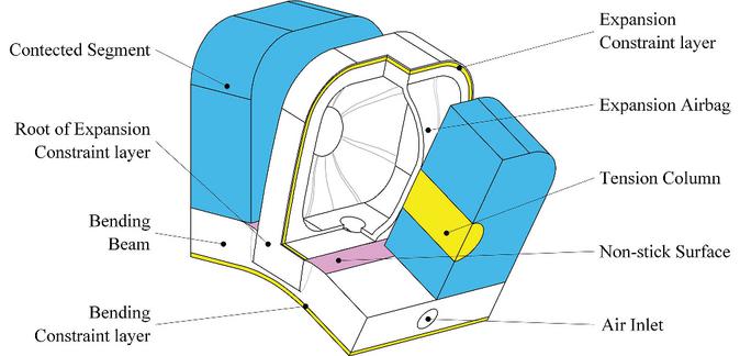
Figure 1 Structure of soft joint.
In order to increase the bending angle, we use a thinner bending beam, but this design reduces the elastic recovery ability of the joint, so we design the tension column structure to make up for the loss of the elastic recovery ability. In order to limit the unnecessary deformation of the airbag, we adopt the lateral expansion constraint layer to reduce the lateral expansion.
We will design and fabricate a soft finger by this soft joint and we need three joints. Considering the difference of load conditions and appearance, there will be some differences in the sizes of the three joints. The main same sizes of the different joints are shown in Figure 2.
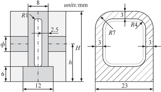
Figure 2 Size of soft joint.
The joint height, the diameter and position of the tension column of the three soft joints are designed to be different, and the differences of the sizes are shown in Table 1.
Table 1 Different sizes of the different soft joints
| Joint | Height (H) | Diameter () | Position(h) |
| Tip | 28 mm | 6 mm | 15 mm |
| Middle | 26 mm | 6 mm | 14 mm |
| Root | 24 mm | 5 mm | 13 mm |
The structure and sizes of the soft finger based on the aforementioned soft joint are shown in Figure 3. From left to right, the structure is finger tip, finger tip joint, finger middle, finger middle joint, finger root and finger root joint. The size of soft fingers refers to the size of each part of the author’s index finger and is enlarged by 1.3 times. The size has been indicated in Figure 3.

Figure 3 Structure and sizes of soft finger.
2.2 Fabrication
The fabrication of the soft finger is complex and difficult. We have designed and found a set of fabrication technology of soft finger through a multitude of trials, and the fabrication process is shown in Figure 4.
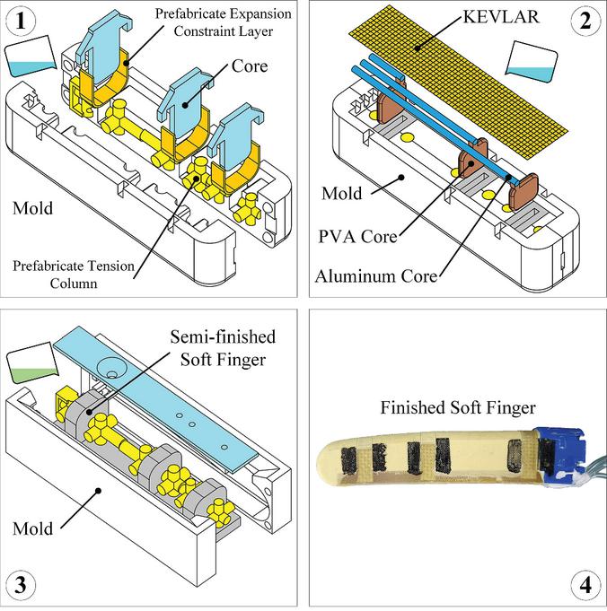
Figure 4 Manufacturing method of soft finger.
This fabrication process adopts silicone staging pouring process, as follows:
(1) Manufacture of airbags and tension columns:
Place the prefabricated tension columns into the mold, then assemble them and seal the mold with a stretch film. After the assembly is completed, the expansion constrained layers are placed in the specified position in the mold, and the corresponding inner cores are inserted. Then, E630 silicone rubber manufactured by Shenzhen Hongye Company is injected. The silicone rubber needed to be vacuum defoamed before pouring. In this process, silicone rubber only needed to be injected onto the surface of the platform. After the above steps are completed, the mold should be put at room temperature for at least 4 hours to make the silicone rubber cured. The prefabricated tension columns are made of E630 silicone rubber and broken Kevlar fiber in a special mold, and the expansion constraining layers are made of E630 silicone rubber coated on Kevlar fabric.
(2) Manufacture of constraint layer:
Remove the inner cores that are assembled in the previous process, and insert the PVA water-soluble inner cores into the vacant position. Use soft aluminum rods to make the flow-paths, here they are only used as straight flow-paths. In fact, the soft aluminum rod can be used as a curved flow-path, and under a certain external force, it can be pulled out of the curved silicone flow-path. Use PVA liquid glue to glue one end of the soft aluminum rod to the PVA water-soluble inner core, and place the other side on the positioning groove of the mold. In the next operation, we need to inject the vacuum-defoamed E630 silicone rubber onto the top of the mold, and finally put the cut Kevlar fiber fabric used as a bending constraint on the silicone rubber to keep it at room temperature for 4 hours to cure.
(3) Encapsulation and shaping:
Disassemble the mold, take out the semi-finished soft finger, then apply PVA liquid glue on the expansion surface and non-stick surface of each soft joint, then put into the shaping mold, pour in 640 silicon rubber, and let it stand at room temperature until it is solidified.
With this fabrication process, soft fingers which could be used normally would be manufactured.
3 Modeling
The Piece-wise constant curvature method (PCC) is usually used in the modeling of the soft robot (Hannan et al. 2003, Marchese et al. 2014). The bending of the soft joint is similar to the arc so that the kinematic model of the soft finger was considered to be built based on the PCC method. In this process, the constraint layer of each soft joint is considered to be curved with a constant curvature arc, and the connecting segment is treated as a rigid body. The coordinate systems on the connecting lines between the joints and segments on the constraint layer are established, and the kinematics and statics are analyzed as shown in Figure 5.
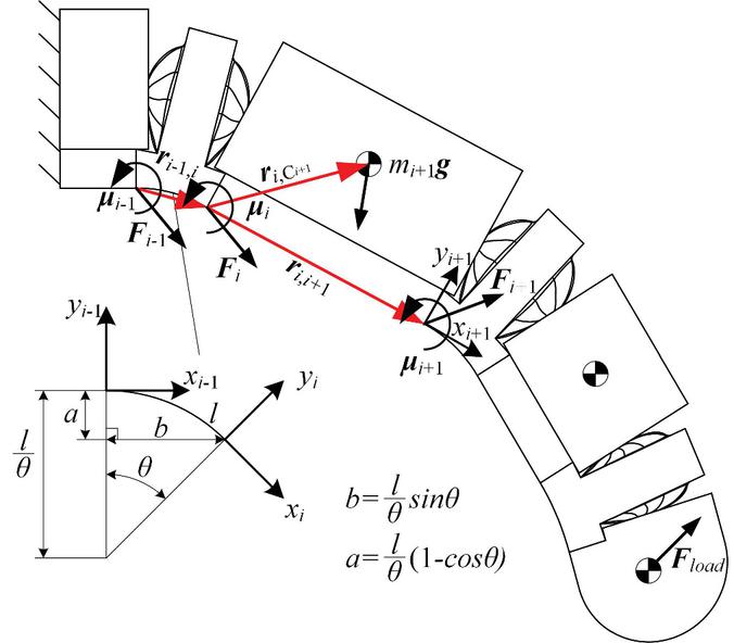
Figure 5 Kinematics and statics analysis of soft finger.
The bending angle of a joint is set to , and the arc length of the curved layer is set to l. Therefore, the position of the origin of the coordinate system which is far from the finger root can be calculated as shown in Equation (1), and the position coordinates are defined in the coordinate system close to the finger root.
| (1) |
On this basis, the transformation matrix of the two coordinate systems which are located in the both sides of the joint is shown in Equation (2).
| (2) |
The deformation of the segment is small and negligible, therefore the segment is considered as a rigid body to transmit force. Compare with the mass of the segment, the mass of the joint is small, and it is assigned to the connecting segments on both sides. Therefore, the force transfer equation could be obtained as shown in Equation (3).
| (3) |
The force transfer process of the soft joint part no longer considered the influence of the gravity, and it is shown in Equation (4).
| (4) |
The length of the position vector changes with the bending angle of the joint, its expression can be written as shown in Equation (5) when it is relative to the coordinate system .
| (5) |
After that, the calculation of kinematics and statics can be carried out by means of coordinate transformation and recursion. In addition, the parameters of mass and centroid position that will be used later are shown in the Table 2. The centroid coordinate is defined relative to the coordinate system outside the soft joint like as the coordinate system which is shown in Figure 5 when the all bending angles are zero.
Table 2 Mass and centroid position
| Segment | Mass | X-coordinates | Y-coordinates |
| Tip | 16.59 g | 6.51 mm | 12.09 mm |
| Middle | 23.30 g | 9.86 mm | 13.59 mm |
| Root | 40.75g | 20.09 mm | 14.32 mm |
4 Experiment
In order to test the performance of soft fingers and verify the model of soft fingers, we designed a press experiment to measure the contact force between the soft finger and a plane. The measuring method and device are shown in Figure 6.
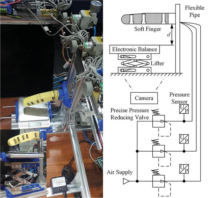
Figure 6 Measuring device of contact force of the soft finger, the left figure shows the measuring device and the right figure shows the measuring method.
4.1 Verification of Kinematics
This device consists of a pneumatic loading system (which composed of air supply, pressure reducing valves, pressure sensors and gas pipe), a self-locking lifter, an electronic balance, and a camera. Adjust the height of the lifter to a set value, and apply different pressures to the three joints of the soft finger to bend it. The crooked finger will be in contact with the electronic balance on the lifter, so that we could get the contact force between the soft finger and the electronic balance through read the display on the electronic balance. At the same time, we can photograph the bending state through the camera, so that three bending angles will be obtained by later measurement.
We will conduct a set of experiments to get the contact forces at different pressures and different positions. A group of pressures which include 0.1 bar, 0.5 bar, 0.9 bar and 1.3 bar are applied to the fingertips. A group of pressures which include 0.1 bar, 0.4 bar, 0.7 bar and 1.0 bar are applied to the middle part and root part of the finger. The distance (d shown in Figure 6) between the measuring surface of the electronic balance and the lowest part of the finger root are set as 39 mm, 61 mm and 81.6 mm. We can use the previous PCC model to calculate the theoretical distance by the bending angles and sizes of the Soft Finger , so that the accuracy and applicability of the PCC model could be verified by comparing theoretical and practical distances.
This theoretical and practical distance are taken as the ordinate, and the corresponding contact force is taken as the abscissa, the comparison result is shown in Figure 7.
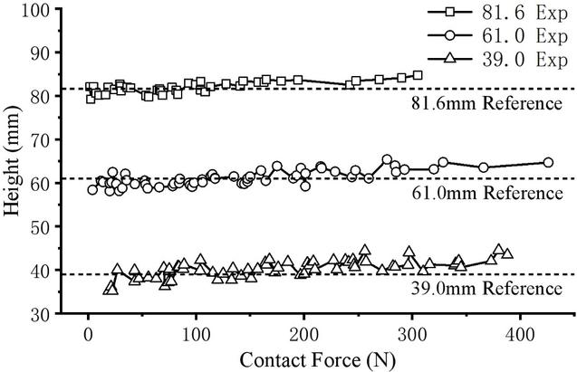
Figure 7 Verification of kinematics, theoretical and practical distances are compared to demonstrate the accuracy and applicability of the PCC model.
Analyze the data shown in Figure 7, we think the Piece-wise constant curvature method can be used to model the displacement kinematics. Meanwhile, when the contact force is large, the calculated distance is larger than the practical reference distance, which may result in the deformation of the segment or the joint bending that is not arc-shaped.
4.2 Static Characteristics of the Soft Joint
Next, the static model will be verified, but first, the output moments of the joints should be got. The soft joint has a complex structure and characteristics so that it’s hard to get its mechanical constitutive relation by common modeling method. The experimental method to obtain the relationship between output moment, angle and the internal pressure of the airbag would be adopted to get the characteristic of the soft joint.
In order to obtain this relationship, there are generally two methods: in the first method, we will get the angle by changing the input moment load while the pressure is fixed (Mutlu et al. 2016). In the second method, we will get the output moment by changing the internal pressure while the angle is fixed (Fan et al. 2020).We usually get the angle by photographing method in the field of soft robot research, but it’s very tiring to use photographing method and there are a large number of angle data should be dealt in the first test method. Meanwhile the input moment is hard to load at regular spacing, therefore we decide to adopt the second method.
We will adjust the joint angle to the set point and fix the joint by magnetic base, then we give the joint compressed air at different pressures. Under the action of air pressure, the output force will be obtained after the joint presses the force sensor. The output moment could be calculated by multiplying the force times the moment arm. The principle of the experimental measuring device is shown in Figure 8.
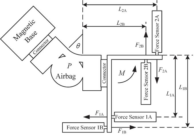
Figure 8 The principle of the measuring device.
The magnetic base is used to fix the Joint, the A-Group of sensors and moment arms are used to measure the positive output moment, and the B-Group are used to measure the negative output moment. The calculation formula of the output moment is is shown as Equation (6).
| (6) |
The physical version of the measuring device is shown in Figure 9, and the main parts are manufactured by 3D printing. The A -Group and B-Group of sensors is the same group actually, the measurement group is switched by changing the installation position.

Figure 9 Measuring device of static characteristics of the soft joint.
We tested the static characteristics of the soft finger and obtained the relationship between output torque, Angle and internal pressure of the airbag by the previous device. The static characteristics of the three different joints of the finger are shown in Figure 10.
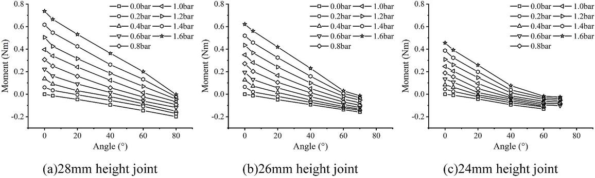
Figure 10 Static characteristics of the soft joint, from left to right, there are 28 mm, 26 mm and 24 mm high joints.
As shown in Figure 10, in the static characteristics curve of the 28 mm an d 26 mm high joints, the moment and the angle show good linearity, and it has good piecewise linearity between the moment and the angle in the curve of the 24 mm high joint. In general, the higher joint has the larger action area of the airbag, and the larger moment output.
On the basis of the experimental data of these characteristics, the output moment of the joint which is not easy to measure can be estimated by the linear interpolation method using the easily measured angle and the internal pressure of the air bag.
4.3 Verification of Statics
Using the previous experiments data, the contact force and joint angle can be substituted into the static recurrence model, and the theoretical moment of each joint can be obtained. Draw the calculated static moment as the abscissa and the interpolation moment as the ordinate, and compare it with the 45 reference line (ordinate = abscissa), as shown in Figure 11.
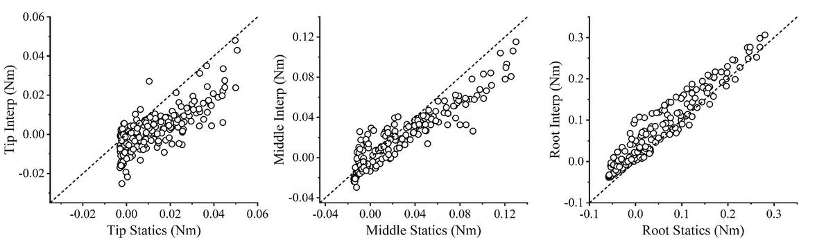
Figure 11 Verification of statics.
Due to various errors (including measurement error and model error), there are certain deviations in the static moment and the interpolation moment. The Moment of the fingertip is small relatively, and its error is more obvious. However, the overall trend of the data shows that the static moment is still close to the interpolation moment. The Moment of the other two joints is larger relatively, at this time, the data point is closer to the 45 reference line, and the statics moment and interpolation moment are relatively close. Therefore, we can think that the static recurrence model has certain accuracy, and the dynamic model based on it also has certain accuracy.
When the pressures of the three joints are 1.86 bar, 1.43 bar, and 1.48 bar respectively, the contact force output of the soft fingers reached 7.1 N.
5 Conclusion
The FPN structure is suitable to be a soft joint, so a single unit is extracted from the FPN structure to improve the design. Under the condition of ensuring the bending ability of the unit, the spring-back ability of the uint is improved by ingenious structural design and the improved FPN uint can be regarded as an independent soft joint control unit. In this way, the FPN actuator with continuous deformation becomes a soft finger with controllable joints. The soft finger is driven by compressed air and can achieve high force output (7.1N), so it is possible to complete light load tasks.
The structure, fabrication technology, and modeling method of the soft finger were studied. Based on the staging pouring process, the physical realization of the soft finger is completed, which can be used for further experiments and research. The Piece-wise constant curvature method is introduced to establish the kinematics and statics model of the soft finger. The experimental results show that the Piece-wise constant curvature method can be used to establish the soft finger model, which will provide guidance for further research on soft finger modeling and control.
After that, we will continue to establish the theoretical model of the soft joint to optimize the structure of the soft finger, and build a more detailed model for simulation and control, design a sensor suitable for the finger, and implement servo control. We will combine soft fingers into soft dexterous hands for complex light-load operation.
References
BionicSoftHand: Pneumatic robot hand with artificial intelligence, 2019. https://www.festo.com.cn/group/zh/cms/13508.htm
Fang, F., 2017. Research On Multi-Chambers Flexible Actuator. Harbin Institute of Technology.
Fan, J., et al., 2020. Experimental Study on Frog-inspired Swimming Robot Based on Articulated Pneumatic Soft Actuator. Journal of Bionic Engineering, 17(2), 270–280.
Hannan, M. W. and Walker, I. D., 2003. Kinematics and the implementation of an elephant’s trunk manipulator and other continuum style robots. Journal of robotic systems, 20(2), 45–63.
Homberg, B. S., et al., 2015. Haptic identification of objects using a modular soft robotic gripper. IEEE International Conference on Intelligent Robots & Systems, pp. 1698–1705.
Manti, M., et al., 2015. A bioinspired soft robotic gripper for adaptable and effective grasping. Soft Robotics, 2(3), 107–116.
Tavakoli, M., et al., 2017. Soft bionics hands with a sense of touch through an electronic skin. Soft Robotics: Trends, Applications and Challenges, pp. 5–10.
Mutlu, R., et al., 2016. Mechanical stiffness augmentation of a 3D printed soft prosthetic finger. 2016 IEEE International Conference on Advanced Intelligent Mechatronics (AIM), pp. 7–12.
Mutlu, R., et al., 2016. 3D printed flexure hinges for soft monolithic prosthetic fingers. Soft Robotics, 3(3), 120–133.
Hao, Y., et al., 2016. Universal soft pneumatic robotic gripper with variable effective length. Chinese Control Conference, pp. 6109–6114.
Mosadegh, B., et al., 2014. Pneumatic networks for soft robotics that actuate rapidly. Advanced Functional Materials, 24(15), 2163–2170.
Marchese, A. D., et al., 2014. Design and control of a soft and continuously deformable 2D robotic manipulation system. IEEE International Conference on Robotics and Automation, pp. 2189–2196.
Polygerinos, P., et al., 2014. Towards a soft pneumatic glove for hand rehabilitation. International Conference on Intelligent Robots and Systems, pp. 1512–1517.
Shepherd, R. F., et al., 2011. Multigait soft robot. Proceedings of the National Academy of Sciences, 108(51), 20400–20403.
Wakimoto, S., et al., 2011. Miniature pneumatic curling rubber actuator generating bidirectional motion with one air-supply tube. Advanced Robotics, 25(9–10), 1311–1330.
Zhao, H., et al., 2016. Optoelectronically innervated soft prosthetic hand via stretchable optical waveguides. Science Robotics, 1(1), 1–10.
Zhou, J., et al., 2019. A soft-robotic approach to anthropomorphic robotic hand dexterity. IEEE Access, 7, 101483–101495.
Biographies

Kai Shi was born in 1990. He received the BSE degree in 2014 and the MSME in 2016 from Harbin Institute of Technology. He is studying towards his Ph.D. in the area of fluid-driven soft robot at Harbin Institute of Technology.

Huayi Zheng was born in 1978. He received the BSE degree in 2001 and the MSME in 2004 from Beihang University. He currently works at the Beijing Institute of Precision Electromechanical Control Equipment and he served as the project leader. His research activities are fluid and mechanical transmission, servo control technology.

Jun Li was born in 1972. He received the M.S. and Ph.D. degrees in mechanical engineering in Harbin Institute of Technology, China, in 1995 and 1999, respectively. From 2001 to now, he is an Associate Professor at Harbin Institute of Technology. His research activities are fluid-driven soft robot, physical simulation experiment systems.

Gang Bao was born in 1960. He received the M.S. and Ph.D. degrees in mechanical engineering in Harbin Institute of Technology in 1986 and 1992, respectively. He is the dean of Pneumatic Center of Harbin Institute of Technology. His research activities are pneumatic components and systems, physical simulation experiment systems, and virtual assembly technology.
International Journal of Fluid Power, Vol. 22_2, 277–292.
doi: 10.13052/ijfp1439-9776.2226
© 2021 River Publishers