Influence of Air Dissolved in Hydraulic Oil on Cavitation Erosion
Sven Osterland*, Lutz Müller and Jürgen Weber
Chair of Fluid-Mechatronic Systems (Fluidtronics) – Technische Universität Dresden, Germany
E-mail: Sven.Osterland@tu-dresden.de; Lutz.Mueller@tu-dresden.de; Juergen.Weber@tu-dresden.de
*Corresponding Author
Received 03 February 2021; Accepted 12 July 2021; Publication 29 July 2021
Abstract
This article gives experimentally evidence that cavitation erosion in hydraulic components like valves and pumps is caused by vapour cavitation not gas or pseudo cavitation. In fact, the free air content which is released by vapour and gas cavitation reduces the erosion significantly.
In order to clearly separate the different cavitation types, a test rig with a specially designed reservoir with integrated degassing capability is presented. As flow geometry a valve model with realistic dimensions and under realistic operating conditions was used, which ensures very high transferability of the results to the reality of hydraulic components in practical applications and typical operating conditions.
A total of 4 five-hour long tests are performed and analysed. The quantification of the cavitation erosion is determined by the mass loss of the copper samples. The experimental results show a 4.4–5.1 times higher mass loss in tests with air-free oil compared to tests with air-saturated or oversaturated hydraulic oil.
The experimental fact that air-free hydraulic oil causes significantly more cavitation erosion than normal (saturated) hydraulic oil, and its implications are discussed. The conclusion can be drawn, that further developments of hydraulic components and systems towards the use of air-free oil or increasing power densities will be disproportionately challenged by cavitation erosion.
Keywords: Cavitation erosion, vapour cavitation, gas cavitation, air-free oil, cavitation in hydraulic pumps and valves.
1 Introduction
Cavitation is the formation, oscillation and decay of cavities in liquids. Accordingly, vapour cavitation is the evaporation and re-condensation of liquid to vapour due to local pressure variations which go below the vapour pressure. In contrast, gas cavitation is the desorption, oscillation and dissolving of gas bubbles in a liquid as a result of local pressure variations going below the saturation pressure of the liquid. During the operation of hydraulic systems, the occurrence of cavitation is usually unavoidable [1]. Vapor and gas cavitation are based on two completely different physical processes and work on different physical time scales. Vapour cavitation is a phase transition and gas cavitation is a diffusion process. In nano- or microseconds vapour bubbles re-condensate and collapse in regions of higher pressure which can cause an erosive micro jet. Air bubbles do not re-condensate but diffusively resolve in the liquid, which takes seconds or minutes. Therefore, air bubbles usually do not collapse and cause no micro jet. The effect of cavitation fundamentally limits the operating range, the lifespan and performance of hydraulic components and systems.
Because mineral oil contains high amounts of air (e.g.100 L HLP46 contain 7 to 10 L of air at STP), a distinction is made between vapour, gas and pseudo cavitation. This categorisation is reasonable as the different types of cavitation are based on completely different physical processes and differ in cause and effect.
Table 1 gives an overview of the different cavitation types and their effects. In most hydraulic systems all types occur simultaneously and influence each other.
Table 1 Types of cavitation in hydraulics
| Vapour Cavitation | Gas Cavitation | Pseudo Cavitation | |
| Physical process | Phase change (evaporation and condensation) Mass exchange between liquid and gaseous phase | Degassing or diffusion process Mass exchange between free and dissolved gases (e.g. air) | Pressure-dependent density and thus volume change of the gas bubbles No mass exchange |
| Cause | Abrupt formation of vapour bubbles as soon as the pressure falls below the vapour pressure Abrupt condensation and implosion as soon as the pressure rises above the vapour pressure | Continuous outgassing as soon as the pressure falls below saturation pressure Slow and continuous resolving of free gases as the pressure rises above saturation pressure | Presence of free gas Local pressure change in the flow Compressibility of the gas (e.g. ideal gas law) |
| Major effects | Noise emission Pressure losses Cavitation erosion damage caused by micro-jets due to imploding bubbles | Filling losses of pumps Oil ageing by oxidation (diesel effect) Reduction of the system stiffness (low compression modulus) Damage to sealing Damping of cavitation erosion | Filling losses of pumps Oil ageing by oxidation (diesel effect) Reduction of the system stiffness (low compression modulus) Damage to sealing Damping of cavitation erosion |
This paper focuses on the aspect of cavitation erosion.
The damage mechanism of cavitation erosion has been well researched on the medium water already. As soon as the local pressure falls below the vapour pressure and cavitation nuclei are present, parts of the liquid evaporate and condense again abruptly as soon as the bubbles enter areas of higher pressure. The bubble dynamics that describe the process are characterised by complex interactions, non-linearities and instabilities. Particularly relevant for damage is the explosive, asymmetric bubble collapse near the wall illustrated in Figure 1, which can cause very rapid micro-jets at up to 410 m/s, shock waves of 6100 to 9300 bar and temperatures of 5000 K [2]. Such a strong mechanical stress of the material leads to plastic deformations, crack initiation and grow up to material removal. A continuous process of cavitation erosion damages continuously and eventually leads to component failure. The mass loss due to cavitation erosion depends very strongly on the flow velocity and/or pressure drop [3].
| (1) |
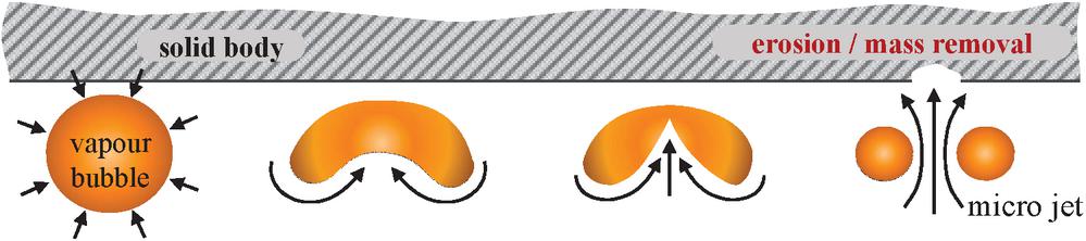
Figure 1 Asymmetrical vapour bubble collapse close to the wall.
In contrast to water, vapour and gas cavitation are usually present in parallel in typical oil hydraulic components [4–7]. The question arises whether vapour or gas cavitation or both are responsible for cavitation erosion in hydraulic components? Until now it was not possible to distinguish both effects from each other and therefore there were different opinions which kind of cavitation, vapour or gas causes cavitation erosion.
The authors of this article argue that most frequently cavitation erosion in hydraulic pumps and valves is caused by vapour cavitation and not by gas cavitation. In fact, concerning the most critical effect of cavitation, the erosion, we expect gas cavitation to reduce the cavitation erosion by damping the damage relevant vapour cavitation.
It should be noted that not all sources agree on the damping effect of gas cavitation on the erosion in hydraulic components. Mainly in the literature concerning oil-hydraulic systems, some sources can be found which claim that gas cavitation is the main reason for cavitation erosion. So this conflict has to be cleared first.
For instance in [8–10] the oil deterioration and the cavitation erosion were examined with focus on gas cavitation. These experiments were long-term tests with a gear pump where the inlet flow was laden with free air with a regulated volume fraction of 8.5%. Within the pump the air bubbles in the flow were stressed with a pressure rise of at least 100000 bar/s which was identified by [10] as the border not only for initiation of the micro-diesel effect but also for a gas-bubble collapse with the characteristic micro-jet causing the erosive damaging of the nearby surface named as “compression-caused erosion”. But [8] clearly wrote that the damages resulting from different flow conditions can be separated in “compression-caused erosion” and “jet caused cavitation”, whereas the damage due to “jet caused cavitation” is of greater significance in oil hydraulic systems.
Vapour cavitation is typical for jet flows, such as those found at throttling points of valves, pump valve plates or combing gear-teeth, in which the otherwise dissolved air is also released [7, 8].
Concluding from these facts already Kleinbreuer [8] resumed that “compression caused (gas) cavitation” can be avoided by design and is of less importance than “jet caused cavitation” which is much more often limiting the operating range.
The question is, if “jet caused cavitation” consist of gas and/or vapour cavitation and how these types of cavitation are interacting. Until now, no sources can be found which experimentally clearly distinguish vapour cavitation from gas cavitation on the issue of cavitation erosion.
The best way to resolve these issues within the fluid power community is by experiments.
For cavitation in water countless experiments have been performed from which some deal with the effect of air on the erosion. For water, it has been shown many times that additionally added air to the flow reduces the erosion e.g. [11–15]. This fact leads even to concepts with air injection to avoid cavitation erosion in water-turbines [16]. The reduction of cavitation erosion by adding additional free air was also observed in hydraulic oil by [8].
On the other hand it has been reported that reducing the amounts of (dissolved) air in water by degassing also decreases the cavitation damage [16]. This is explained by a decreasing number of micro bubbles, which function as cavitation nuclei in the water used in the tests which was from otherwise high purity. Reducing the cavitation nuclei from water leads to a significant reduction of the pressure needed for the vaporisation of the water [17]. Therefore, the intensity of the cavitation erosion in water can be reduced by the reduction of free and dissolved air with degassing below the natural saturation.
Experiments with water, however, cannot simply be applied to mineral oil, as both liquids vary greatly in their chemical and physical properties. For example, the vapour pressure of water is 7381 Pa at 40C [18] whereas the vapour pressure of the used mineral oil is 15.1 Pa at 40C, according to external measurements. Furthermore, mineral oil can dissolve 3–5 times more air then water does. For this reason, gas cavitation and its effect on cavitation erosion is much more relevant for mineral oil than for water. The limited applicability of experiments in water to hydraulic oil requires experiments directly with oil, ideally using a realistic flow regime.
The authors of the article are not aware of any scientific experiments that separate the effects of gas and vapour cavitation on cavitation erosion in hydraulic oil.
In order to close this research gap and solve the dispute about the role of gas cavitation on the erosion damage an experiment in an oil hydraulic valve model is conducted. The valve and test stand were carefully designed to provide scientific access to a valve geometry which is geometrical and fluid-mechanical similar to a real valve, as discussed in [19] and [20]. This test stand provides practically relevant, moderate operating conditions. Therefore, the results of these tests have a very high transferability to real valve flows in practice.
2 Experimental Setup
2.1 Objective and Principles
The aim of the experiment is to quantify the influence of vapour and gas/pseudo cavitation on the cavitation erosion for mineral oil in a realistic hydraulic flow.
Since under normal conditions all cavitation types occur simultaneously, a separation of the effects is necessary. The most effective way to clearly separate the types is to degas the oil completely. This completely suppresses gas and pseudo cavitation, as there is neither free nor dissolved gas in the liquid. Consequently, only vapour cavitation can occur.
Erosion tests with degassed (only vapour cavitation), normal (gas/pseudo and vapour cavitation) and oversaturated (gas/pseudo and vapour cavitation) mineral oil are then carried out and the resulting erosion damage is quantified and compared.
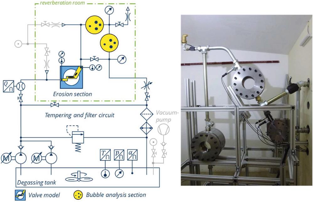
Figure 2 Hydraulic circuit diagram of the entire test rig (left); photo of the erosion section and bubble analysis sections in a reverberation room (right).
2.2 The Test Rig
2.2.1 Overview of the hydraulic system
The test rig shown in Figure 2 is designed for flow and cavitation visualisation and erosion testing and was already described in [20, 21] and [22] in detail. For the current research it is additionally equipped with two bubble analysis sections and, most important, with a carefully designed airtight hydraulic reservoir in which the content of dissolved air in the fluid can be adjusted and measured. Details on the tank and degassing process are given in Section 2.2.2. A standard hydraulic oil HLP46 (Fuchs Renolin B15 VG46) is used as fluid. The kinematic viscosity is and the density is at 40C.
The test rig is supplied by a gear and/or screw pump, each of which is driven by a 20 kW electric servo motor. The maximum permitted pressure is 150 bar.
After passing a volumetric flow sensor the flow enters the valve model, in which the cavitation occurs. At the inlet and outlet of the valve model the pressure and temperature is measured. After leaving the erosion section the flow passes either thought the bypass or into two bubble analysis sections, which are used for the investigation of the cavitation wake. An outlet throttle allows the back pressure in the valve chamber to be regulated. To keep the liquid clean of particles, a 10 m filter is installed in the main flow, which filters 99.75% of 10 m particles and still 96.7% of 5 m particles at each passage [23]. Due to the high flow rate and pressure drop in the valve model, approximately 23 kW of heat is generated. To prevent the oil from heating up and to ensure a constant temperature over the entire duration of the test, the excess heat is removed by a heat exchanger, which is connected to the main cooling circuit of the laboratory.
Of course, the system is protected against overpressure by a pressure relief valve, which can also be used for an initial heat up before the experiments.
The piezo resistive pressure sensors used have a relative measuring error of 0.1%. The temperatures are determined by type K average thermocouples with a measuring accuracy of 1 K. The helical screw flow meter has an accuracy of 0.1 l/min. The precision balance used to determine the loss of mass has a measuring accuracy of 0.1 mg.
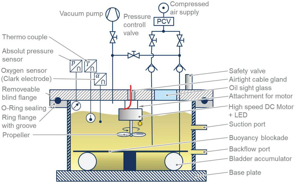
Figure 3 Details on the hydraulic tank, which allows gassing and degassing of the fluid and pressurization; Volume: 113 L; Pressure range: 0.0003–5.0 bar (abs.).
2.2.2 Hydraulic tank with degassing capability
To adjust the content of dissolved air in the mineral oil, a special tank was designed and constructed, as shown in Figure 3. In this way, degassing can take place directly within the hydraulic system, which is preferable to external degassing in order to avoid re-accumulation of air during the re-filling process.
The degassing is done by applying a vacuum of 0.3 mbar to the tank. According the Henry’s law, the gas solubility of liquids is directly proportional to pressure. In other words, 100 L of hydraulic oil, which can dissolve about 10 L of air at one bar, can dissolve up to 50 L at 5 bar but only 0.003 L at 0.3 mbar. Strictly speaking, it is even lower if you consider that the air solubility is already 0 at vapour pressure. This means that solubility can be reduced dramatically by lowering the ambient pressure in the tank. As a result, the oil under vacuum becomes oversaturated and begins to degas. This process alone is very slow and it would take days or weeks until the whole tank is completely air-free. To accelerate the degassing process a DC-motor with an attached propeller is activated. The resulting circulation and shear stresses introduced into the liquid allow complete degassing within hours.
Before using the degassed fluid, the vacuumed tank needs to be re-pressurized. To avoid contact between air and the air-free oil, a bladder accumulator is inflated until the desired tank pressure is reached.
The tank is equipped with a pressure, temperature and dissolved oxygen sensor. The oxygen sensor works on the basis of the Clark electrode, where the dissolved oxygen reacts to a cathode, which emits a very small current directly proportional to the oxygen concentration. The measurement of the oxygen concentration in itself is proportional to the air content, as Henry’s law also applies to nitrogen and all other gasses which air is containing.
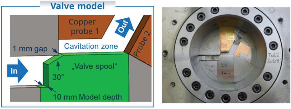
Figure 4 Flow geometry based on a hydraulic spool valve with copper erosion samples; Probe 1 showed significant erosions; Probe 2 showed only little erosion and is not analysed.
2.2.3 The flow geometry
Typical hydraulic components where cavitation erosion occurs are pumps and valves. For these experiments a planar valve-like flow geometry given in Figure 4 is chosen. The advantage of this flow geometry is that the topology, dimensions and operational conditions correspond to those in real spool valves. Consequently, the resulting flow regime (velocity, pressure, Reynolds-number and turbulence distribution) as well as the cavitation field and erosion damage corresponds directly to reality. This guarantees a very high transferability of the test results to real hydraulic valves.
Cavitation erosion is a slow but steady process in which the damage accumulates over time. To keep the test time within limits, polished copper samples are mounted at the cavitation zones instead of steel. The resulting mass loss quantifies the cavitation erosion.
2.3 Test Execution
A total of 4 experiments were performed – 2 with degassed, 1 with saturated and 1 with oversaturated oil. The pressure in the tank was either 1 or 4 bar absolute. The procedure is as followed:
1. Degreasing and weighing the copper samples
2. Mounting the sample
3. Oil degassing
(a) Hermetically seal the tank
(b) Apply vacuum in the tank (0.3 mbar)
(c) Operate DC-motor with propeller
(d) Degassing (1–2 h)
(e) Re-establish ambient pressure
(f) Circulate test bench
(g) Repeat a–f 3–4 times, until the oil is completely degassed
4. Preheat the test rig to C;
5. Start the test; ; constant operational conditions; Test duration: 5 h
6. Continually checking temperature, pressure drop, oxygen concentration and record measured values
7. Stop testing after 5 h
8. Demounting the samples
9. Degreasing, surface scanning and weighing the eroded copper samples
3 Results
The main operational parameters and results of the cavitation erosion experiments are summarized in Table 2 and the eroded copper samples can be seen in Figure 5.
The comparison of the air-free tests (V08 and V10) with the air-containing tests (V09 and V11) reveals a 440% to 510% higher mass loss when using air-free oil compared to air-containing oil. This greatly increased cavitation damage is even visible to the naked eye. As can be seen in Figure 5, all copper samples show an eroded surface. The erosion areas of the air-free experiments are larger and in particular deeper. The material loss is also reflected in the 3D Surface scans given in Figure 6.
Table 2 Overview of test parameters and results; represents the mass loss before and after the cavitation erosion test; and represent the relative proportion of dissolved air in relation to 1 bar (0% air-free ,100% saturated; 270% oversaturated at atmospheric pressure); [Valve probes V01–V07 have been used for other experiments].
| Test | |||||||||
| No. | |||||||||
| V08 | 5:00 | 98 | 143 | 2.5 | 1 | 40 | 1 | 1 | 24.2 |
| V09 | 5:00 | 97.5 | 144 | 2.4 | 1 | 40 | 94 | 60 | 5.5 |
| V10 | 5:00 | 96.5 | 151 | 5.4 | 4 | 40 | 1 | 1 | 24.1 |
| V11 | 5:00 | 97.5 | 148 | 5.3 | 4 | 42 | 270 | 220 | 4.7 |
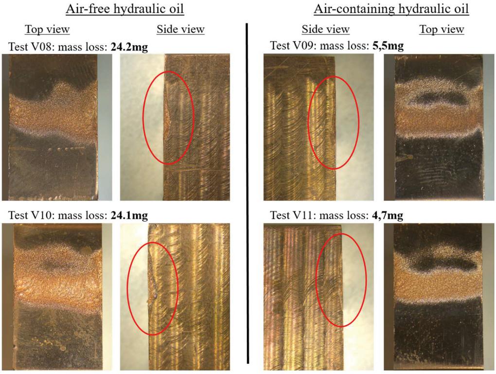
Figure 5 Copper samples eroded by cavitation (V08 and V10: air-free; V09 saturated; V11 oversaturated).
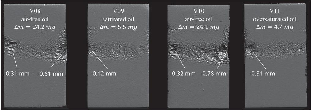
Figure 6 3D surface scans of the eroded copper samples.
Air-free mineral oil is significantly more erosive than normal, air-saturated oil at ambient reservoir-pressure of 1 bar absolute, but a further increase in the dissolved air content leads only to a slight additional decrease in cavitation erosion, compare V09 to V11. This small decrease could also be caused by the increased back pressure, but the increase in back pressure has almost no effect on the mass loss in the air-free experiments (compare V08 to V10). Although an increase in back pressure normally leads to a decrease in cavitation erosion, in this test the only slight increase in tank pressure is too small to significantly reduce erosion. The back pressure has a higher influence on erosion in the presence of free air, which corresponds to experience. However, air-free oil erodes seemingly independent of back pressure.
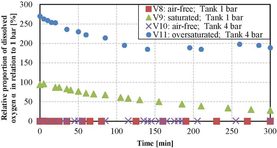
Figure 7 Proportion of dissolved air in the oil over the test duration.
Since in this paper the influence of (dissolved) air on cavitation erosion is investigated, it is important to monitor this parameter thoroughly. Figure 7 shows the temporal course of the dissolved oxygen concentration measured with the Clark electrode in the four experiments.
In the air-free experiments (V8 and V10), the concentration of dissolved oxygen is less than or equal to 1% during the whole experiment. This ensures that the oil is practically free of air. As there is no air, no pseudo nor gas cavitation can occur, only vapour cavitation.
In the air-containing experiments (V09 and V11) the amount of dissolved oxygen is not constant but decreases over time. This is because the desorption of air due to gas cavitation is greater than the slow absorption process. During the operation, more air is released than can be dissolved again. As a result, the amount of dissolved air decreases and the amount of free air increases until an equilibrium of absorption and desorption is reached. The free air bubbles can be seen in the bubble analysis section, as show in Figure 8. In addition, this double proves that there is actually no air in the air-free experiments.
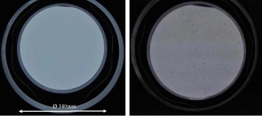
Figure 8 Photography through the bubble analysis sections: left: V08 – no bubble during the entire test duration; right V09 – Bubbles during the entire test duration.
4 Discussion, Conclusions and Implications
Since the experiments were carried out in a realistic flow geometry and under realistic operating conditions, the flow and cavitation fields correspond to those in real hydraulic valves. Therefore, the experiments have a very high transferability to reality.
In air-free experiments only vapour cavitation can occur, whereas in air containing experiments vapour, gas and pseudo cavitation will occur simultaneously.
The results show, that air-free mineral oil causes significantly more cavitation erosion damage than normal, air-saturated mineral oil. In fact, the obtained mass losses are 4.4–5.1 times higher, see Table 2. Because the results are highly unambiguous and reproducible, the experimental results are the expression of a general underlying physical principle.
The authors see the interpretation of the results as proof of the following theses:
1. Cavitation erosion on hydraulic components like valves and pumps is caused mostly by vapour cavitation.
2. Gas or pseudo cavitation does not cause any erosion on hydraulic components affected by hydrodynamic cavitation (e.g. jet caused cavitation).
3. The free air released by vapour- and gas cavitation dampens hydrodynamic cavitation (jet caused cavitation) erosion in hydraulic components significantly.
The observed damping effect through air can be explained by the strong increase in compressibility, which leads to a cushioning of the bubble collapse and attenuation of shock wave propagation. These results and interpretation for mineral oil are in alignment with numerous studies on cavitation erosion in other fluids, especially water.
To be clear, pseudo and gas cavitation can still cause major damage to the hydraulic system by damaging sealing, oil aging, reducing the stiffness of the system, etc. However, on the issue of hydrodynamic cavitation erosion pseudo and gas cavitation have an absolutely positive effect.
The results also suggest, that vapour cavitation in real hydraulic systems is not limited by a lack of cavitation nuclei. If cavitation erosion was limited by the number of nuclei, less mass loss would have to occur in the air-free experiments. The opposite is observed.
In this test rig, like in every practical application of a hydraulic system driven by typical mineral oil, it seems that despite the absence of free and dissolved air, there are still enough cavitation nuclei to induce strong vapour cavitation. The additional nuclei provided by the micro bubbles seem not to be needed for cavitation to occur. This is different to most experiments in water, where some amounts of dissolves air increase cavitation erosion. A possible explanation is, that the test stand is a real hydraulic system and not a sterile laboratory test. Even if a fine filter is used, there will always be micro- and nanoparticles in a real hydraulic system that function as nuclei. Another reason is that in contrast to water, mineral oil is not a pure substance with only one chemical compound of high purity but is a mixture of different base oils and additives. It is likely that some chemical compounds function as cavitation nuclei for other substances to evaporate. Further on, most of the additive-packages used for modification of the base-oils are a mixture of micro- and nanoscale particles within further chemical compounds. Some of these additives were already tested for their ageing-effects on hydraulic oils [10]. But in order to resolve this nuclei-issue on cavitation erosion, much more detailed work has to be done.
In general, hydraulic oil is much less erosive than water, for example. But as the experiments have shown, a large proportion of this positive property is due to the high content of dissolved air.
The fact that cavitation erosion in air-free mineral oil is much more aggressive, has implications on the design of future hydraulic systems.
In order to reduce the negative effects of gas and pseudo cavitation, a current development trend is to remove as much air as possible from the system by technical means, e.g. air separators, specials tanks, or by using liquids with a short air release time. Some applications such as electro-hydraulic compact drives even operate with air-free oil. This of course decreases all air-related problems, but largely increases cavitation erosion. If an application already has problems with cavitation erosion, it is not advisable to decrease the (dissolved) air content, as it would worsen the erosion damage.
An ongoing development trend towards higher power densities and thus higher pressure levels is also effected by cavitation erosion since the mass loss per time scales is over-proportionally related to the pressure drop, see Equation (1). Combined with the use of air-free oil, cavitation erosion in hydraulics will become a major challenge in the future. A brief summary of some possible methods to reduce cavitation erosion in hydraulic components is given in Table 3.
Table 3 Measures to reduce cavitation erosion
| Domain | Measure |
| Control and regulation |
• Avoidance of cavitation critical operating points • Avoidance of hydrolock • Back pressure |
| Design, structure and simulation |
• Cavitation optimized flow design • Multi-stage pressure drop |
| Material |
• Use of cavitation-resistant materials |
| Fluid |
• Use of weakly erosive fluids • Keeping “small” amounts of air in the liquid |
5 Summary
Cavitation erosion causes damage to hydraulic components like pumps and valves. Cavitation can be categorised into vapour, gas and pseudo cavitation each with different cause and effect. The literature does not agree whether cavitation erosion in hydraulic valves or pumps is caused by vapour and/or gas cavitation. Furthermore, there are no experiments in mineral oil known, which clearly separate the effects of the different cavitation types on the erosion.
To close this research gap, a special test rig with degassing capabilities has been designed, in which the air content can be adjusted and measured. As flow geometry a valve model with realistic dimensions and under realistic operating conditions is used. This guarantees very high transferability of the test results to real hydraulic valves.
Two 5 h long erosion test with air-free oil and two with air-containing oil are performed. The results show that air-free oil causes 4–5 times more mass lose than normal mineral oil. Based on the experimental results the authors conclude or all hydrodynamic (jet) caused cavitation that:
1. Cavitation erosion on hydraulic components like valves and pumps is caused by vapour cavitation – not gas or pseudo cavitation.
2. The air released by gas cavitation dampens cavitation erosion in hydraulic components significantly.
3. A large proportion of the weak cavitation erosivity of mineral oil is due to its high air content.
4. Measures to reduce (dissolved) air contained lead to a risk on cavitation erosion.
5. The absence of dissolved air seems not lead to a lack of cavitation nuclei in most real hydraulic systems.
6. Gas or pseudo cavitation does not cause any erosion on hydraulic components affected by hydrodynamic cavitation. Nevertheless, compression driven cavitation erosion can occur if free air bubbles are present in sufficient number and if operating conditions exceed pressure rise speeds of 100000 bar/s.
Cavitation erosion is and remains a fundamental challenge for the further development of hydraulic components, especially for increasing power density or the use of air-free oil.
Acknowledgement
The presented research activities are part of the project “Parametrierung von Kavitationsmodellen für die gezielte Betriebsbereichserweiterung ölhydraulischer Komponenten und Systeme”. The authors would like to thank the Fluid Power Research Fund of the VDMA for the funding and support.
The authors would also like to thank Morpheus Space Inc. for the 3D surface scans.
References
[1] S. Osterland und D. Herschel, “Druckflüssigkeiten für Hydraulikanlagen”, in Hydraulik – Fluid-Mechatronik, Berlin, Springer, 2020, p. 49.
[2] Gülich J.F, “Saugverhalten und Kavitation”, in Kreiselpumpen, Berlin, Springer, 2004.
[3] J. Fröhlich, F. Rüdiger und W. Heller, “Kompaktkurs Kavitation”, Dresden, 2015.
[4] P. Bathia, “Der Einfluss der geometrischen Form der Drosselspalte auf das Durchflußverhalten von Drosselventilen”, Dresden, Dissertation Technische Universität Dresden, 1963.
[5] U. Grätz, “Untersuchung zur Ableitung und zum Nachweis eines Kriteriums für Strömungskavitation in hydraulischen Achsen”, Forschungsfonds der Fachgemeinschaft Fluidtechnik im VDMA, Frankfurt a.M., 1994.
[6] D. Will, “Der Einfluss der Öltemperatur auf das Durchflußverhalten von Drosselventilen unter besonderer Berücksichtigung der Kavitation”, Dissertation Technnische Universität Dresden, Dresden, 1968.
[7] U. Iben, A. Morozov, E. Winklhofer und R. Skoda, “Optical investigations of cavitating flow phenomena in micro channels”, in WIMRC 3rd International Cavitation Forum, University of Warwick, UK, 2011.
[8] W. Kleinbreuer, “Untersuchung der Werkstoffzerstörung durch Kavitation in ölhydraulischen Systemen”, Dissertation, RWTH Aachen, Aachen, 1979.
[9] P. Lipphardt, “Untersuchung der Kompressionsvorgänge bei Luft-in-Öl-Dispersionen und deren Wirkung auf das Alterungsverhalten von Druckübertragungsmedien auf Mineralölbasis”, Dissertation RWTH Aachen, Aachen, 1975.
[10] P. Lipphardt, “Untersuchungen über das Lösen und Abscheiden dispergierter Luft in Druckmedien und ihre Wirkung in hydraulischen Kreisen”, Institut für hydraulische und pneumatische Antriebe und Steuerungen der RWTH Aachen, Aachen, 1976.
[11] J. Wu, K. Su and Y. Wang, “Effect of air bubble size on cavitation erosion reduction,” Sci. China Technol., pp. 523–528, 3, 2017.
[12] K. Kim und et al., “Advanced Experimental and Numerical Techniques for Cavitation Erosion Prediction”, Springer, Dordrecht, 2014.
[13] J. Auret und et al., “The influence of water air content on cavitation erosion in distilled water”, Tribology International, p. 431, 1993.
[14] A. Sotnikov und A. Livshits, “Effect of the Content of Free Air on Cavitation Erosion”, Hydrotechnical Construction, Vol. 28, No. 12, 1995.
[15] H. Lohrberg und B. Stoffel, “Training Seminar S2 Intelligent maintenance management of pumps – Avoiding cavitation erosion”, Karlsruhe, 2020.
[16] R. Böhm, “Erfassung und hydrodynamische Beeinflussung fortgeschrittener Kavitationszustände und ihrer erosiven Aggressivität”, Technische Univ. Darmstadt, Darmstadt, 1998.
[17] W. Heller, “Hydro-dynamic Effects with Particular Consideration of Water Quality and their Measurement Methods”, Saechsische Landesbibliothek – Staats – und Universitaetsbibliothek Dresden, Dresden, 2006.
[18] Lide und R. David, “CRC Handbook of Chemistry and Physics”, 85th ed., CRC Press, 2004.
[19] F. Rüdiger und S. Helduser, “Untersuchungen zur Schallabstrahlung ölhydraulischer Ventile”, Ölhydraulik und Pneumatik, OP Zeitschrift für Fluidtechnik, No. 4 and No. 5, 2004.
[20] L. Müller, F. Rüdiger, J. Weber, M. Schümichen, J. Fröhlich, T. Groß und P. Pelz, “Messverfahren und numerische Modellierung von Kavitation in einem ölhydraulischen Ventil”, Journal of “Ölhydraulik Pneumatik”, No. 2/2013, June 2013.
[21] L. Müller, F. Rüdiger, S. Helduser und J. Weber, “Visualisation of Cavitation in Oil Hydraulic Spool Valves”, in 8th International Conference on Fluid Power Transmission and Control (ICFP 2013), Zhejiang University, Hangzhou, China, 2013.
[22] A. Moosavi, S. Osterland, D. Krahl, L. Müller und J. Weber, “Numerical Prediction and Experimental Investigation of Cavitation Erosion of Hydraulic Components Using HFC”, in 12th International Fluid Power Conference (12. IFK), Dresden, 2020.
[23] Hydac Filter Systems GmbH, “Practical Contamination Management”, Sulzbach/Saar. 2009.
[24] W. Lauterborn und C.-D. Ohl, “Cavitation Bubble Dynamics”, in Ultrasonics Sonochemistry 4, 5th Meeting of the European Society of Sonochemistry, 1997.
[25] W. Backé, “Über Kavitationserscheinungen in Querschnittsverengungen von ölhydraulischen Systemen”, Industrieanzeiger, No. 63, 1962.
Biographies

Sven Osterland received his diploma in Diploma in Mechanical Engineering in the fields of structural durability from TU Dresden in 2014. Since 2014 he is working as Research Associate at the Chair of Fluid-Mechatronic Systems (Fluidtronics), Institute of Mechatronic Engineering, Technische Universität Dresden. His research areas include numerical multiphase flow simulations (CFD), experimental flow visualisation of cavitating hydraulic flows and cavitation erosion in hydraulic components.

Lutz Müller received his diploma in Aerospace Engineering from TU Dresden in 2002 and did his doctoral thesis on unsteady compressor aerodynamics in 2013. Since 2011 he is working as Research Associate at the Chair of Fluid-Mechatronic Systems (Fluidtronics), Institute of Mechatronic Engineering, Technische Universität Dresden. His research areas are mostly of experimental nature concerning many aspects of mechanics and hydromechanics of hydraulic components and systems.

Jürgen Weber has been appointed in 1st March 2010 as a University Professor and the Chair of Fluid-Mechatronic Systems as well as the Director of the Institute of Fluid Power at the Technische Universität Dresden, and took on the leadership of Institute of Mechatronic Engineering in 2018. He finished his doctorate in 1991 and was an active Senior Engineer at the former Chair of Hydraulics and Pneumatics until 1997. This was followed by a 13-year industrial phase. Besides his occupation as the Head of the Department Hydraulics and Design Manager for Mobile and Tracked Excavators, starting in 2002, he took on responsibility for the hydraulics in construction machinery at CNH Worldwide. From 2006 onwards, he was the Global Head of Architecture for hydraulic drive and control systems, system integration and advance development CNH construction machinery.
International Journal of Fluid Power, Vol. 22_3, 373–392.
doi: 10.13052/ijfp1439-9776.2234
© 2021 River Publishers