Analysis on the Steady-state Performance and Losses of a Bent-axis Type Hydraulic Motor Used in Heavy Earth Moving Machinery
Ajit Kumar Pandey*, Amit Kumar and Nitish Kumar
Department of Mechanical Engineering, National Institute of Technology, Patna, Bihar, India
E-mail: ajit.saurabh100@gmail.com; amit@nitp.ac.in; nitish.me15@nitp.ac.in
*Corresponding Author
Received 09 February 2021; Accepted 24 May 2021; Publication 03 July 2021
Abstract
Hydraulic components play a significant role in the mining and construction equipment. It is responsible for smooth change in the output speed, torque, and power of the machine. The hydrostatic drive powered by a constant speed electric motor is widely used in the propel system of the mining equipment. Regulation of the displacements of the pump and the hydro-motor of the drive facilitates the control of the straight running and steering of the machines.
In the present scenario, better efficiency and ease of control are the critical aspects to be considered in the design and selection of the hydraulic pump and motor used in underground mining operations. The bent axis hydro-motor is one such equipment that is an electro-hydraulic component that can work in an adverse working environment.
The present study deals with the performance analysis of fixed displacement bent axis hydro-motor at different operating parameters such as different temperatures, sizes, viscosity at different loads, and drive speed. For analysis, the hydraulic drive consists of a variable displacement pump rotated by a constant speed electric motor and a fixed displacement hydro-motor. The regulation of the pump displacement controls the speed of the drive. Manually controlled hydrostatic drive propels the said machine against variable load demands. The present work investigates the performances of the hydro-motor used in the mining and construction machine through detailed modeling and experimentations. The steady-state performances are analyzed in terms of slip, torque losses and efficiency of the hydro-motor. The study finds the design guideline to operate the hydrostatic drive using such motors in a reasonable efficiency zone.
The model is validated for various operating conditions of the equipment by comparing the predicted results with the test results. The outcome of the present work will be expedient for the preliminary design and assortment of similar hydraulic component used in the mobile, mining equipment.
Keywords: Bent axis hydro-motor, flow-loss, torque-loss, hydraulic oil temperature, overall efficiency.
1 Introduction
Bent axis hydro-motor has been extensively used in heavy earth moving machinery for high torque-speed range and overall efficiency. Such hydro-motor has a promising prospect in the application of the hydraulic system that requires simple and compact structure. While analyzing the hydro-motor performance, it is pertinent to consider its various losses. The losses of the pump and the hydro-motor have detrimental effects on the overall efficiency of the hydraulic drive. In recent decades, various approaches have been suggested by notable researchers to describe the losses of the hydraulic pumps and hydro-motors.
A good number of literatures are available in the area of fluid power components, covering different aspects like design, development, performance analysis, system identification, and efficiency. In this respect, some of the studies made in the recent past related to the present research work are discussed here.
Several literature available on the losses of the hydraulic drive consists of a variable displacement pump and fixed displacement motor [1, 2]. In implementing proportional control action to vary the swash plate angle of the pump, the studies have analyzed the system responses. By using the linear quadratic regulator, Saber et al. [3] has found that the performance of the pump controlled closed-loop hydraulic system was improved. They have linearised the system equations to get the predicted results. Sill et al. [4] have analyzed the dynamics of the vehicle as well as the lateral stability of its hydraulic drive. In their study, i.e the prime mover, internal combustion engine drives the variable displacement hydraulic pump to supplies power to the independently controlled four variable displacement hydraulic motors that drive the wheels of the vehicle. The system model integrates the vehicle dynamics with the steady-state models of the pump and the motor. However, the model presented in the work was not validated. Comellas et al. [5] have introduced an approach to study hydraulic drive systems and expressed as mathematical model of the complete driveline system for all-terrain vehicles. Huang et al. [6] have developed an asymmetric pump controlled system to obtain differential volume flow for the asymmetric cylinder which was not verified experimentally. Song et al. [7] have analyzed the swash plate adjustment mechanism of a variable displacement pump. The results of the simulation and experimental studies performed by them show that the controller based on the PI algorithm with feed-forward compensation achieves better dynamics compared to the conventional PI controller. Pedersen et al. [8] have proposed an event-driven digital controller for the speed control of a hydro-motor suitable for varying pressure and load torque conditions. The proposed controller shows better performance both with respect to the reference tracking and disturbance rejection. However, the performance of a digitally controlled machine used in the hydrostatic drive is limited, since the outputs are divided into discrete levels when utilizing at full displacement operation of the pump and the motor. Leaking valve-pump parallel control hydraulic system proposed by Ding et al. [9] shows improvement in the performance of dynamic response of the variable speed control pump with respect to its fast response. However, the test set-up shows that the said system has a greater but unstable damping ratio that reduces oscillations but increases the difficulty of parameter prediction. Nordas et al. [10] have made the simulation studies of the digitally controlled multi-piston machine providing variable flow to achieve higher efficiency compared to the conventional control. Such control provides the reduced magnitude and an output coupled power-split transmission systems. However, the said model does not consider the dynamics of the pump and the actuator. This paper presents a hydrostatic-mechanical power split transmission (PST) solution loader using the proposed PST solution can overall save about 8% energy [11]. Xiong et al. [12] have proposed a sizing procedure and modelling tool in designing efficient power train for a wheel loader. In this respect, they have compared the performances of directly coupled hydrostatic transmission in metal mi. The effects of the temperature and pressure on the leakage flow characteristic of the non-piston type positive displacement pumps have been investigated by Inaguma [13]. The investigation presented a practical approach to predict the influence of the operating pressure and the temperature on the leakage losses in different types of hydrostatic pumps. While establishing the leakage loss model, it also considers the variation of clearances with respect to the differential pressure. The results of the said analysis are limited to the non-piston type positive displacement pumps.
Different loss modeling methods for hydrostatic pumps and hydro-motors have been studied by Özfırat et al. [14] have analyzed the performance prediction of road headers, and discussed the art hydrostatic transform the flow and torque ripple when the pump operates near to full or zero displacements.
Bent axis hydro-motors, used in the hydrostatic system are suitable for the industrial applications; like Heavy Earth-Moving Machineries (HEMMs). The suitability of the hydro-motor at higher speed is due to its better control, high torque generation and higher power to weight ratio. In order to improve the performance of the hydrostatic drive using such hydro-motors, the detail analyses over the different performances are essential under different operating conditions. Further developments in this field for precise control of the actuators/hydro-motors, the use of electro-hydraulic system with computer aided electronic control has made the system more effective and attracted the researchers in the field of fluid power engineering. At the same time, improvement of the existing hydro-motors became necessary to cope-up with the present day needs. Analyzing the volumetric and hydro-mechanical efficiencies of the components, this paper examines the drive performance in terms of its overall efficiency, torque-loss and the slip for the reasonable operating range of the machine.
Such study may be useful for the designers to obtain the guidelines for the efficient operation of the hydrostatic drive under variable load demand.
The presents work investigates performance of five different sizes fixed displacement bent axis hydro-motor for wide torque-speed ranges and with variation in hydraulic oil temperatures. In evaluating the performance of the hydro-motors, the dependency of its various losses on hydraulic oil temperature, load torque, speed and the sizes of the hydro-motor are identified from the test results. Such studies have not yet been made. In this respect, a test set-up was fabricated and various losses of the hydro-motor for wide range of load torques and speeds at different hydraulic oil temperatures are analyzed. The explicit equations defining the losses and the performance of the hydro-motors should be useful in selecting the said drive for a given application.
2 The Physical System
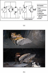
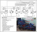
Figure 1 shows line diagram of the physical system for evaluating the performance of the hydro-motor.

Figure 1 (a) The physical system (b) SDL machine using similar hydro-motor working in an underground coal mine.
A swash plate controlled variable displacement pump (1) supplies flow to drive the hydro-motor (3) at different speeds. In turn, the hydro-motor drives the inertia load (6) and the loading pump (4), the flow supplied by which passes through the proportional pressure relief valve (5) that provides resistive load on the hydro-motor. By adjusting the displacement of the pump (4) and the set pressure of the proportional pressure relief valve (PPRV) (5), the performance of the hydro-motor was tested at different load torque (T) levels. The pressure relief valve (2) is used to control or limit the pressure in the system. The tests were conducted for five different capacities of the hydro-motor (D) ranging from 10cc/rev through 28cc/rev and the temperature of the hydraulic oil (T) was varied from 52C to 72C. Precautions were taken to keep the hydraulic oil temperature and load torque constant during measurements. The detailed experimental set-up is discussed in Section 4.
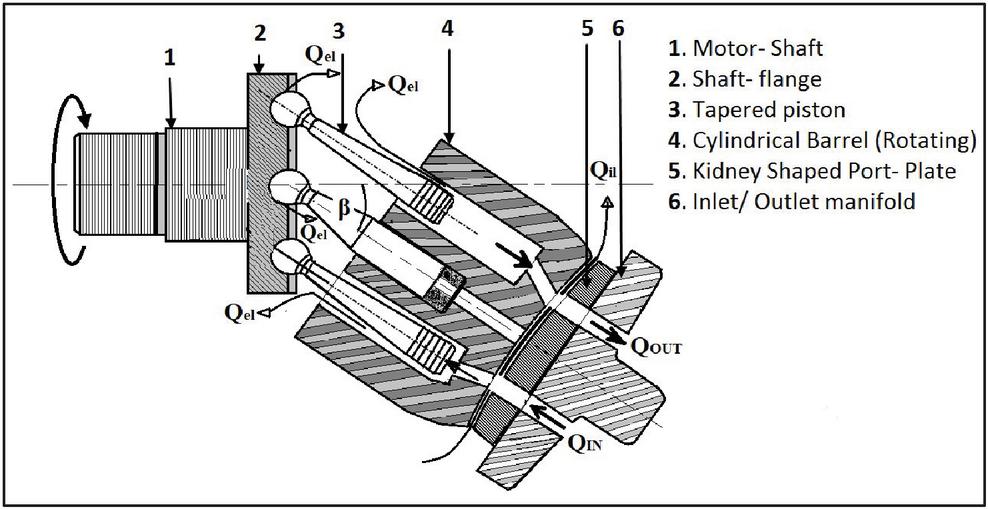
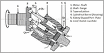
Figure 2 Fixed displacement bent axis hydro-motor.
Figure 2 shows the fixed displacement bent axis hydro-motor considered for the present study. In this hydro-motor, the inlet port is at a higher pressure compared to the outlet port that results in inter-port leakage, known as internal leakage (Q) of the hydro-motor. Apart from this, the leakage flow arises due to the pressure difference between the pumping chambers and the case drain, such leakages are known as external leakage (Q) of the hydro-motor.
3 Modelling of the System
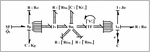
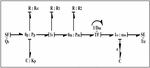
The Bond graph simulation technique [15] is an effective tool for modelling and simulation of any physical system that consists of multi domain. Using such technique the describing equations of the system are easily derived from the model. Figure 3 represents the multi bond graph model of overall physical system that consists of morphologically similar sub system. The motor’s chambers experience similar compression and expansion stages sequentially. Figure 4 indicates equivalent steady-state model of a bent axis hydro motor.
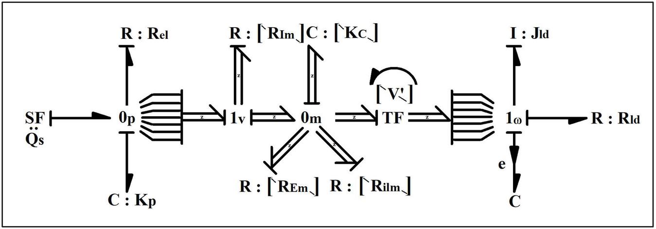
Figure 3 Multi bond graph model of a bent axis hydro-motor.
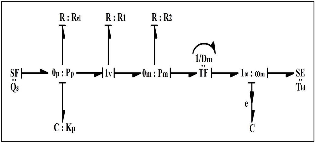
Figure 4 Equivalent steady-state model of a bent axis hydro-motor.
The steady-state equations derived from the model are as follows:
The predicted speed of the hydro-motor
| (1) |
Ignoring the flow loss due to fluid compressibility (Q) at motor inlet in steady state, the flow through the inlet port of the hydro-motor is given as:
| (2) | |
| (3) |
From Equation (1)
| (4) |
where,
| (5) |
The predicted performance parameters of the hydro-motor are determined as follows:
The predicted load torque (T) of the motor may also be written as:
| (6) |
where, the torque loss due to valve port resistance is given by:
| (7) |
Supply flow to the motor chamber through the valve port is given by:
Therefore the Pressure drop due to valve port resistance R
Equivalent predicted torque-loss is given by:
Therefore the predicted load torque expressed as
The predicted efficiency of the motor is expressed as follows:
| (8) |
As mentioned earlier, slip of the hydro-motor is due to its flow loss through the various leakage paths, considered as resistance R and R in the model.
Considering the external and the internal leakage flow of the hydro-motor, the total leakage flow is given by:
| (9) |
Therefore the predicted slip of hydro-motor with respect to its supplied flow rate Q is given by:
| (10) |
The actual performance parameters of the hydro-motor are given by:
| (11) | |
| (12) |
where,
| (13) | |
| (14) |
where,
| (15) |
4 Experimental Test Set-up
Commercially available fixed displacement bent axis hydro-motor of five different capacities with seven chambers in each hydro-motor is used in the experiment. The , S (%), and the overall performance of the five hydro-motor at the three different hydraulic oil temperature levels have been carried out experimentally using the test set-up shown in Figure 5. The performance of the hydro-motor were determined at different torque levels while the speed varies from 700 rpm to 1500 rpm.
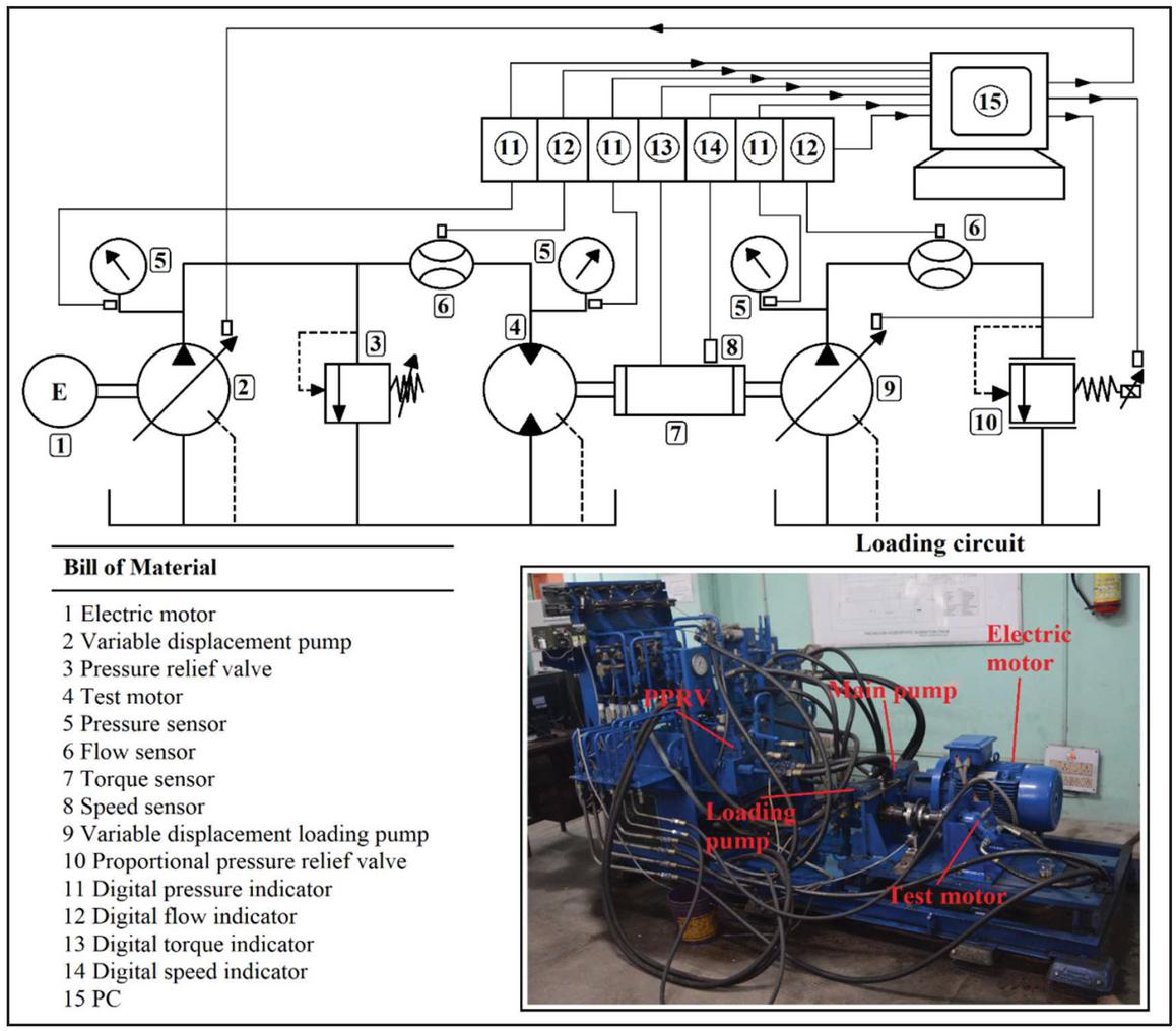
Figure 5 Experimental set-up.
A variable flow pump (2) rotating at a constant speed supplied pressurised fluid to the test motor (4). The test motor in turn drive the loading circuit that comprised of a pump (9) and a relief valve (10). Changing the flow of the loading pump by varying its swash plate angle or by adjusting the set pressure of the relief valve (10), the hydro-motors were tested at different load torques and speeds. The adjustments of the swash plate angle of the pump and the set pressure of the valve were made through control signal that changed from 0 to 10 V dc.The sensors along with the digital indicators recorded the pressure (P), flow (Q), rotational speed (), hydraulic oil Temperature (T) and load torque (T) on the hydro-motor.The tests were performed for a range of hydraulic oil temperature (T), load torque (T) and the hydro-motor speed () that vary from 52C to 72C, 10 N m to 25 N m and 700 to 1500 rpm, respectively. A thermal regulation system provided in the experimental test set-up to warming up and maintenance of working liquid temperature in a hydraulic system within the range of C and reduces achievement time of the recommended oil temperature level to minutes of thermal regulation system continuous work at various reference temperatures of air.
Table 1 List of major component used in the test-rig
| Name and Specification | Model/Make |
| 3-Phase induction motor Power: 15 KW Speed: 1450 RPM | NADJ40224HTOP Compton Greaves Ltd. |
| Variable displacement main pump Maximum displacement (D): 28 cc/rev | A4VG28EP2DM1/3XRPZC10F02D/Bosch Rexroth, Germany |
| Fixed displacement hydro-motor Displacement (D): 10 cc/rev Fixed displacement hydro-motor Displacement (D): 12 cc/rev Fixed displacement hydro-motor Displacement (D): 16 cc/rev Fixed displacement hydro-motor Displacement (D): 23 cc/rev Fixed displacement hydro-motor Displacement (D): 28 cc/rev | A2FM10/61W-VBB030, Bosch Rexroth, Germany A2FM12/61W-VBB040, Bosch Rexroth, Germany A2FM10/61W-VBB030, Bosch Rexroth, Germany A2FM23/61W-VBB030, Bosch Rexroth, Germany A2FM28/61W-VBB020, Bosch Rexroth, Germany |
| Variable displacement loading pump Maximum displacement (D): 28 cc/rev | A4VG28EP2DM1/3X–RPZC10F02D/Bosch Rexroth, Germany |
| Pressure sensor Accuracy: 0.25 % Pressure range: 0–200 bar | S10/Wika, Germany |
| Flow sensor Turbine type flow sensor Accuracy: 0.5% Flow range: 0–60 LPM | TFM 1015/Rockwin Flow meter India Pvt. Ltd |
| Torque sensor Accuracy: 1% of full scale torque Max. torque range: 100 Nm | K-T40B-100Q-MF-S-M-DU2-0-S/ HBM, Germany |
Characteristics of the instrumentation used in the measurements (pressure measurement, torque measurement, flow rate measurement, hydraulic motor rotation speed measurement) are provided in Appendix 2.
5 Results and Discussions
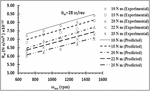
In evaluating the performance of the hydro-motors, its torque and the flow losses were identified that varied with the T, , T and the sizes of the hydro-motors (D). Using them the test data of , P, Q and T in Equations (2) to (4) for five different sizes of the hydro-motors (10 cc/rev through 28 cc/rev), the values of R, R and R were obtained at three different temperatures. The characteristics of these loss co-efficients were obtained from best fit curves lines to the data points at different T. Using them, the effects of variation of hydraulic oil temperature on the performance of different capacities of hydro-motor were studied.
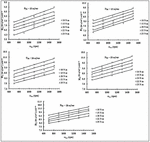
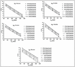
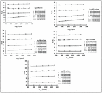
5.1 Determination of the External Leakage Resistance (R) of Hydro-motors (10cc/rev Through 28 cc/rev) at Three Different Temperature Levels (T)
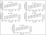
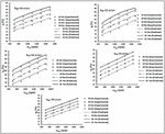
Figures 6 to 8 show the characteristics of R for five different capacities hydro-motor (10 cc/rev through 28 cc/rev) at three different temperature (T) (52C through 72C). These are plotted with respect to hydro-motor speed () at different load torque (T).
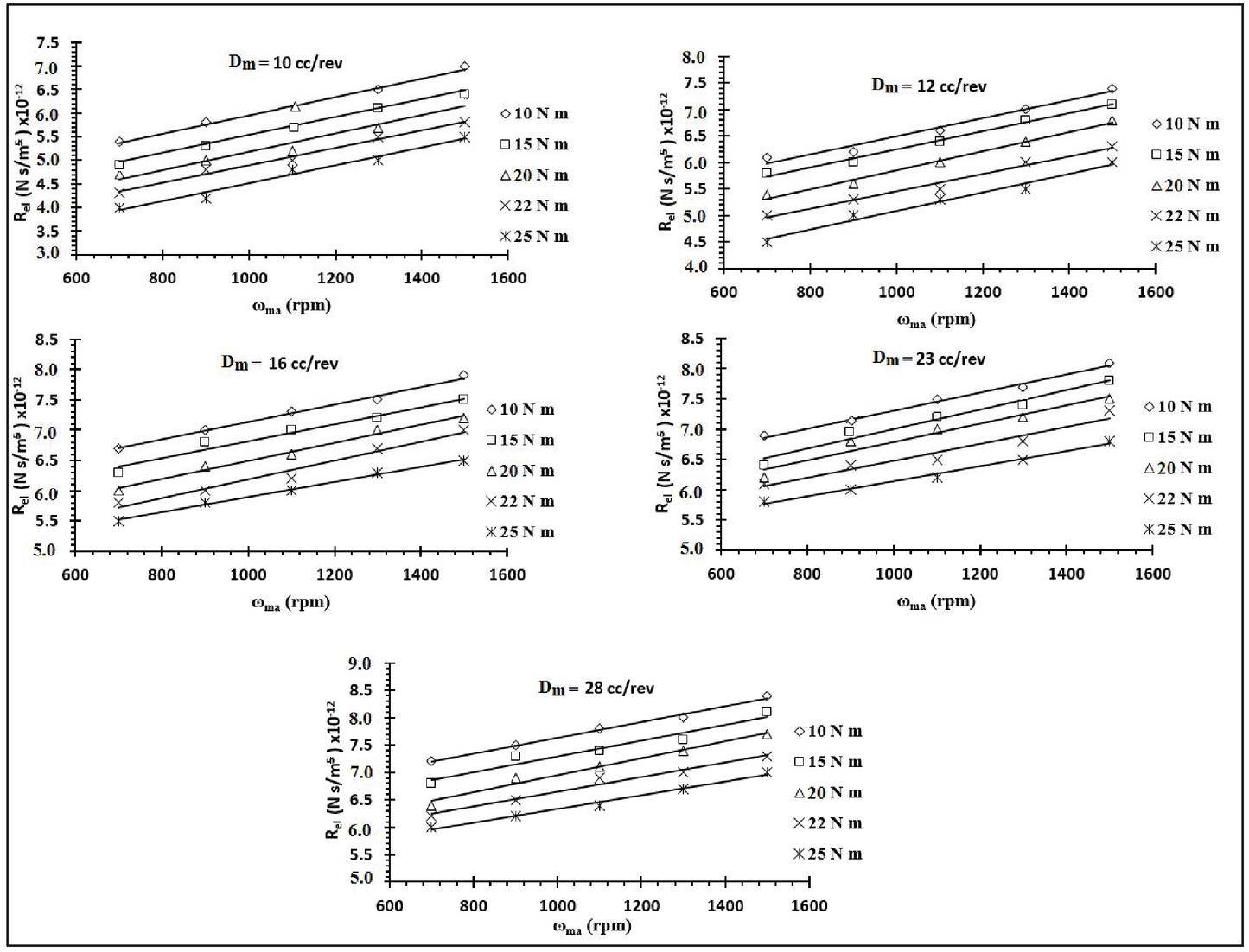
Figure 6 External leakage resistance (R) characteristic of bent axis hydro-motor of 10 cc/rev through 28 cc/rev at 52C.
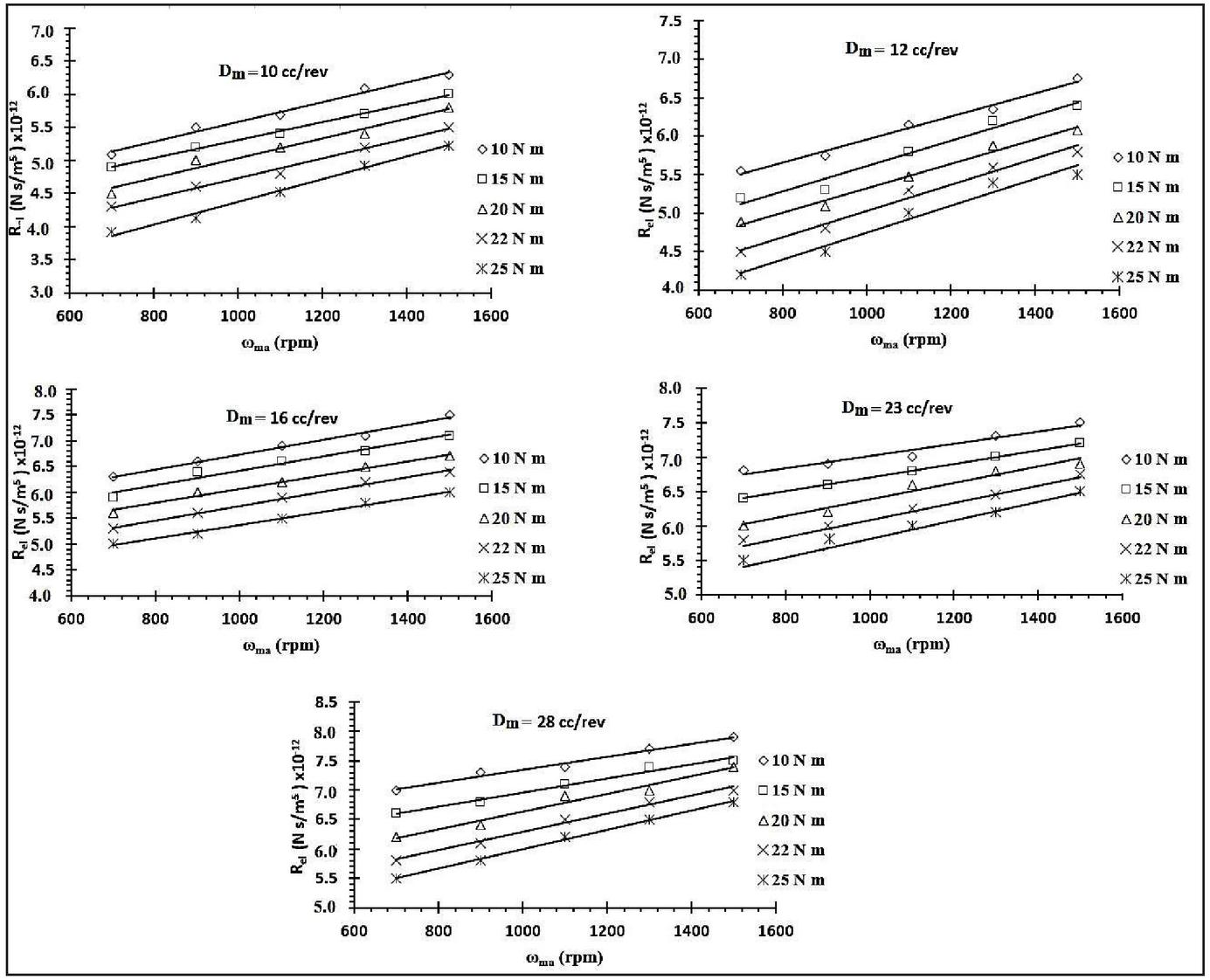
Figure 7 External leakage resistance (R) characteristic of bent axis hydro-motor of 10 cc/rev through 28 cc/rev at 65C.
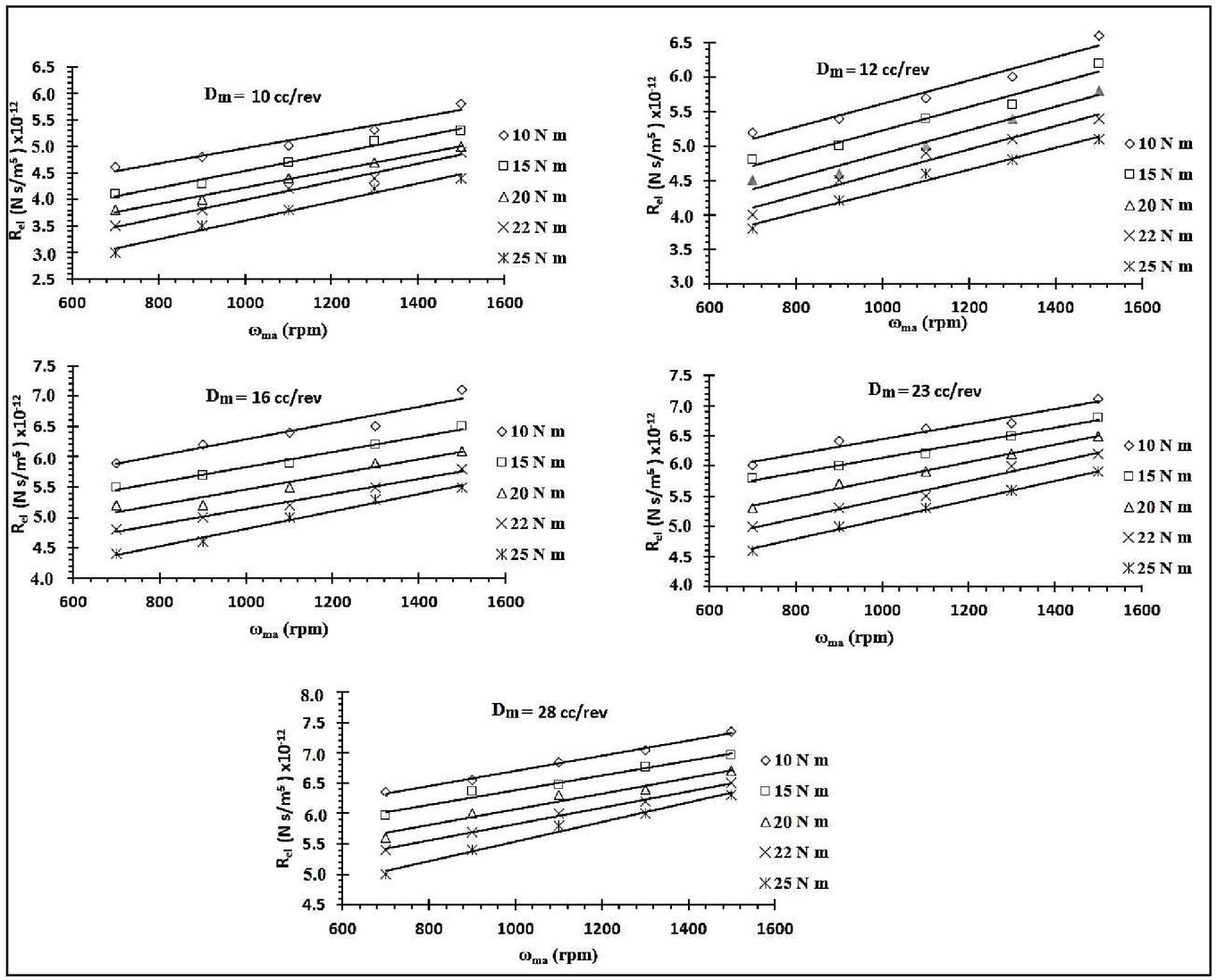
Figure 8 External leakage resistance (R) characteristic of bent axis hydro-motor of (10 cc/rev through 28 cc/rev) at 72C.
From Figures 6 to 8, the following conclusions are made:
• At a given T, with the increase in the hydro-motor speed (), the external leakage resistance (R) increases. It is due to the fact that increasing speed results in the decreasing flow losses.
• For a particular hydro-motor speed (), with the increase in the load torque (T), the external leakage resistance (R) decreases. With the increase in the load torque, the pressure across the motor also rises and leads to increase in the pressure-induced leakage flow through the clearance of the motor and hence the leakage flow rises and external leakage resistance decreases.
• At a constant oil temperature (T), the external leakage resistance (R) rises with rise in the capacities of (D). This is because of the leakage flow through clearance decreases with increase in stroke length of the piston.
• As the oil temperature (T) increases for a constant size of the hydro-motor (D), the external leakage resistance (R) decreases. This occurs mainly due to decreases in the oil viscosity with increasing oil temperature.
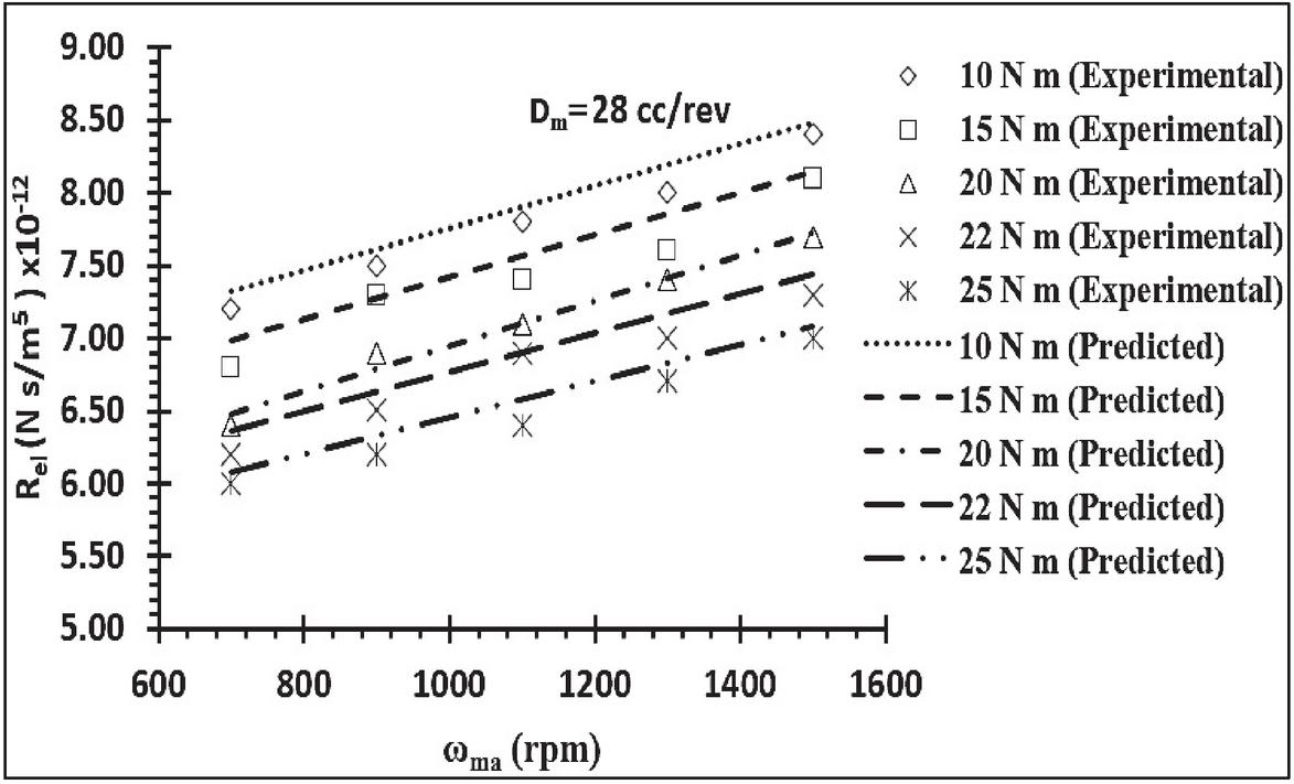
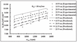
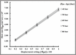
Figure 9 Comparison of predicted and experimental external leakage resistance (R) characteristic of bent axis hydro-motor of 28 cc/rev at 52C.
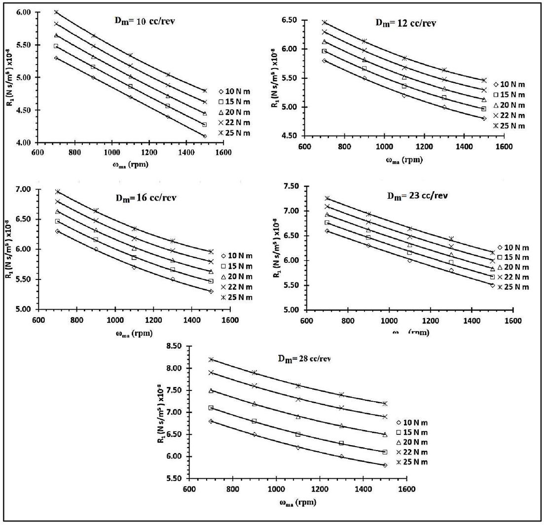
Figure 10 Inlet valve-port resistance (R) characteristic of bent axis hydro-motor(10 cc/rev through 28 cc/rev) at 52C.
The following procedure was adopted to do the uncertainty analysis for recorded data through experimental.
• Draw the “best” line through all the points, taking into account the error bars. Measure the slope of this line.
• Draw the “min” line – the one with as small a slope as you think reasonable (taking into account error bars), while still doing a fair job of representing all the data. Measure the slope of this line.
• Draw the “max” line – the one with as large a slope as you think reasonable (taking into account error bars), while still doing a fair job of representing all the data. Measure the slope of this line.
• Calculate the uncertainty in the slope as one-half of the difference between max and min slopes.
The comparison of the experimental and predicted data of the R is shown in Figure 9. It is observed that the predicted and the experimental data are in close agreement (deviation of 2% to 2.5%).
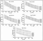
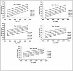
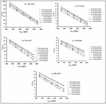
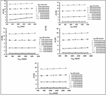
5.2 Determination of the Inlet Valve Port Resistance (R) of Hydro-motors (10cc/rev Through 28 cc/rev) at Three Different Temperature Levels (T)
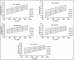
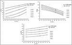
Figures 10 to 12 show the nature of R of five different capacities hydro-motor (10 cc/rev through 28 cc/rev) at three different temperature (T) (52C to 72C). These are plotted with respect to hydro-motor speed () at different load torque (T).
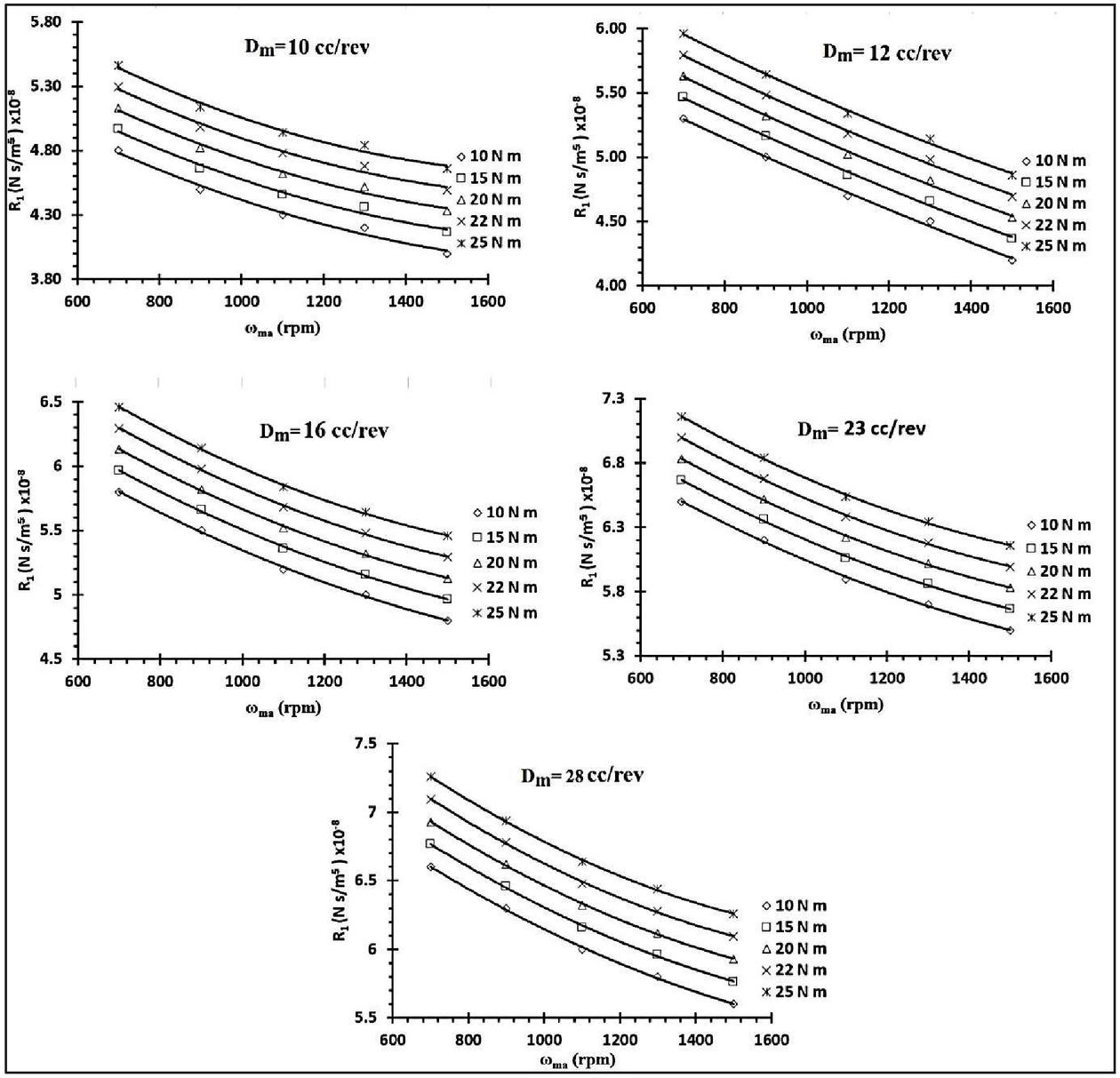
Figure 11 Inlet valve-port resistance (R) characteristic of bent axis hydro-motor (10 cc/rev through 28 cc/rev) at 65C.
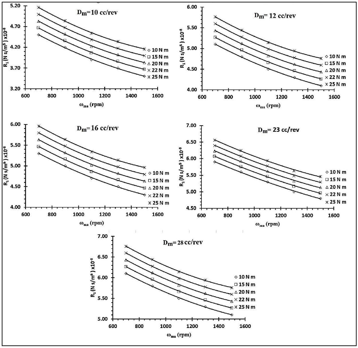
Figure 12 Inlet valve-port resistance (R) characteristic of bent axis hydro-motor of 10 cc/rev through 28 cc/rev at 72C.
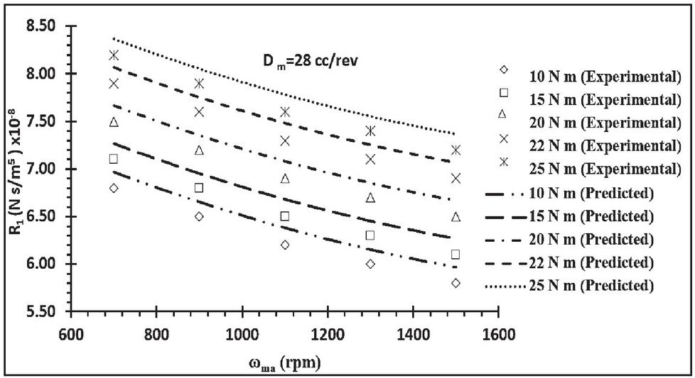
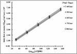
Figure 13 Comparison of predicted and experimental inlet valve port resistance (R) characteristic of bent axis hydro-motor of 28 cc/rev at 52C.
From the nature of curve shown in Figures 10 to 12, the conclusions made are as follows:
• For a constant T, with the increase in the , the R decreases. This is due to reason that with increasing speed, the flow supplied at the inlet valve increases and valve port resistance decreases as given by Equation (3).
• With the rising load torque (T) and for a particular , the inlet valve-port resistance (R) increases. This is due to increase in pressure drop the inlet valve port of the hydro-motor.
• At a constant oil temperature (T), inlet valve-port resistance (R) increases with increasing in the capacities of the hydro-motor (D). This may be attributed to the reason that with the increase in the size hydro-motor the losses due to increasing inertia of the motor increases.
• As the oil temperature (T) increases for a given size of the hydro-motor (D), inlet valve-port resistance (R) decrease. This is due to the effect of oil viscosity which reduces with rising temperature leads to reduce the viscous resistance and hence lower the valve port resistance.
The comparison of the experimental and predicted valve of the R is shown in Figure 13. It is observed that the predicted and the experimental data is in close agreement (deviation of 2% to 2.5%).
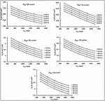
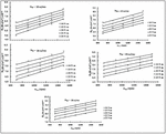
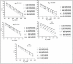
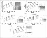
5.3 Determination of the Internal Leakage Resistance (R) of Hydro-motors (10cc/rev Through 28 cc/rev) at Three Different Temperature Levels (T)
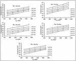
Figures 14 to 16 show the characteristics of R for five different capacities hydro-motor (D) (10 cc/rev through 28 cc/rev) at three different temperature (52C through 72C). They are plotted with respect to the hydro-motor speed () at different load torque (T).
Figure 14 Internal leakage resistance (R) characteristic of bent axis hydro-motor of 10 cc/rev through 28 cc/rev at 52C.
Figure 15 Internal leakage resistance (R) characteristic of bent axis hydro-motor of 10 cc/rev through 28 cc/rev at 65C.
Figure 16 Internal leakage resistance (R) characteristic of bent axis hydro-motor of 10 cc/rev through 28 cc/rev at 72C.
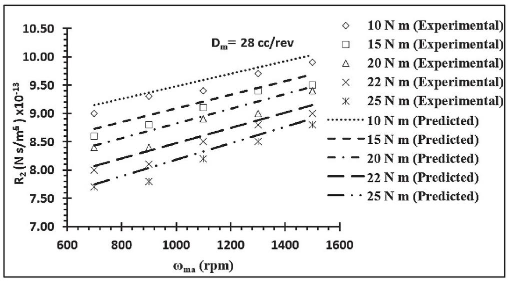
Figure 17 A comparison of predicted and experimental internal leakage resistance (R).
The following conclusion are made drawn the nature of curve shown in Figures 14 to 16.
• At a given T, with the increase in the hydro-motor speed (), the internal leakage resistance (R) increases, which is due to the reason that with increasing speed leakage flow decreases?
• With the rising load torque (T) and for a particular hydro-motor speed (), the internal leakage resistance (R) decreases, which is due to the increase in the pressure-induced leakage flow through the clearance of the motor with rising load torque and hence the leakage flow rises and leakage resistance decreases.
At a constant oil temperature (T), the internal leakage resistance (R) rises with increase in the capacities of the hydro-motor (D). This is because of the leakage flow through clearance decreases with increase in stroke length of the piston.
• As the oil temperature (T) increases for a constant size of the hydro-motor (D), the R decreases. This occurs mainly due to decreases in the oil viscosity with increasing oil temperature.
• The decrease in the resistances R and R of the hydro-motor increases the flow loss (slip) resulting in the decrease in the volumetric efficiency of the hydro-motor, whereas, the torque loss of the hydro-motor increases with the increase in the inlet valve-port resistance (R) which results in lowering the hydro-mechanical efficiency.
The comparison of the experimental and predicted values of the R is shown in Figure 17. It is observed that the predicted and the experimental data are in close agreement (deviation of 2% to 2.5%).
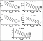
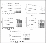
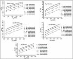
5.4 Determination of the Slip (in percentage) Characteristics of Hydro-motors (10cc/rev Through 28 cc/rev) at Three Different Temperature Levels (T)
Using the characteristics of the resistances (R and R) in Equation (10), the predicted slip of the five different sizes hydro-motor at three different oil temperature is obtained. The predicted slip and the actual slip are compared and are shown in Figures 18 to 20.
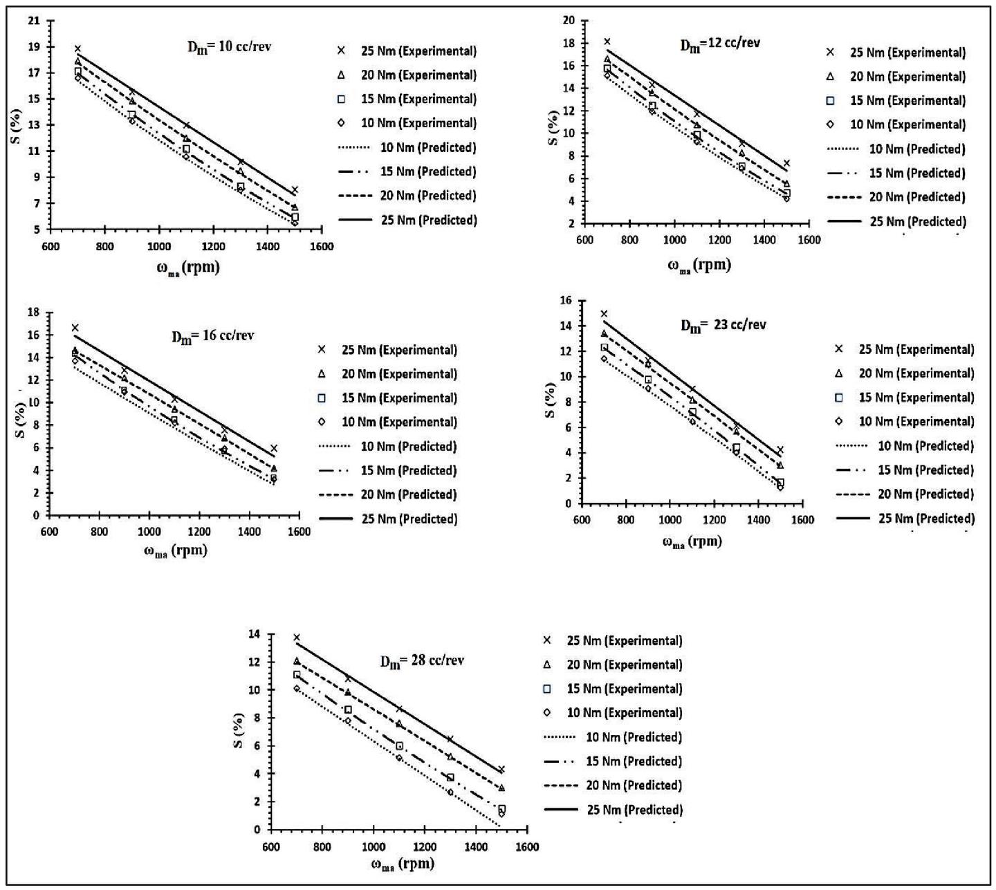
Figure 18 Slip characteristic of bent axis hydro-motor of 10 cc/rev through 28 cc/rev at 52C.
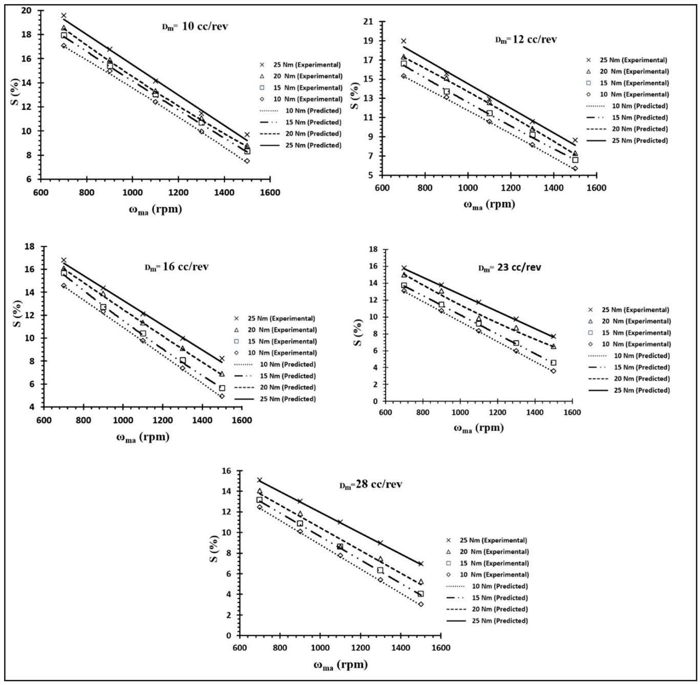
Figure 19 Slip characteristic of bent axis hydro-motor of 10 cc/rev through 28 cc/rev at 65C.
Figure 20 Slip characteristic of bent axis hydro-motor of 10 cc/rev through 28 cc/rev at 72C.
The conclusions drawn from Figures 17 through 20 are as follows
• At a constant T, with the increase in the hydro-motor speed (), the slip of the hydro-motor decreases. This is due to the fact that the external leakage resistance (R) and the internal leakage resistance (R) increase.
• At a constant hydro-motor’s speed (), the hydro-motor’s slip increases with the increasing in T. This is due to the fact that the external leakage resistance (R) and R decreases.
• As the size of the hydro-motor increases, the slip of the hydro-motor decreases at a constant oil temperature (T). This means that external leakage resistance (R) and the internal leakage resistance (R) increases
• For a given D, the slip of the hydro-motor increases with the increasing oil temperature (T). This indicates that the external leakage resistance (R) and the internal leakage resistance (R) decreases
5.5 Determination of the Torque-loss (%) Characteristics of Hydro-motors (10 cc/rev Through 28 cc/rev) at Three Different Temperature Levels (T)
Torque loss of the hydro-motor depends on the R. Using the characteristics of R) in Equation (7), the predicted torque loss of the five different sizes of hydro-motor at three different temperatures is obtained. The predicted and the actual torque loss are compared as shown in Figures 21 through 23.
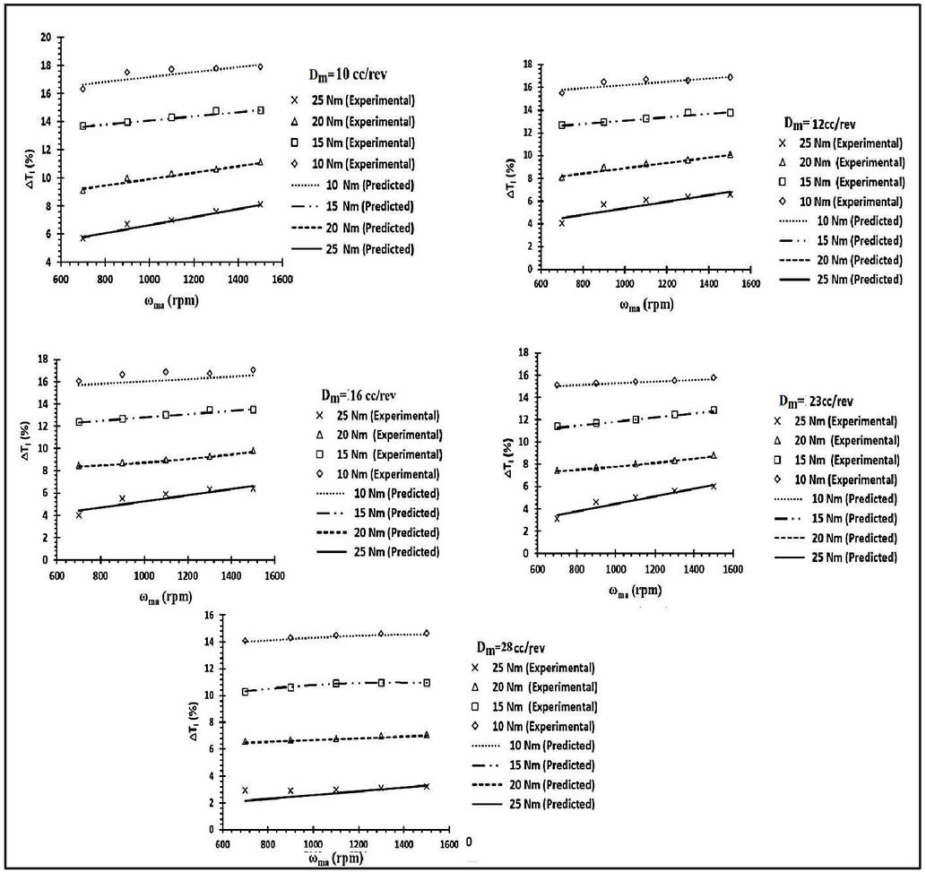
Figure 21 Torque loss characteristic of bent axis hydro-motor of 10 cc/rev through 28 cc/rev at 52C.
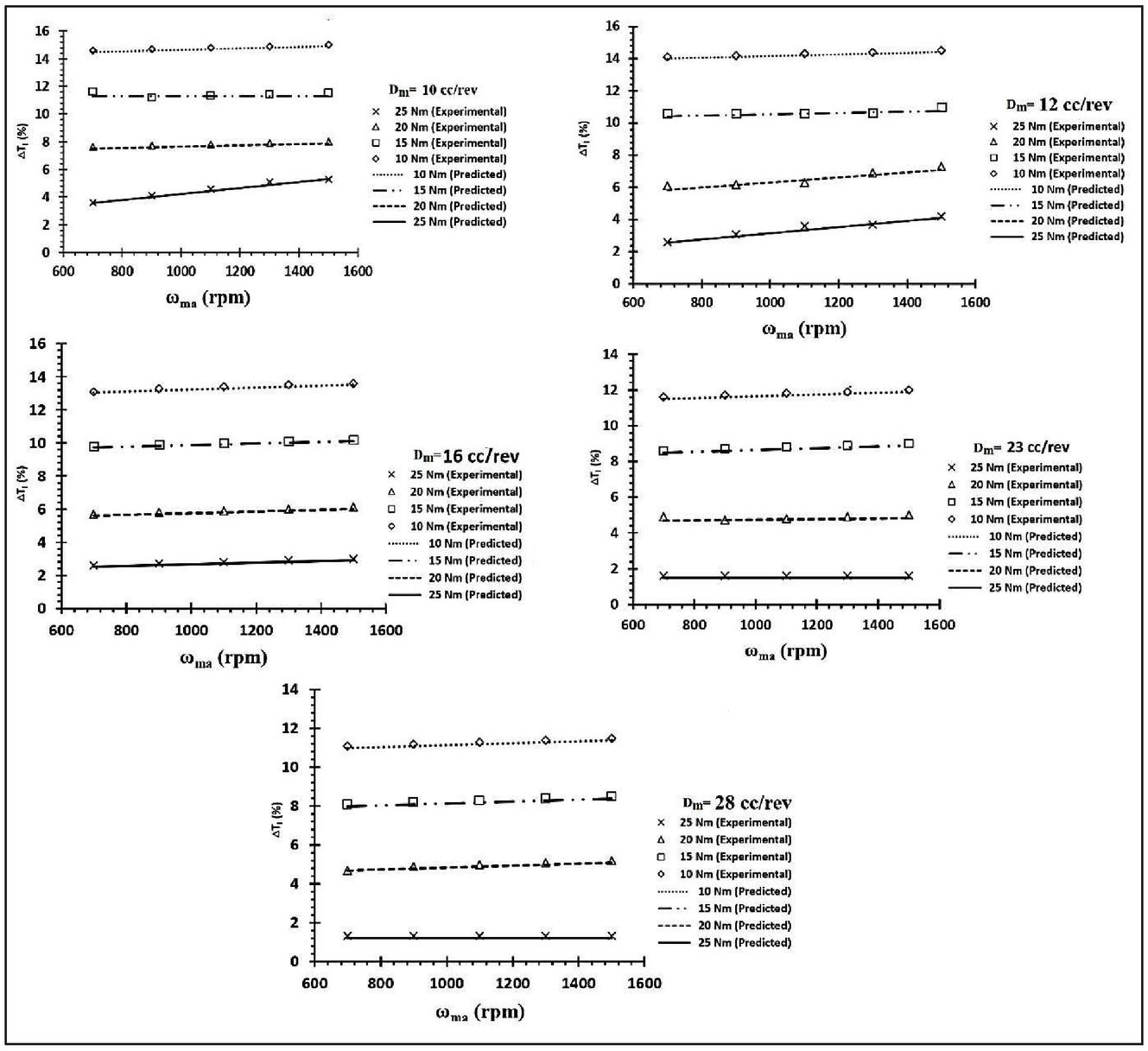
Figure 22 Torque loss characteristic of bent axis hydro-motor of 10 cc/rev through 28 cc/rev at 65C.
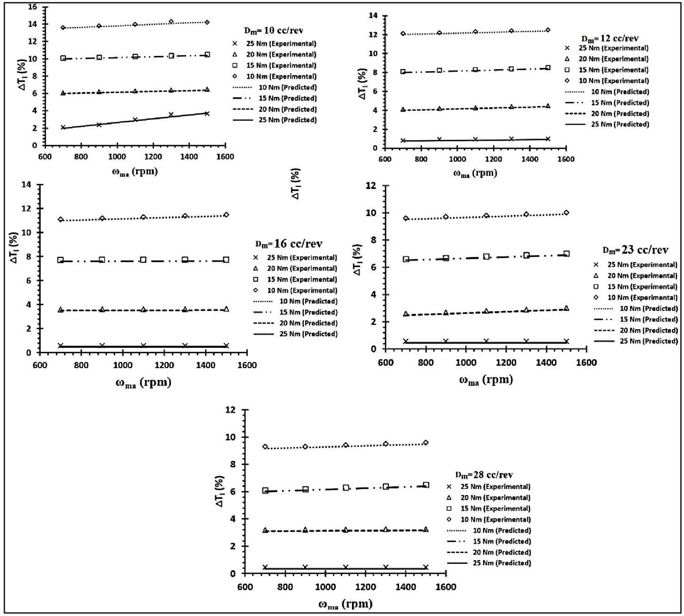
Figure 23 Torque loss characteristic of bent axis hydro-motor of 10 cc/rev through 28 cc/rev at 72C.
From the characteristics shown in Figures 21 to 23, the following observations are made:
• With increase in the hydro-motor speed (), the percentage of torque loss of the hydro-motors increases for a constant load torque (T). This is due to the increase in the viscous friction with increasing speed.
• At a given hydro-motor speed (), with the increase in T, torque loss percentage of the hydro-motors decreases. This is mainly due to the reason that R increases with increasing T at a constant speed hence torque loss increases and torque loss (%) decreases.
• As the size of the hydro-motor increases (D), the torque loss percentage of the hydro-motor decreases for a given oil temperature (T). This is because the inlet valve-port resistance (R) increases with increasing size; hence torque loss increases and torque loss percentage decreases.
• For a specific size of the hydro-motor (D), with the increases in the oil temperature (T), the percentage of torque loss of the hydro-motors decreases. This is due to decreases in the viscosity of oil with increasing temperature.
5.6 Determination of the Overall Efficiency of Hydro-motors (10 cc/rev Through 28 cc/rev) at Three Different Temperature Levels (T)
The overall efficiency of the hydro-motor depends on the slip and the percentage of torque loss. Slip and the percentage of torque loss depend on the various losses (R, R and R) of the hydro-motor. Using the characteristics of such losses in Equation (8), the predicted overall efficiency of the five different sizes hydro-motor at three different oil temperatures have been obtained. They are compared with the actual efficiency obtained through test data using Equation (10) and are shown in Figures 24 through 26.
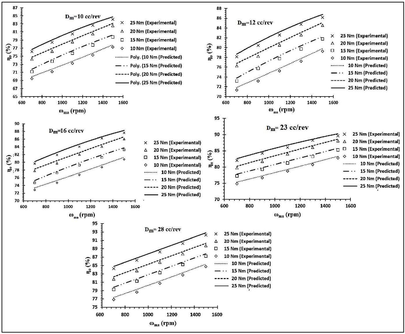
Figure 24 Overall efficiency of bent axis hydro-motor of 10 cc/rev through 28 cc/rev at 52C.
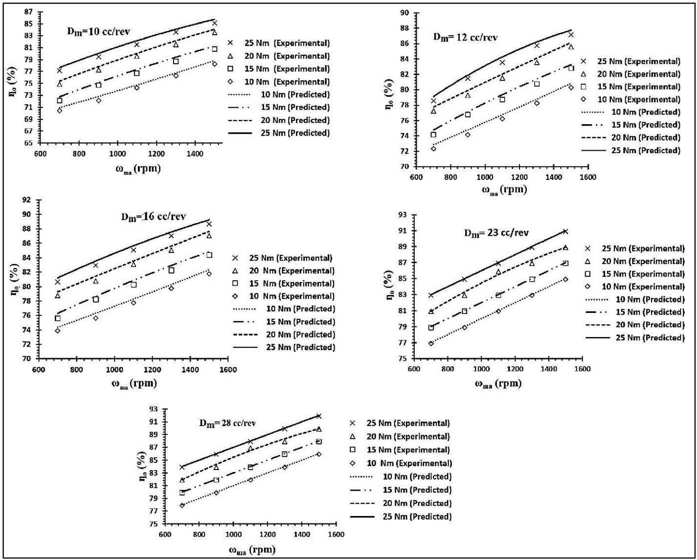
Figure 25 Overall efficiency of bent axis hydro-motor of 10 cc/rev through 28 cc/rev at 65C.
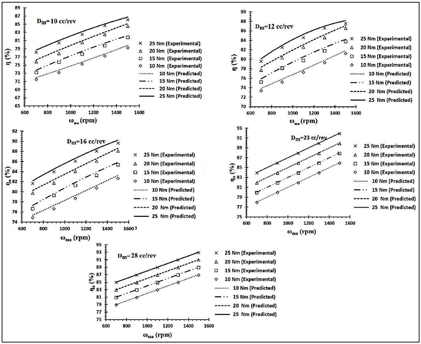
Figure 26 Overall efficiency of bent axis hydro-motor of 10 cc/rev through 28 cc/rev at 72C.
The following conclusions are drawn from the characteristics illustrated in Figures 21 through 23.
• At a constant T, with increasing , the overall efficiency increases. This is due to the decreasing nature of the slip.
• The overall efficiency of the hydro-motor rises with the increasing T at constant motor’s speed (), which is mainly due to the decreasing nature of the percentage of torque loss.
• At a given oil temperature (T), with the increase in D, the overall efficiency also increases. This is because the decreasing nature of the slip and the percentage of torque loss.
• For a fixed size of the hydro-motor (D), the overall efficiency increases with the increasing oil temperature (T). This is due to the decreasing nature of the percentage of torque loss.
It is observed that the predicted slip is lower by 1.5% to 2.5% in comparison to the test data and efficiency calculated from the equation obtained from the model is slightly higher than experimental data by 1% to 2%.
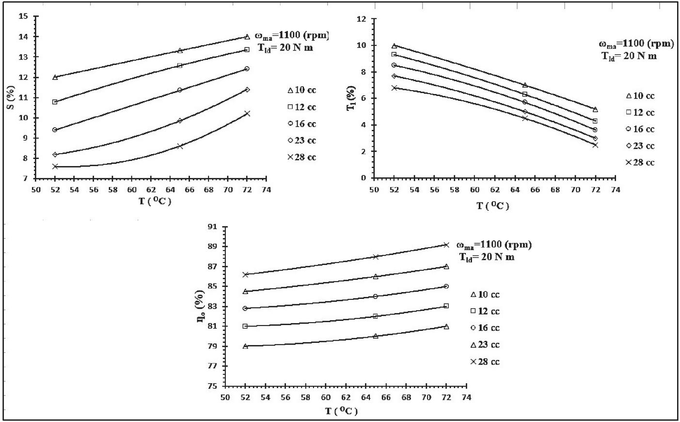
Figure 27 Slip (%), torque loss (%) and overall efficiency performance of different sizes (D) of the hydro-motor with respect to oil temperature (T).
5.7 Comparison of the Slip (%), Torque Loss (%) and Overall Efficiency of the Hydro-motors at Three Different Temperature Level (T) for a Constant Speed and Load Torque (T)
From the characteristics shown in Figure 27, the following observations are made:
• For a constant motor speed () and load torque (T), with increase in the oil temperature (T), the slip decreases with increase in the hydro-motor capacities. e.g. 28 cc/rev show lower slip (%) as compared to smaller size motor (e.g. 10 cc/rev through 23 cc/rev).
• With increase in the oil temperature, torque-loss percentage reduces with increase in size of the hydro-motor for a constant load and hydro-motor speed.
The hydrostatic drive of an SDL machine is subjected to a wide range of torque and speed variations during loading and unloading operations of the equipment. As the oil temperature rises, the overall efficiency increases with increase in the hydro-motor capacities. This is due to the fact that the slip and the torque-losses are more for small size motors as compared to large size motor for same load and speed.
The system considered for the analysis has wide applications in heavy earthmoving machinery, where the torque-speed characteristic of the machine is one of critical parameters. Therefore, the proposed model will also be useful for the design considerations of the hydraulic drives used in mining equipment. The detailed frequency analysis may give more insight of the systems, which may be taken up in the course of future work. It may also be noted that the conclusion is acquired under the conditions of constant pump speed. Future work will include considering the variable pump speed and designing a suitable controller to achieve the system’s desired performance.
There are several factors that are not considered in the modelling and analysis which results into the overestimation of the hydro-motor performance. They are the bearing friction, compressibility flow loss, additional minor leakage and pressure loss of the motor due to elastic deformation of the piston assemblies, hydro-dynamic losses and instrumental error as well. Consideration of these needs more detailed analysis and rigorous experiments.
6 Conclusions
A steady-state model using bond graph simulation technique has been developed for a multi piston bent axis hydro-motor. Using the derived equation for the model, the performance of five different sizes of the motor at different temperature has been verified experimentally. The nature of them has been established through test data which have found to have non-linear relationship with T, , D which also vary with temperature (T).
The small differences between the predicted and the test responses are due to the line losses, losses through the additional leakage paths, instrumental errors as well. Consideration of them needs more accurate modelling and rigorous experimentation. However, the comparison between the simulation and the experimental results concludes that the proposed model is simple. It gives a close resemblance to the actual performance of the hydraulic motors used in mining equipment. The tests could not be carried out for higher load torque due to the limitations of the set-up. However, it can be stated that the developed model can be expedient for a wide range of operating parameters.
Without using a special measurement technique and dismantling of the components, the system variables are identified from the direct exploitation of the test data. The model fairly represents the plant’s behaviour, and therefore, it may be used by the application engineers for the initial selection of similar hydrostatic drive.
The authors believe that this method of predicting the performance may be useful to the practicing engineers and it may also be helpful in selection of similar machines for hydrostatic drive. Such method may be helpful in determining the characteristic of the losses and the performance parameters of the hydro-motor without disassembling the said unit (hydro-motor). Therefore, the proposed model may be used for the analysis of similar HST drive by using the geometric parametric values of the components obtained from manufacturer product catalogue and losses obtained from the direct exploitation of the test data.
Further studies on the effect of the pressure and temperature on hydraulic oil density and its effects on the hydro-motors overall performance needs to be carried out. Studies in this domain require the detail modelling which may be a potential future scope of work.
Appendix 1
Nomenclature
| Hydro-motor’s actual speed | |
| Hydro-motor’s ideal speed | |
| Hydro-motor’s predicted speed | |
| P | Plenum pressure |
| P | Chamber pressure |
| D | Size of the hydro-motor |
| T | Load torque on the hydro-motor |
| T | Ideal torque of the hydro-motor |
| T | Hydro-motor’s predicted torque |
| T | Temperature of the hydraulic oil in C |
| R | Plenum leakage resistance of the hydro-motor |
| R | Inlet valve-port resistance of the hydro-motor |
| R | Inter-chamber leakage resistance of the hydro-motor |
| Q | Compressibility of the fluid in the plenum |
| Q | Flow supplied to the hydro-motor |
| K | Effective bulk stiffness of the plenum fluid |
| T | Actual torque loss of the hydro-motor |
| T | Hydro-motor’s predicted torque loss |
| S | Actual slip of the hydro-motor output shaft |
| S | Predicted slip of the hydro-motor output shaft |
| Actual overall efficiency of the hydro-motor | |
| Predicted overall efficiency of the hydro-motor | |
| Inlet valve-port resistance (diagonal matrix) | |
| Outlet valve-port resistance (diagonal matrix) | |
| Inter-chamber leakage resistance (diagonal matrix) | |
| Equivalent bulk stiffness of the chamber fluid (diagonal matrix) |
Appendix 2
A2.1 Flow Characterization of Axial Piston Pump Displacement Setting
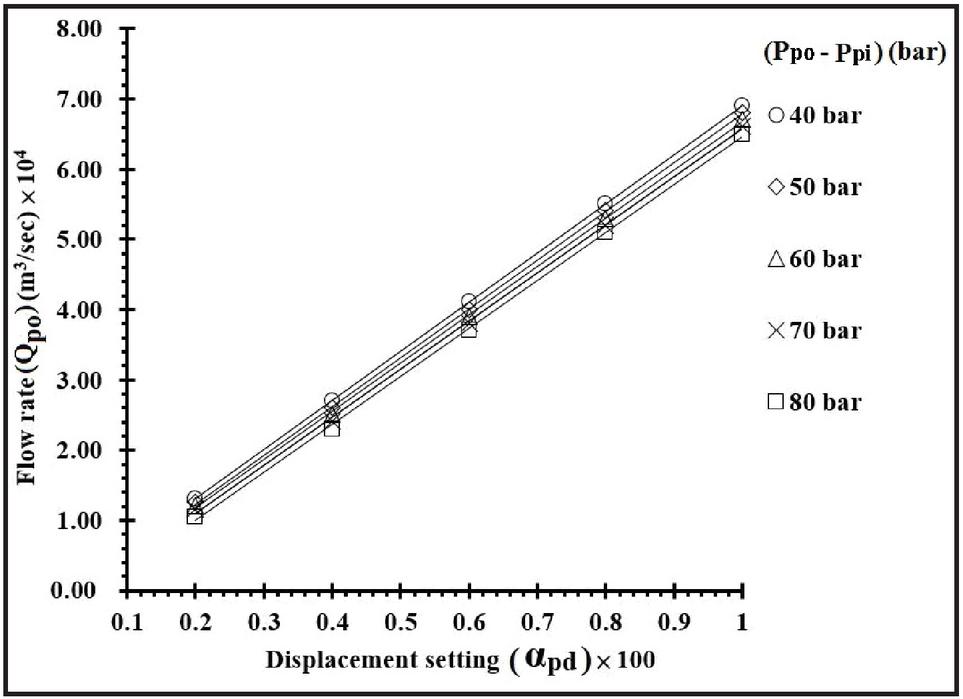
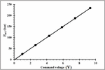
Figure 28 Variation of pump flow with displacement setting.
A2.2 Flow at Bent axis Hydro-motor with of the Bent Axis Hydro-motor
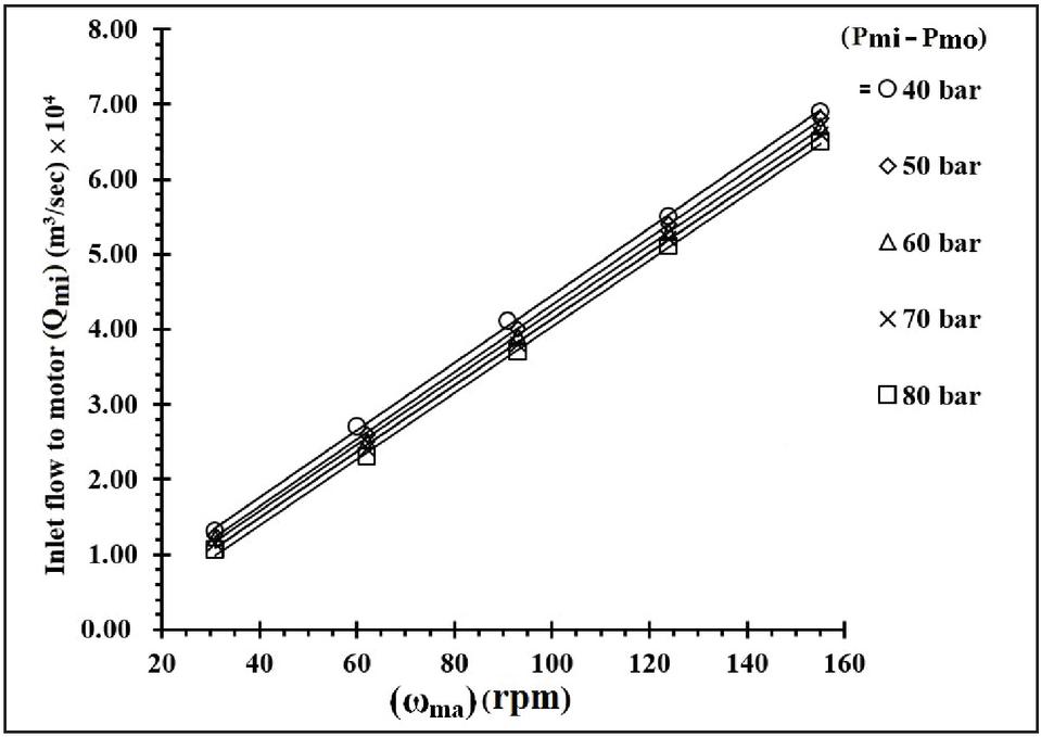
Figure 29 Variation of motor inlet flow with the speed of the bent axis hydro-motor.
A2.3 Pressure Characterization of Proportional Pressure Relief Valve (PPRV)
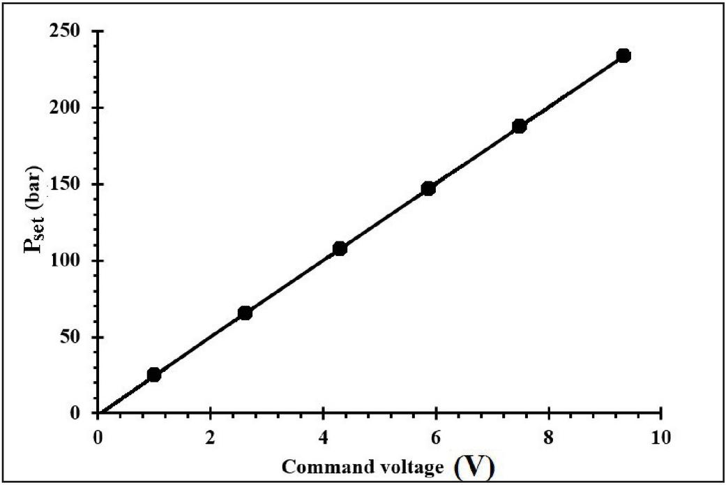
Figure 30 Characteristic of the set pressure of the PPRV.
References
[1] Manring ND, Luecke GR. Modeling and designing a hydrostatic transmission with a fixed-displacement motor. Journal of dynamic systems, measurement, and control, 1st March 1998; 120(1):45–49.
[2] Huang J, Dong Z, Quan L, Jin Z, Lan Y, Wang Y. Development of a dual displacement controlled circuit for hydraulic shovel swing motion. Automation in Construction, 1st September 2015; 57:166–174.
[3] Saber MS, EI-mashed YA, Abd Raboo S, Osman AM. Theoretical and experimental sensitivity analysis and control of hydraulic drive system. In Proceedings of the 10th ASAT conference, Military Technical Collage, Kobry EI-Kobbah, Cairo, Egypt, 13th–15th May 2003, paper GN-7, pp. 1001–1015.
[4] Sill J, Molla S, Ayalew B. Modelling and control of handling dynamics for a hydrostatically driven vehicle. International Journal of Heavy Vehicle Systems, 1st January 2011; 18(3):322–340.
[5] Comellas M, Pijuan J, Potau X, Nogues M, Roca J. Analysis of a hydrostatic transmission driveline for its use in off-road multiple axle vehicles. Journal of Terramechanics, 1st October 2012; 49(5):245–254.
[6] Huang J, Zhao H, Quan L, Zhang X. Development of an asymmetric axial piston pump for displacement-controlled system. Proceedings of the Institution of Mechanical Engineers, Part C: Journal of Mechanical Engineering Science, June 2014; 228(8):1418–1430.
[7] Song Y, Wang D, Ren H, Cai J, Jing B. Research on hydraulic pump displacement control using PI and feed-forward compensation. Advances in Mechanical Engineering, December 2017; 9(12):1–8.
[8] Pedersen NH, Johansen P, Andersen TO. Event-driven control of a speed varying digital displacement machine. In Proceeding of the ASME/BATH Symposium on Fluid Power and Motion Control, 16th–17th October, 2017, Sarasota, Florida, USA.
[9] Ding H, Zhao J, Cheng G, Wright S, Yao Y. The influence of valve-pump weight ratios on the dynamic response of leaking valve-pump parallel control hydraulic systems, Applied Sciences, July 2018; 8(7):1201–1214.
[10] Nordås S, Beck MM, Ebbesen MK, Andersen TO. Dynamic Response of a Digital Displacement Motor Operating with Various Displacement Strategies, Energies, January 2019; 12(9):1737–1747.
[11] Yan WA, Shengrong GU, Hongkang DO. Modeling and control of a novel electro-hydrostatic actuator with adaptive pump displacement. Chinese Journal of Aeronautics, 1st January 2020; 33(1):365–371.
[12] Xiong S, Wilfong G, Lumkes J. Components Sizing and Performance Analysis of Hydro-Mechanical Power Split Transmission Applied to a Wheel Loader, Energies, 2019; 12(9):1613–1631.
[13] Inaguma Y. A practical approach for analysis of leakage flow characteristics in hydraulic pumps. Proceedings of the Institution of Mechanical Engineers, Part I: Journal of Mechanical Engineering Science, 2013; 227(5): 980–991.
[14] Ozfirat, K. M., Malli, T., Ozfirat, P. M., Kahraman, B. (2017). The performance prediction of roadheaders with response surface analysis for underground metal mine. Kuwait Journal of Science, 44 (2): 112–120.
[15] Thoma, J. U. (1990). Simulation by Bond graph. Berlin Heideberg New York London Paris Tokyo: Springer-Verlag.
Biographies

Ajit Pandey is working as a Assistant Professor in the Department of Mechanical Engineering at NIT, Patna (Bihar, India). He received PhD from IIT (ISM), Dhanbad (Jharkhand, India) in 2020. He completed B.Tech degree in 2011 from MIT, Aurangabad (Maharashtra) and then served as Innovation engineer in industry till year 2012. Thereafter, he joined the PhD in 2014. He has authored many journal articles and one book chapter. His current research interests are hydrostatic transmission system, system modelling and MATLAB simulation.

Amit Kumar is working as Associate Professor and Head of Department (Mechanical Engineering) at NIT Patna (at NIT, Patna (Bihar, India). He completed PhD from Patna University in 2008, M.Tech from NIT Jamshedpur in 1999 and B.E from BIT Meshra, Ranchi in1996. He guided many PhD students and also got life membership of Indian Society for Technical Education – M. No. LM 96264. Apart from this he has authored many journal articles. His current research interests are Design, CAD/CAM and Robotics.

Nitish Kumar is working as a Assistant Professor in the Department of Mechanical Engineering at NIT, Patna (Bihar, India). He completed PhD from NIT, Patna in 2021, M.Tech from NIFFT Ranchi in 2015 and B.Tech from SEC Mayurbhanj, Odisha in 2012. He has authored many journal articles. His current research interests are characterisation of composite material and fabrication of material.
International Journal of Fluid Power, Vol. 22_3, 293–330.
doi: 10.13052/ijfp1439-9776.2231
© 2021 River Publishers