Stress Analysis of the Cylinder Block in an Axial Piston Pump
Ivan Baus1,*, Robert Rahmfeld1, Andreas Schumacher1 and Henrik C. Pedersen2
1Danfoss Power Solutions, Krokamp 35, 24539 Neumünster, Germany
2Aalborg University, Department of Energy Technology, Pontoppidanstraede 111, 9220 Aalborg, Denmark
E-mail: ibaus@danfoss.com; rrahmfeld@danfoss.com; aschumacher@danfoss.com; hcp@energy.aau.dk
*Corresponding Author
Received 28 April 2021; Accepted 30 January 2022; Publication 22 March 2022
Abstract
For axial piston units, product optimisation plays an essential role in the development phase, where an efficient and price-attractive product design and manufacturing process is the key to the success of a product. Moreover, the market needs are on lighter, more compact, efficient, and reliable products designed to the limit. Therefore, reliability is the focus of this work, where the research includes method analysis of the material stress calculation applied to the cylinder block implemented in an axial piston pump. A simplified calculation model is presented and evaluated concerning load while remaining accessible for users without deep technical knowledge or access to expensive Finite Element (FE) simulation tools. The analytical calculation method delivers a stress distribution intended for different purposes like design evaluation or as load spectrum for lifetime calculation. Additionally, the developed calculation method is generalised, enabling the methodology to be used on any standard axial piston pump. The methodology utilises the stress determination model, which includes the load as a sum of forces caused by the external and internal influencing factors. To show the method’s success, a comparison demonstrates strong positive agreement between the calculated and simulated stress results obtained by Finite Element Analysis.
Keywords: Axial piston pump, fatigue, reliability, load life, cylinder block, stress determination.
Introduction
Axial piston pumps are hydrostatic sub-systems typically implemented in heavy load applications like drivetrains and off-road vehicles’ work functions. Here, pumps are used in different sizes and performance levels as power transmission units for torque and speed conversion by generating an oil flow [1, 2]. A typical application of such a drivetrain may be found in combines, wheel loaders, or forest harvesters covered by agriculture, road building, or forestry markets. An application example covering a wheel loader using axial piston pumps is shown in Figure 1. In these types of applications, an axial piston pump is typically used in the drivetrain. In the centre of the picture, a cut through pump shows the rotation kit’s position. The rotation kit is the core subassembly consisting of high-end components, which typically are designed to the limit. Hence, nearly all sub-components are affected by the tough environmental and load conditions of these machines. Therefore, it is essential to ensure a reliable operation over the whole service life, where different approaches exist [3–5].

Figure 1 Application example of an axial piston pump implemented in a wheel loader.
In a drivetrain, a typical hydro-mechanical power transformation starts from the engine and goes over internal components of an axial piston pump like the shaft, various bearings, some pistons, the cylinder block, and results in oil flow. These components belong to the sub-assembly, often called the “rotation group” [1]. Due to the high-performance requirements and the harsh conditions of the system and environment, axial piston pumps have increased complexity in design, resulting in increased simulation effort, load capacity verification, and product evaluation [6–9]. Thus, during the design specification and development phases, it is essential to achieve the goals of maximum load capacity while fully utilising the material potential and at the same time keeping power losses in the system as low as possible. As the units are complex, this has typically called for advanced FE-simulation studies, where expensive tools generally are used [10].
However, performance analysis, design evaluation, and verification processes may require many iterations. Therefore, more efficient and cost-attractive methods are required that still adequately describe the components’ loading. Not least, due to the complex relationship between load and impact to the entire systems, and hence the reliability of the components. The method efficiency may be rated by the correlation between analysis costs (time, effort, tool costs) to accuracy result.
Therefore, the aim of this work is to develop and evaluate a simplified analysis method concerning material stress applied to the cylinder block splined hub implemented in an axial piston pump. Based on the Failure Likelihood Analysis (FLA) [11, 12], previous studies have shown that the cylinder block has a certain fatigue failure probability, implemented in applications with demanding alternating stresses [12]. The cylinder block failure mode covers the splined hub’s fractures due to fatigue loading. Therefore, the focus of the current work is therefore on the splined hub, where the stress analysis of the load factors was performed. Due to the complex design and operation surrounding the cylinder block, an analysis of loads is often very demanding. Those typically cover the varying loads, including forces, temperature, vibration, and others. Hence, this is driven by the failure’s impact on the entire system from a reliability assessment point of view. As material stress of a component is often design specific, the method presented in this paper is component-type specific and may be applied to a cylinder block only. It should be mentioned here that this work is an integrated part of a lifetime research focus, where the nominal lifetime is given by the (characteristic) reliability of a component covering the “stress to load” relation. Therefore, stress analysis is required to create a detailed and accurate picture for design and lifetime analysis.
Novelty of This Work
Nowadays, stress analysis is typically done using FE-Tools like ANSYS. This section discusses the advantages and disadvantages of FEA and the simplified calculation model (further referred to as analytical analysis). A typical disadvantage of FEA-Tools covers a deviation due to the simulation using an ideal 3D-Model. Here, the consequential product tolerances caused by production processes are often neglected. Also, a rough setup of the sample mesh or gross load simulation steps may lead to inaccuracy in results. An additional disadvantage may be the user’s subjective elaboration due to low realistic physical boundaries restrictions. Hence, proper success still relies on the user’s high expertise level for both the analysed product (including environment) and FEA-tool [13]. Moreover, the simulation requires a much longer execution time than case-specific analytical solutions. An analytical analysis significant advantage may be the simple and fast implementation and proceeding of the methodology in other approaches or tools after the final evaluation. Using an analytical approach during the design optimisation, a time-consuming proceeding of FEA may be avoided in the first phase of a development process, which may be valuable. One of the main advantages of the analytical methods is the time effort reduction during further use of the analytical calculation model. That means that material stress results can be delivered in seconds from the second calculation run, while simulation tools must be prepared or modified and often have a long computing time. The time effort, and costs of the simulation tools are exceeded by experimental evaluation only, where often cost-consuming hardware runs over many hours or days.
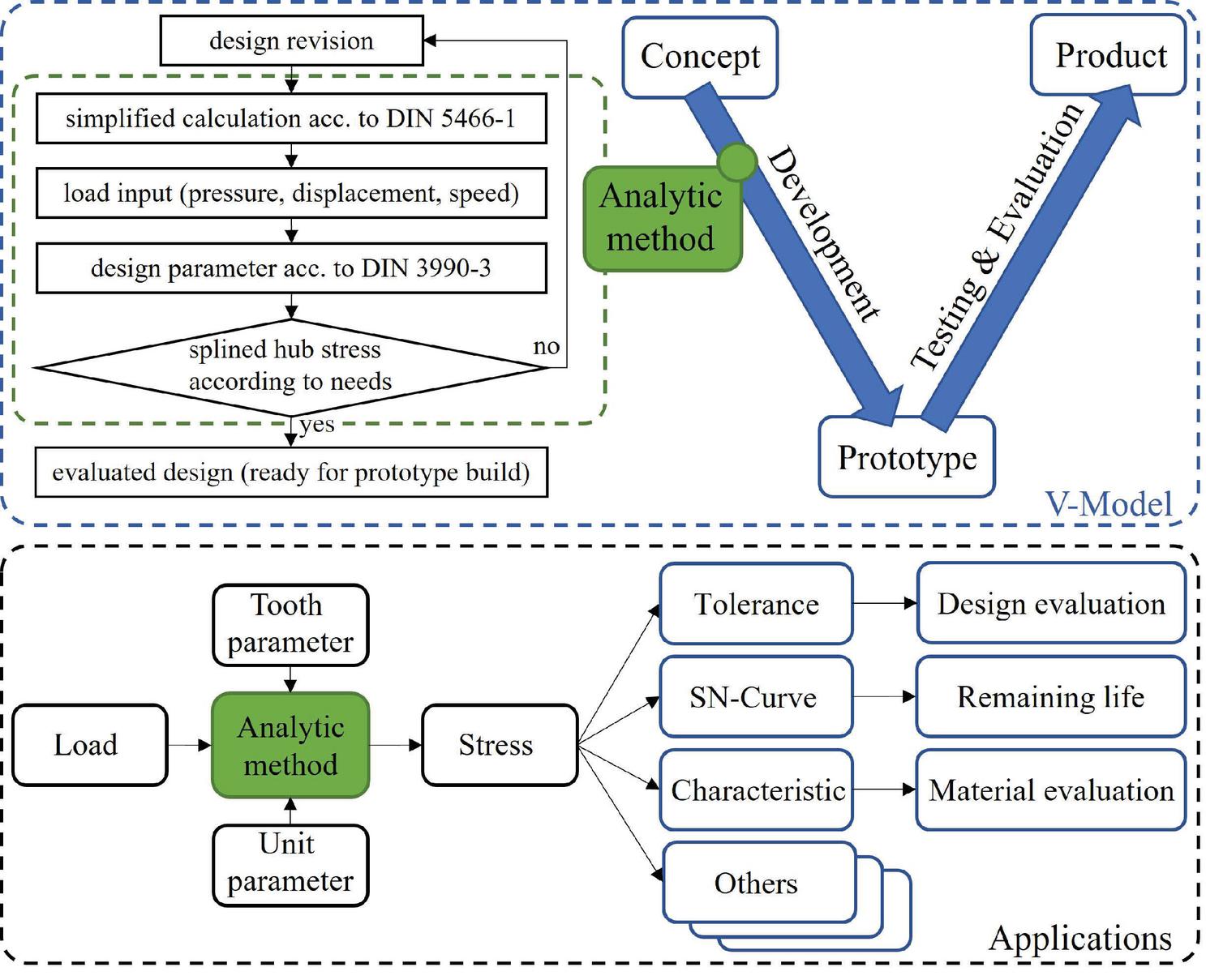
Figure 2 Proceeding of analytical stress analysis integrated in a V-model and few application examples.
Still, the final design optimisation phase does not exclude an additional (effort reduced) FEA analysis by previous analytical analysis to gain the last bit of a product efficiency or accuracy. Nevertheless, it should be mentioned here that an analytical solution might be case-specific, and an application to another product type of use often requires modifications, which is the disadvantage of a mostly fixed analytical model. Additionally, the analytical calculation model simplification may lead to a certain degree of inaccuracy. However, as soon as an analytical model is defined and validated, it may be used in different functional areas without expert knowledge. Hence, in contrast to the powerful FEA, analytical procedures can be made available for people without an engineering background. This opens new opportunities for use, and the analytical method may be applied as a calculation code or procedure for different purposes like product evaluation or optimisation, costing, maintenance planning, etc. Therefore, users without deep technical knowledge or access to simulation tools outside of the engineering department (Sales, Service, etc.) can benefit from the analytical solution. However, the applicability of the method results is very diversified and may be used in product design evaluation and optimisation. For example, the experimental effort involved in product evaluation may be significantly reduced as an analytical method is able to deliver accurate results.
The implementation of the analytical stress analysis method into standard engineering processes can be done by using the generally known and often used V-model as a lifecycle development diagram.
Here, the analytical method can be performed in the early phase of the development process, where a design revision is delivered from the concept build and must often be analysed concerning the stresses. As soon as the method algorithm is developed and verified according to DIN 5466-1, the specific parameters shall be extracted from the concept design according to DIN 3990-3. Then, with an expected or known load spectrum, the calculation may be easily completed, as shown in Figure 2.
The novelty of this work includes not only the analysis of the cylinder block splined hub related to the material stress itself but also the applicability verification of generic standards DIN 5466-1 [14] and DIN 3990-3 [15] for this kind of application and operating conditions. Hence, the material stress calculation method was implemented as a simplified analytical model. However, even if these standards deal with load capacity calculation of toothed and splined shaft connections, the cylinder block splined hub is not a typical application with a slightly different context. Therefore, the applicability evaluation of the simplified model is basically related to the result deviation compared to the FE-analysis.
Cylinder Block Investigation and Its Failure Mode
The FLA and the experimental analysis in [11, 12] showed with a high agreement that the cylinder block is the main component related to fatigue relevance in demanding applications. The application and design-specific impact of the cylinder block to an entire system can be seen in Figure 3, where the influencing factor is shown in a failure probability plot in percent. It should here be noted that it does not mean that the cylinder block is designed to be weak. On the contrary, the cylinder block hub is highly loaded by forces and moments. On the other side, it is geometrically designed to the limit due to limited space and firmly contained to thin wall thicknesses by the pistons, guide ball, and slipper hold down. Thus, it means that the component is highly loaded, leading to a certain number of failures in a system or rather to the observed system’s shortest service life. In other words, a cylinder block may have the highest failure probability due to acting loads related to design and application and can be a significant factor of the service life limitation.
Based on endurance tests and its operation conditions, the experimental results showed a failure probability of the cylinder block with of the whole pump defined as , as shown in Figure 3. includes the failure probalility of all other sub-components of the axial piston pump.

Figure 3 Unreliability plot of a pump as divided in and .
Hence, the experimental investigation confirmed the FLA results [12], which substantiate the component’s failure probability expectation in an axial piston pump. During testing at extremely high load conditions, the cylinder block splined hub was the most damaged area of the cylinder block. The failure type of the splined hub suggests that fractures start in the root of some teeth caused by acting forces, which lead to material stress and is the root cause for fatigue fracture. A few fracture examples are shown in Figure 4.
A typical key factor of the unit assessment in the industry is the nominal lifetime, expressed in load cycles or operating hours. The nominal lifetime is indicated as and defined as the point where 10% of the units may fail due to fatigue effects, as shown in Figure 3. At the point of , the experimental analysis shows that the splined hub failures have greater weighting compared to the final value of the and is given by:
| (1) |
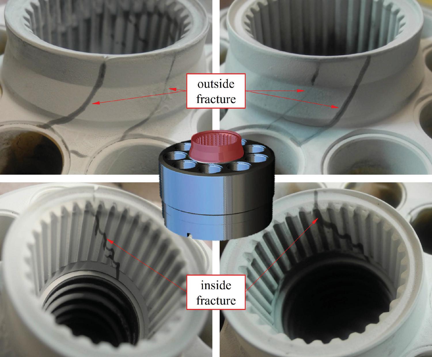
Figure 4 Exemplary damages of the cylinder block splined hub highlighted by dye penetrant inspection.
Based on these unreliability results, the next logical step is to analyse the splined hub in case of stress impact and grade. The analytical analysis was derived from the DIN 5466-1 and DIN 3990-3 standard in this work. These standards are typically used a.o. for calculation of load capacity of splined joins and cylindrical gears.
Stress Determination of the Cylinder Block Hub
As the cylinder block is the component with the highest fatigue failure probability with a significant gap to the second component, the internal alternated load on the cylinder block splined hub is of interest. Two different methods are used in this work for calculation and evaluation of the material stress, where the first covers an analytical approach and the second covers the FEA simulation using ANSYS. While the analytical calculation is related to the DIN 5466-1 and the DIN 3990-3 standards and is based on a simplified calculation model, the FEA-simulated values are used as a reference for the validation purpose of the analytical results in this work. Therefore, all shown data and system figures in this section are related to the experimental conditions.
Introduction of the DIN 5466-1 Applied to a Cylinder Block Splined Hub
The purpose of this standard is the uniform calculation of the load capacity and wear-out behaviour of the splined shaft and hub connections. The influencing variables in this standard are based on research results and operational experience recorded, like:
• External loads due to torque
• Internal loads, a.o. lateral force, axial force, and bending moment
• Design stack up or rather component tolerances
• Elastic behaviour of the connections or rather interfaces
• Lubrication and wear of flank connections
With this, the standard contains methods for estimating the effective loads on the tooth flanks, the flank stress, the wear behaviour, and an approach calculating the stress in the notched area (tooth root) of the shaft and hub. The method’s use requires a realistic assessment of each application’s influencing factors, particularly the permissible loads, the appropriate risk of damage, and the corresponding safety factor.
The load of the splined hub consists of different factors. However, DIN 5466-1 deal with load factors reduced to the significant forces acting between shaft and hub, as shown in the free body diagram in Figure 5. The sum of forces acting on the teeth flanks are comprised in the axial force , the radial force , axial torque and tilt torque .
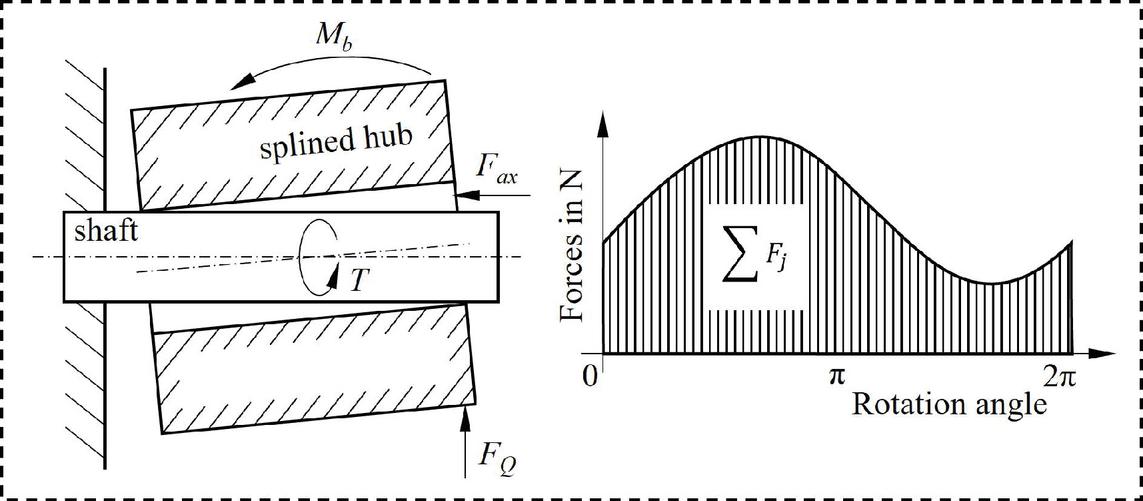
Figure 5 Standard forces of the DIN 5466-1.
However, for the spline hub, the axial force and tilt torque may still be neglected with reasonable accuracy, whereby the implemented factors are reduced to radial force and axial torque. The background for neglecting the cylinder block’s tilt forces is that they are transferred to the gap between the cylinder block and valve plate with the hydrostatic bearing balances combined with the crowned design of the shaft teeth. Therefore, the tilting torque has only an insignificant load influence on the cylinder block splined hub. The axial forces cover low friction forces only and may be neglected as well. As the z-axis-motion is small, the lubrication between the hub teeth and the shaft teeth only leads to small friction forces. In the following, the notation is used for the radial force and as the axial torque acting on the splined hub, to follow the generic nomenclature used in hydrostatics literature. Due to the high rotation speed of the cylinder block, the centrifugal force should also be considered, as shown in Figure 6.
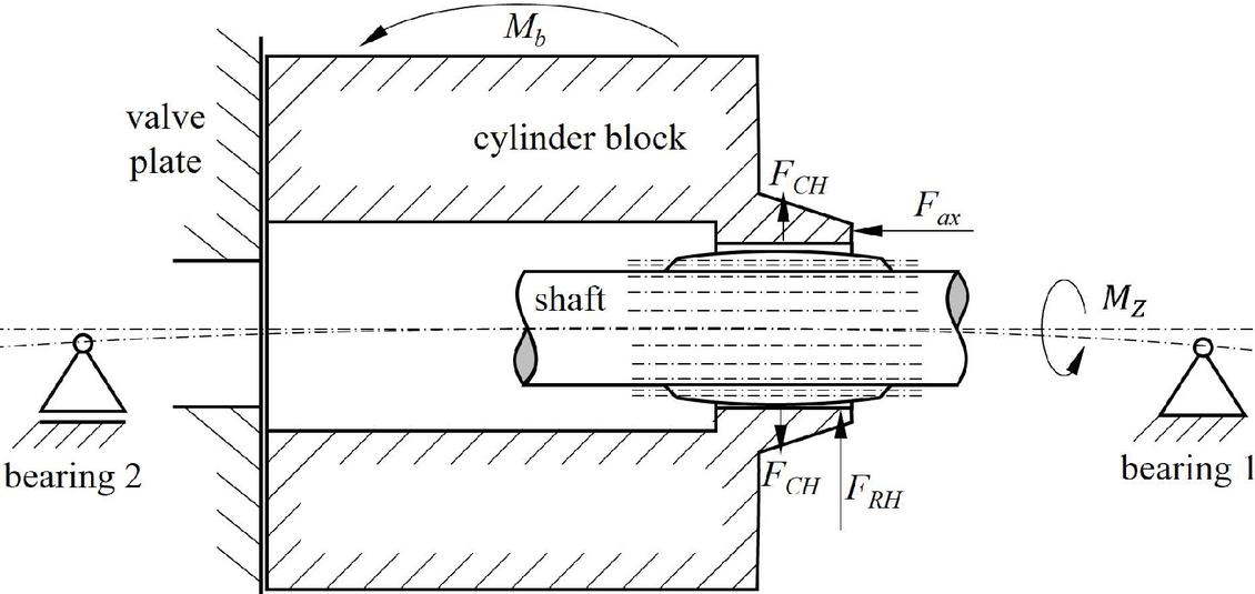
Figure 6 Conceptional application of DIN 5466-1 to cylinder block implemented in an axial piston pump and force tendency.
Forces Calculation
The effective forces acting in a cylinder block may be divided into two basic types; the first and most relevant type is the pressure-dependent forces, whereas the second type covers the pressure-independent forces. While the pressure-independent forces include inertia forces, gravitation, etc., the pressure-dependent forces are caused by system pressures. Due to the high impact of the pressure-dependent forces combined with small pressure-independent forces, the latter may be neglected, with an acceptable loss in accuracy [16]. All pressure-independent forces except the centrifugal force are therefore excluded in this work. For example, the frictional forces are too low due to oil lubrication, or the inertia force is equal to zero due to stationary speed. In this work’s case, the forces and the material stress were analysed at steady-state conditions, where the operating conditions were constant. Hence, during the testing procedure, the focus has been to ensure a constant load of the cylinder block splined hub by steady-state conditions. Therefore, many factors were significantly reduced in their impact. This means that the operation conditions like rotation speed, displacement angle, charge pressure, oil temperature and viscosity, environmental temperature, etc. are unchanged during the testing run . Therefore, an additional method validation of the analytical approach under dynamic/varying loading requires further work.
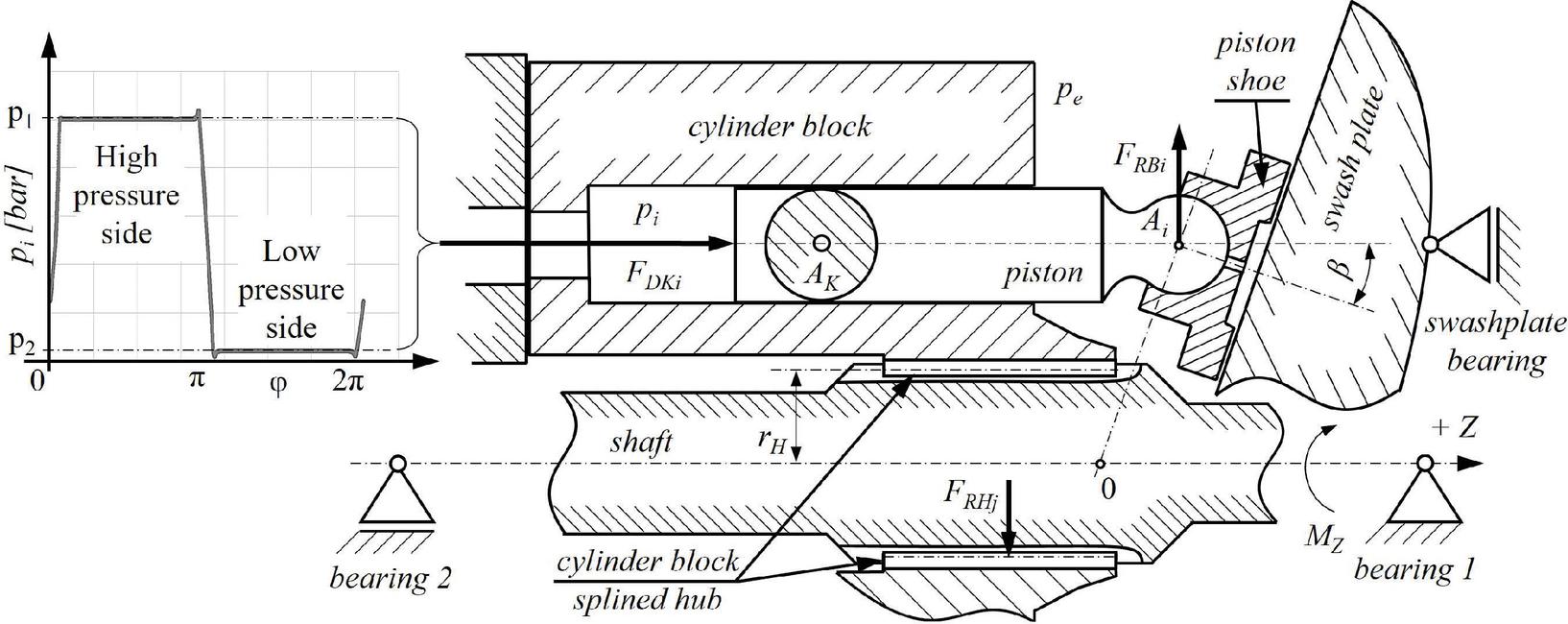
Figure 7 Schematic diagram showing the pressure acting in a single cylinder dependent upon the angular position of the rotation.
Although the system pressure can be seen as stationary, each cylinder’s pressure has an alternating behaviour, which leads to alternating forces in the system. Hence, these forces are introducing the alternating stresses concerning the fatigue-related problems and focus in this work in the form of material stress impact. Caused by alternating pressure forces during one rotation and considering the swashplate angle dependency, the radial, torque, and centrifugal forces are important and used for the stress analysis.
The alternating pressure in a single cylinder bore during one rotation covers the external load and may be seen in Figure 7. The same pressure curve was used for the analytical and simulation analysis as well as for the experimental evaluation. For both the analytical analysis and FE-simulation, the swash plate displacement angle was set to maximum, due to the highest stress impact at the extreme position.
Starting with the pressure force acting on a piston, is given by:
| (2) |
where is the effective piston (pressurised) area, is the instantaneous pressure acting in the cylinder bore with the corresponding angle and steady-state housing pressure as shown in Figure 7.
When investigating the relevant forces acting on a cylinder splined hub, the forces may be split in the X, Y and Z-directions, as shown in Figures 7 and 8. Neglecting frictional and inertia forces, the only components acting perpendicular to the cylinder block axis Y consists of the force acting on the cylinder block as radial force rising with angle .
| (3) |
As frictional and inertia forces are neglected for all k pistons, the sum of the radial forces may be applied:
| (4) |
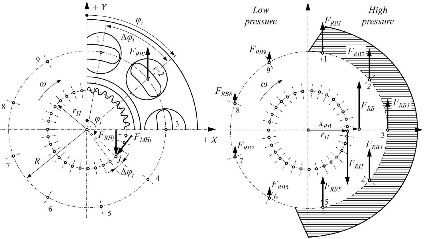
Figure 8 Points of action related to radial forces of a cylinder block.
Due to the high pressure acting on one side and low pressure on the other side in the cylinder block, as shown in Figure 8, the resulting force covers both the radial and tangential vectors. Note that is following a path with a complex trajectory in the form of an eight and is not fixed in a point with a constant vector .
Hence the following applies:
| (5) |
The transfer of the cylinder block force to the hub force may be done by using the torque ratio and is given by:
| (6) |
In the case of a dominant radial force with the corresponding lever arm, the load distribution shifts with a corresponding ratio. The splined hub related radial force may be distributed over the number of teeth as a normal force which can be calculated by the following equation:
| (7) |
In this connection, it should be noted that the load distribution is dependent on the geometric orientation of cylinder block boreholes relative to the orientation of splined hub teeth and is therefore design specific. This should be taken into account if a specific orientation of the tooth to the cylinder block boreholes is to be analysed. In this work, only the worst-case orientation with the highest material stress was in focus. Moreover, the distribution of is dependent on the transfer form from the shaft to hub, where the orientation (flanks-oriented) and the clearance between the tooth of the shaft to hub should be taken into account.
While radial forces are oriented against the opening displacement angle and distributed considering the tooth angle with tangential and radial vectors, the torque forces may be constantly distributed over the whole rotation. The torque resulting from the forces acting tangentially on the hub teeth may be calculated by using the torque , which is given by the following equation:
| (8) |
With V as the actual volume related to the displacement angle.
| (9) |
With this, knowing the torque acting on the shaft axis and the assumption that the torque-related forces are distributed evenly, it is possible to calculate the force resulting from the split torque for every single tooth using the following equation:
| (10) |
The centrifugal forces caused by the rotation speed of the cylinder block subassembly and transmitted as to the normal orientation of the single splined hub tooth is determined from:
| (11) |
with as centrifugal force, as the mass of the affected sub-assembly including pistons, as the pitch diameter of teeth, as tooth angle, and as angular velocity.
| (12) |
As the force can be seen as applied in the tooth centre , the sum of the forces for every single tooth may be found by summing Equations (7), (10), and (11). For the tooth with the j’th position, it yields:
| (13) |
The force acting on the tooth as the primary load force is used in the next sub-chapter to calculate the material stress.
Stress Calculation by Using Simplified Method C According to DIN 3990-3
The splined hub’s stress is usually characterised as a result a.o. of torsion and centrifugal forces, tooth bending, bending perpendicular to the hub axis, pressure and axial force, or relative displacement of the shaft and splined hub by axial tension or pressure. However, based on the considerations and simplifications described above, several of these terms may be neglected, because the influencing factors are limited to the displacement-related (radial), torque-related (tangential), and speed-related stress (centrifugal). Therefore, the resulting hub stress in the root area is converted from the individual partial stresses into an equivalent stress component. The stress distribution was analysed over the rotation and tooth length, as shown in Figure 9.
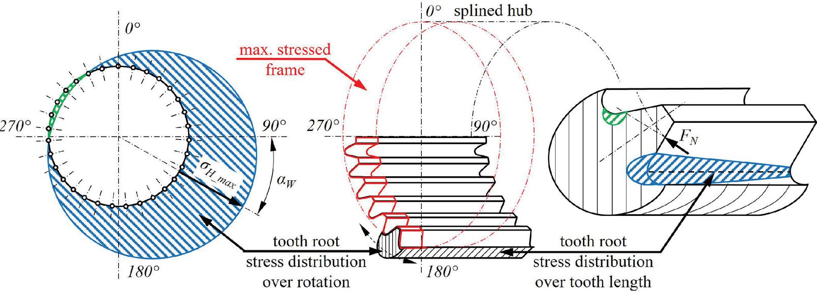
Figure 9 Material stress distribution of the splined hub root over the rotation and length.
Considering one rotation of the splined hub, the stress distribution for a single point follows a sinus-like waveform. However, in the DIN 3990-3-C, the stress distribution is described with the Equation (14). Here, the material stress is a function of the rotation only. Therefore, the material stress is given by:
| (14) |
with b as the width of the tooth, as a form factor for the tooth design, as the sigma correction factor, as overlapping factor and m as the module of the splined hub. The factors and used in this work were calculated directly by using DIN 3990 standard. The value of b is given by tooth design, and the module can be calculated by using pitch diameter and the number of teeth :
| (15) |
However, the splined hub stress calculation is complex due to the multi-dimensional vectors, where the insufficiency of the DIN 3990-3 simplification becomes visible. In this standard, the overlapping factor is related to constant transverse contact ratio which insufficiently describing the hub stress distribution of flank-centred contact interface between hub and shaft tooth with the existing gap in-between.
| (16) |
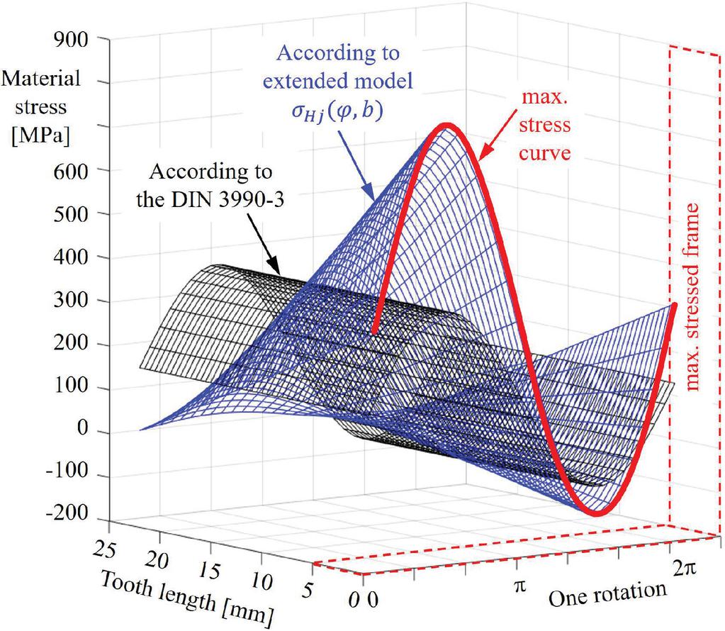
Figure 10 Illustrative material stress distribution over tooth length and one rotation.
In particular, this analysis was done using involute profile splined hub with standard straight-sided flanks manufactured by hobbing, as it is covered by DIN 5480 [17]. In the case of other designs, the distribution may require additional analysis and modifications.
Therefore, the overlapping factor should be described as a function of the rotation angle and the tooth length. In this work, the overlapping function was expected as increasing linear distribution due to design, like shown in Figure 10, and was verified by the FE-Analysis with a minor deviation for the maximum peak stress in the worst case.
| (17) |
with as the modified overlapping factor is given by:
| (18) |
whereby is the coordinate of the tooth length.
As the calcuated force covers the whole rotation of 360 degrees and is split to the number of the load-affected teeth in the hub; the tooth root stress can be shown distributed over the whole rotation also. In the next step, the determined stress distribution may be sorted as a load spectrum from high to the low load of every single tooth during one rotation, as shown in Figure 11, which has also been compared and verified by FE-simulated results. In this work, a cylinder block with 31 teeth was used for analysis purposes. The load spectrum distribution has a step-like behaviour due to the alternating hub load’s switching by the odd number of pistons and due to the discretised calculation divided by the number of teeth. A recalculation to a higher resolution than the number of teeth is also possible if the calculation is done for every single degree of a rotation instead of a calculation for teeth angle .
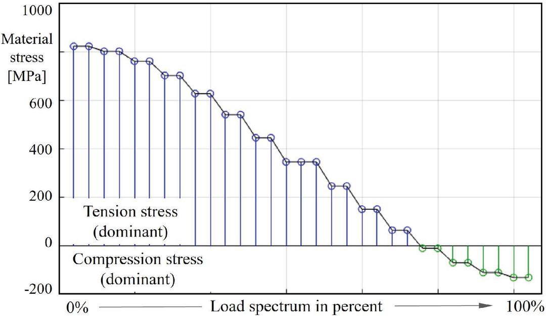
Figure 11 Material stress distribution sorted in descending order as load spectrum.
With the above mentioned, the simplified analytical modelling and the calculations are complete. The determined material stress curves for different load situations may be used to calculate the component’s equivalent fatigue loading. This presented analytical approach is validated in the following sections by comparing the obtained results with those from full FE-simulations of the same spline hub using ANSYS.
Stress Simulation by Using FEA and Comparison of Results
As described in the introduction, the experimental validating methods of tooth stresses are often complex and expensive. However, FE results have been shown to provide very good measures for describing the stresses in these systems. In the following, the stress analysis of the cylinder block splined hub is analysed through the Finite Element Analysis (FEA) for structural analysis using the ANSYS Mechanical Interface. Among others, this tool covers a range of applications like geometry preparation and optimisation.
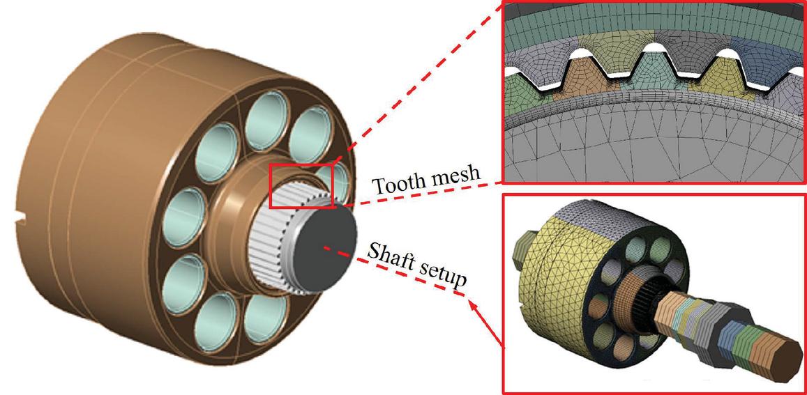
Figure 12 Cylinder block mesh and the simulation sub-assembly of the FE-Analysis (different mesh resolution was used; only areas of interest had adequate resolution).
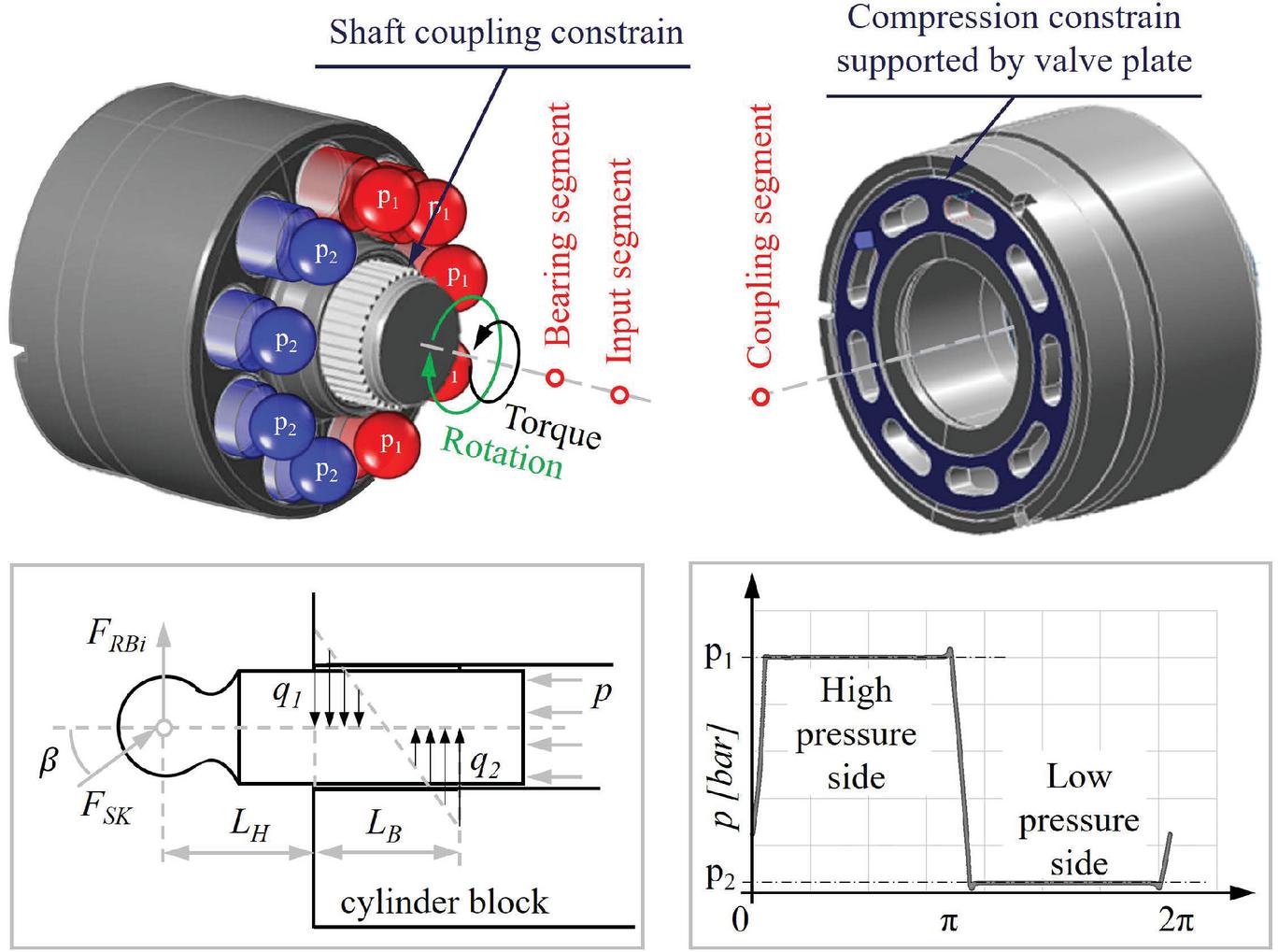
Figure 13 Subcomponents constrains, pressure simulation and material stress distribution of the FEA setup.
The boundary conditions of the FEA simulation may be seen in Figure 13, including the rotation and torque directions. The positions, or rather the coordinates of the influencing segment are illustratively shown as well. Here, it should be mentioned that the correct positioning of these segments before a simulation is crucial while substantially influencing the force calculation. Additionally, the viscosity and friction are represented by the simulated pressure behaviour in the piston boreholes. The pressure signal simulation was done by using a comprehensive mathematical model of the complete axial piston unit.
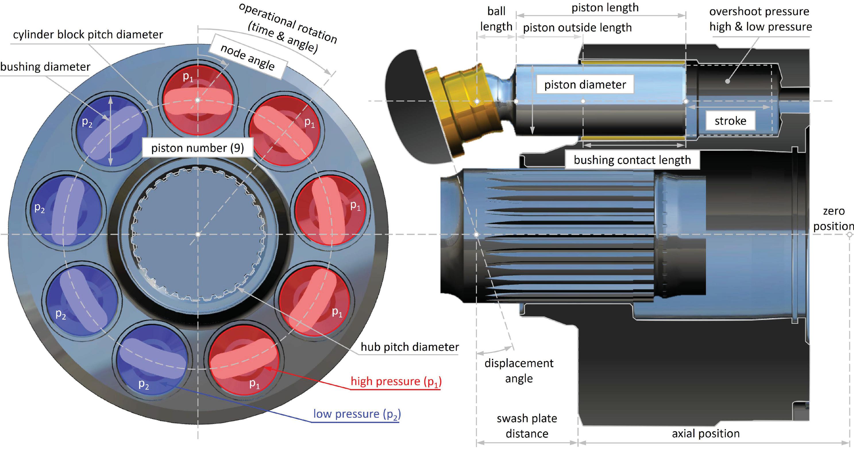
Figure 14 Significant influencing factors of the FEA simulation.
The most relevant factors are included in Figure 14 and cover the significant material and design characteristics, describing the analysed system as detailed as required for an entirely determined picture. Using the same 3D model for the FEA analysis, as developed for the manufacturing, promises results that are as near as possible to reality.
The purpose is to verify the analytical results, as described in the previous section. The simulated results of this tool have been proven extensively, so it can be expected that the results have a high confidence level. The simulation’s model preparation is of the utmost importance to ensure the right and realistic setup, as demonstrated in Figure 12. Thus, the assembly’s design and physical interdependencies must be taken into account, considering that the analysis may cover different forms of stress, natural frequency, or deflection of a part under load.
The simulation outcome usually includes different results like material stress level, contact distribution, and deformation grade. Among load input, the setup of the simulation includes mesh-detailing and shaft definition, as shown in Figure 12. However, in this work, the stress level is of interest, so this is the only parameter compared to the two methods.
The model mesh has to be kept constant for the whole loading cycle for the stress calculation. Therefore, instead of rotating the block and shaft, the loads were rotated. Five and four pressurised pistons were included in the case-switch, respectively and the rotation was split into 18 simulation steps over one revolution. After the simulation of one revolution in one direction, it was performed for the opposite side, where the same load cycle was repeated for the opposite direction. One revolution covers an overview of complete material stress and is required for future work, covering, among others, the calculating the mean effective stress using SN-curve. The simulated results may be seen in Figure 15. Every single distribution covers 31 teeth stress points, which mainly occurs due to different relative orientations of the 31 teeth to the 9 piston loads.
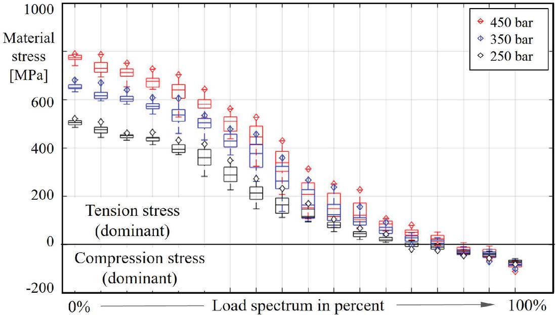
Figure 15 Simulated stress spectrum related to the absolute pressure .
The radial and axial forces on the piston were calculated based on geometry, swashplate angle, and system pressure to compare the results. The pressure distribution between the piston and cylinder block was derived from the radial load. It was calculated for each piston based on the swashplate position and piston position concerning the cylinder block. Finally, the pressure distribution was defined by a macro in the FEA model. To ensure the load correctness, the moment around the axis of rotation and the sum of all transversal forces were evaluated with every time step/update.
Considering the simulation results in Figure 16, it becomes clear that the load distribution coincides with the described analytical model. Additionally, it should be noticed that the graphical result of the FE simulation shows an extremely exaggerated bent for the illustrative purpose of the forces only.
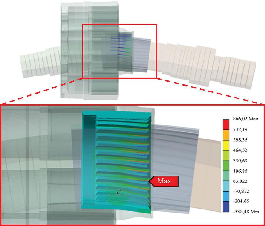
Figure 16 Graphical result of the ANSYS simulation (illustrative exaggerated bending).
The evaluation of the analytical approach was done for different operations conditions, where the various absolute maximum pressure was applied, as shown in Figure 17. Comparing simulated (FEA) and calculated (analytical) results show that the analytical approach’s results deliver sufficient material stress distribution accuracy. Furthermore, the calculated results have excellent conformity with the maximal simulated stress distribution in both orientations (tension and compression) and under all load situations. Therefore, the method delivers a good overview of the worst-case stress level based on the given operating conditions, which will be the basis for future fatigue and reliability calculations.
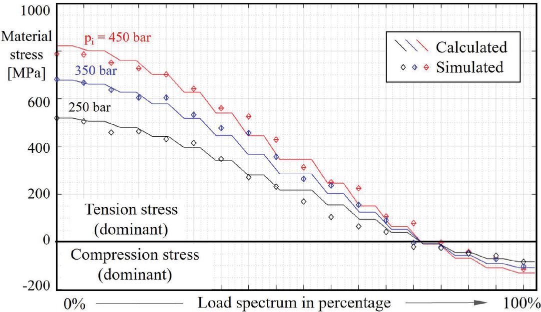
Figure 17 Spectrum comparison of the calculated (analytical) max. stress with simulated (FEA) max. stress for different pressures in the cylinder bore hole.
Conclusion
In this work, the material stress of a cylinder block was analysed implemented into an axial piston pump. The analytical calculation method is based on a simplified calculation model for the determination of forces and the stress calculation, including the addressing of the simplification grade to get the required result accuracy. The method was shown to produce results with excellent agreement relative to an advanced FE-model when considering the tooth stress’s maximum load and load distribution. The evaluation of the calculated stresses was successfully done for different load/pressure levels with the same excellent agreement. The novelty of this work includes not only the analysis of the cylinder block splined hub related to the material stress itself but also a good applicability of generic standards DIN 5466-1 [14] and DIN 3990-3 [15] using simplified analytical model and modifications to account for a non-constant overlapping. Even if the cylinder block splined hub is not a typical application as described in those standards with a slightly different context, high confidence could be reached in calculation results by required modification according to design. Hence, the analytical method creates an analysis option that is fast and enables people without in-depth expert knowledge of load capacity calculation of cylindrical gears to do the calculations.
Outlook
With this work, an essential part of performing lifetime calculations of axial piston units is defined. Moreover, the analytical method could easily be generalised to an extended range of units. So, the parameters like pitch diameter, module, tooth length, or the number of teeth can be scaled to deliver results for different product sizes as well. Therefore, the results are also suited to be used for product optimisation, design validation, or other purposes. Once implemented, the analytical calculation model may be used for analysis purposes in different cases and variations (unchanged design required). Additionally, the analysis using this analytical approach is to be seen as a preceding research step for a possible analysis of lifetime research. Hence, the analytical model could easily be implemented in tools/frameworks to calculate the remaining life using approaches like e.g. the Palmgren-Miner or Miner modified according to Haibach methods.
Nomenclature
| pressurised area of a piston | |
| action point of the th ball-joint | |
| tooth width | |
| pitch diameter | |
| axial force | |
| alternating force in a single cylinder bore | |
| radial force of the cylinder block | |
| radial force of the splined hub th tooth | |
| normal oriented radial force part related to tooth surface | |
| torque force of the spline hub th tooth | |
| normal oriented torque force part related to tooth surface | |
| centrifugal force acting on the th tooth | |
| normal oriented centrifugal force part related to tooth surface | |
| sum of all forces acting on the th tooth | |
| reaction force of the swash plate | |
| unreliability function | |
| unreliability of a cylinder block | |
| unreliability of a pump | |
| unreliability of sub-components | |
| th piston | |
| th tooth | |
| number of pistons | |
| length of the piston (H outside of the cylinder block, | |
| B bushing contact) | |
| module of the splined hub | |
| torque of the cylinder block | |
| radial torque of the cylinder block | |
| mass of a sub assembly | |
| pitch radius of the cylinder block | |
| material stress distribution over a bushing contact surface | |
| pitch radius of the splined hub | |
| radius of acting radial force | |
| alternating pressure | |
| housing pressure | |
| absolute pressure | |
| charge pressure | |
| actual volume | |
| maximal volume | |
| overlapping factor | |
| form factor | |
| sigma correction factor | |
| number of teeth | |
| tooth angle | |
| maximal stress angle | |
| swash plate displacement angle | |
| maximal displacement angle | |
| transverse contact ratio | |
| material stress of the th tooth root | |
| rotational angle | |
| angular acceleration |
References
[1] Ivantysyn J., Ivantysynova M., “Hydrostatic Pumps and Motors: Principle, Design, Performance, Modelling, Analysis, Control and Testing”, abi, 2001
[2] Totten G.E., De Negri V.J., “Handbook of Hydraulic Fluid Technology”, Chapter 1.4 Hydraulic Components, ISBN 13: 978-1-4200-8527-3, 2012
[3] Li T., Wanga S., Zio E., Shia J., Ma Z., “A numerical approach for predicting the remaining useful life of an aviation hydraulic pump based on monitoring abrasive debris generation”, https://doi.org/10.1016/j.ymssp.2019.106519, 2019
[4] Zio E., Peloni.G, “Particle filtering prognostic estimation of the remaining useful life of nonlinear components”, Politecnico di Milano, 2011
[5] Li H., Sun J., Ma H., Tian Z., Li Y., “A novel method based upon modified composite spectrum and relative entropy for degradation feature extraction of hydraulic pump”, https://doi.org/10.1016/j.ymssp.2018.04.040, May 2018
[6] Jähne H., “Antriebsstrangkonzepte mobiler Arbeitsmaschinen” in “Schriften-reihe der Forschungsvereinigung Bau- und Baustoffmaschinen”, Dresden, 2006
[7] Sturm C., “Bewertung der Energieeffizienz von Antriebssystemen mobiler Arbeitsmaschinen am Beispiel Bagger”, Dissertation, KIT, 2015
[8] Kautzmann T., “Die mobile Arbeitsmaschine als komplexes System”, Dissertation, KIT, 2013
[9] Fleczoreck, T.: Effizienzbewertung von Antrieben mobiler Arbeitsmaschinen am Beispiel eines Mähdreschers. Dissertation, TU Braunschweig, 2013.
[10] Rao. S.S., “The Finite Element Method in Engineering”, Elsevier Science & Technology, 2004
[11] Baus I., Rahmfeld R., Schumacher A., Pedersen H.C. “Systematic Methodology for Reliability Analysis of Components in Axial Piston Units”, Symposium of Fluid Power and Motion Control (GFPS), Sarasota, USA, October 9th, 2019
[12] Baus I., Rahmfeld R., Schumacher A., Pedersen H.C. “Lifetime Impact Prediction of Component Modifications in Axial Piston Units by the Failure Likelihood Assessment”, IFK, Dresden, Germany, October 2020
[13] Pavlou D. G., “Essentials of the Finite Element Method: For Mechanical and Structural Engineers”, Chapter: “An Overview of the Finite Element Method”, Elsevier Science & Technology, 2015
[14] DIN 5466-1, “Splined joints, calculation of load capacity”, October 2000, International relationship: GB/T 17855 (1999), NEQ
[15] DIN 3990-3, “Calculation of load capacity of cylindrical gears; calculation of tooth strength”, 1987, International relationship: ISO 6336-3 (2006-09), NEQ
[16] Ivantysyn J., Ivantysynova M., “Hydrostatic Pumps and Motors: Principle, Design, Performance, Modelling, Analysis, Control and Testing”, Chapter “Forces and Torques”, third paragraph, page 134, abi, 2001
[17] Stadtfeld H.J. “Design Parameters for Spline Connections” Gear Technology, https://www.geartechnology.com/articles/0919/Design\_Parameters\_for\_Spline\_Connections, September/October 2019
Biographies

Ivan Baus is a PhD fellow at the Aalborg University, and his research field is the lifetime prediction of axial piston units. Ivan has been with Danfoss for over 10 years, operates in various development & research projects, and has several scientific publications. In the Research and Development team, his focus is on axial piston units for mobile applications covering the expertise and responsibilities of Condition Monitoring and Embedded Controller Solutions.

Robert Rahmfeld is the Senior Director Engineering for Hydrostatics at Danfoss Power Solutions, being technically responsible for all hydrostatic axial piston units, including swash plate and bent-axis principle. He is with Danfoss over 15 years in various engineering positions, holds several patents, and is author or co-author of more than 50 scientific journal and conference papers. Before joining Danfoss, Dr. Rahmfeld completed his PhD on new displacement controlled hydraulic linear actuators at the Technical University of Hamburg in 2002 under supervision of Professor Monika Ivantysynova, and his MSc in mechanical engineering at Duisburg University in 1996. He was also holding a postdoc position for 2 years at Technical University of Hamburg and Purdue University, Indiana, USA, before joining Danfoss Power Solutions.

Andreas Schumacher is the Senior Director Centers of Excellence for Danfoss Power Solutions, delivering special Engineering Services like Electronics developments, Simulation, Functional Safety, Compliance, Sustainability, etc. for the complete DPS segment. He has been with Danfoss for close to 15 years in various engineering positions, holds several patents, and is an author or co-author of several scientific publications. Prior to Danfoss, Dr. Schumacher completed his PhD and his MSc in Mechanical Engineering at the Technical University of Braunschweig under Professor. H.-H. Harms.

Henrik C. Pedersen is a Professor at the Department of Energy, Aalborg University, with speciality in Fluid Power and Mechatronic Systems. His research areas include modelling, analysis, design, optimization and control of mechatronic systems and fluid power systems in particular. He is the Head of the Section for Mechatronic Systems and program leader for several research projects within these areas.
International Journal of Fluid Power, Vol. 23_3, 271–298.
doi: 10.13052/ijfp1439-9776.2332
© 2022 River Publishers