Automatic Fault Diagnosis Method for Hydrodynamic Control System
Jin Zheng
Yellow River Conservancy Technical Institute, Kaifeng, Henan, China
E-mail: hhsyzhengjin@126.com
Received 06 May 2021; Accepted 08 June 2021; Publication 15 July 2021
Abstract
In order to improve the accuracy and speed of fault data acquisition of fluid power control system, this paper designs an automatic fault diagnosis method of fluid power control system based on English translation speech recognition. Firstly, the SDG model of the fluid dynamic control system is established, and the fault link is obtained and determined. Then the correlation dimension of data in fluid mechanics calculation is analyzed, and the fault data location is realized. On this basis, the fault classification model of the hydraulic power control system is established, and the automatic fault diagnosis of the hydraulic power control system is completed. Experiments show that the new fault diagnosis method can effectively improve the accuracy and speed of fault data acquisition of fluid power control system, the highest accuracy can reach 89.92%, the fastest speed is 11s, and improve the reliability of fault diagnosis results.
Keywords: English translation speech recognition, fluid power control system, fault diagnosis, qualitative trend analysis, adaptive threshold, state analysis.
0 Introduction
The fluid power control system has the advantages of large power, small volume, light weight, fast response and high precision. Therefore, it is widely used in construction machinery, machine tools, aerospace and other heavy industries. Fluid power control system controls or drives the core equipment in various fields. With the development of fluid power control system to high precision and high power, the functions of fluid power control system and its equipment are gradually increasing, the composition structure is increasingly complex, and the work intensity is gradually improving, which increases the possibility of failure of fluid power control system to a certain extent [1–3]. When the system breaks down, it will affect the normal operation speed, or cause serious economic losses. Therefore, how to detect, diagnose and forecast the faults of the fluid dynamic control system, eliminate the faults in time and avoid the economic losses and faults has become a research hotspot in the field of fluid dynamics.
With the development of fluid dynamics, the function of fluid power control system is more and more, and its structure is more and more complex, which leads to frequent failures of fluid power control system. In some industries, due to the large amount of English translation work involved in hydrodynamic calculation and research, a more advanced hydrodynamic control system based on English translation speech recognition is designed. English translation speech recognition refers to the machine using English translation speech signal recognition and understanding into text, through recognition and understanding, human voice into text. Although some experts and scholars have done a lot of research work, they have not got more mature experience. In the past research, the fault diagnosis method is mainly set in three aspects: the method based on quantitative model, the method based on qualitative model and the method using historical data. In the process of using these three methods, the first two need to build the corresponding model, and the use process is more complex. The latter needs a large amount of historical data, and the calculation process is slow, which affects the speed of diagnosis. It is difficult to build the diagnosis model when applying the above method to the fluid dynamic control system with more variables, which limits the application environment. In the past decade, with the continuous improvement of signal analysis technology and noise technology, the theory of fluid dynamics has also made great progress, which makes it possible to optimize the design of fault diagnosis method for fluid dynamic control system. Industrial automation provides a wide range of application prospects for the fault diagnosis method of fluid power control system. The traditional fault diagnosis method of fluid power control system gradually deviates from the increasingly developed flow dynamics and system equipment. Now it is urgent to design a simple and effective fault diagnosis method of fluid power control system [4, 5]. In order to improve the level of fault detection, this study introduces English translation speech recognition technology into the field, and designs an automatic fault diagnosis method for hydrodynamic control system based on English translation speech recognition. Based on the traditional automatic fault diagnosis method of hydraulic power control system, the SDG model of hydrodynamic control system is established by introducing English translation speech recognition technology, and the fault link is obtained and determined. Then the correlation dimension of data in fluid mechanics calculation is analyzed, and the fault data location is realized. On this basis, the fault classification model of hydraulic power control system is established, and the automatic fault diagnosis of hydraulic power control system is completed, and the application effect of fault diagnosis method is improved. 1. The design of automatic fault diagnosis method for hydrodynamic control system based on English translation speech recognition.
1 Design of Automatic Fault Diagnosis Method for Fluid Power Control System Based on English Translation Speech Recognition
In this study, according to the application characteristics of the fluid power control system based on English translation speech recognition, combined with a variety of fault diagnosis technology and adaptive threshold calculation method, a new type of automatic fault diagnosis method for fluid power control system is constructed to optimize the shortcomings of the traditional fault diagnosis method. In order to complete this study, the specific chapters are arranged as follows:
1.1 SDG Model of Fluid Dynamic Control System
Through a lot of literature research and fluid dynamics analysis, SDG (Scientific Data Grid) technology is selected to assist the system fault diagnosis process in this study [6, 7]. SDG is a shared platform and application environment constructed by using data grid technology to connect more than 40 research institutes in China. It mainly relies on the unified access interface of distributed and heterogeneous resources of scientific database, and is composed of SDG middleware and SDG toolset. The use of this technology can provide a high accuracy mathematical model and data source for the follow-up diagnosis work. In the process of using this technology, the states of the hydrodynamic control system can be divided into three categories, namely “”, “” and “0” [8]. In the process of state design, it is necessary to determine the upper and lower limits of data variables in the system, and obtain the system state data through threshold calculation. Therefore, it can be set as a mathematical model, as follows:
| (1) |
In formula (1), represents the data set; represents the calculation set of each link in the process of fluid mechanics calculation; represents the positive and negative effects of the system; represents the operation status of each calculation link. Among them:
| (2) | ||
| (3) |
According to the above formula, and are set as the starting and ending steps of the operation phase. In function , is called the state of calculation phase ; in function , is called the state of calculation step. According to the above formula, the SDG model of the hydrodynamic control system can be obtained. If is added to the model, the following results are obtained:
| (4) |
In formula (4), represents the actual state of the calculation link; is the expected state of the calculation process; is the threshold value of this calculation phase. As part of the calculation process is involved in the research object, ordinary differential equations [9, 10] are used to deduce the above model:
| (5) |
According to the above formula, the operation status of each calculation link can be obtained, which provides the basis for subsequent fault diagnosis.
1.2 Analysis of Fluid Power Correlation Dimension
In the above, the corresponding fluid power control system running state data model is constructed, which analyzes the running state of each calculation link in the system, and preliminarily determines the fault link in the calculation. In order to complete the fault diagnosis process of the fluid dynamic control system, the correlation dimension analysis of the data in the fluid dynamics calculation [11–13] is carried out to make the fault diagnosis process more detailed. For the calculation process of time sequence data, correlation dimension analysis is a method with strong applicability and simple calculation process. Set the time series of fluid data control process as . When the phase space with dimension is embedded, the following results are obtained.
| (6) |
In formula (6), represents the number of data vectors in the phase space after data reconstruction; represents the dimension of the space; represents the time detection in the calculation process, that is, the integer multiple period of the sampling time. According to the above settings, the correlation function [14, 15] in the process of fluid calculation can be obtained as follows:
| (7) |
In formula (7), is the data observation parameter; is the Heaviside function [16]; is the step in the fluid dynamics calculation. According to the above settings, the calculation process of correlation dimension can be obtained as follows:
| (8) |
Using the above formula, the actual calculation data are obtained and fixed in a certain scale range. When the value increases to the moving range, the convergence value of this part [17] is the correlation dimension of the system. Using the value of correlation dimension, high-precision fault diagnosis of the system can be carried out. In this part of the calculation process, it will be affected by the data length and system operation noise, so it is necessary to carry out the corresponding noise reduction processing to control the calculation accuracy of correlation dimension. On the basis of the above setting, the feature extraction part of the system operation process is added, and the corresponding threshold value is set according to the hydrodynamics data control feature to diagnose the more similar correlation dimension. The basic operation process is set as follows:
| (9) |
In formula (9), represents the calculation threshold value; represents the characteristic element value controlled by hydrodynamics data; represents the characteristic element value obtained from historical data, and the number and type of characteristic elements obtained in this part of calculation should be the same as those obtained from historical data. According to the above calculation, the system fault can be accurately classified into the links and steps of data operation.
1.3 Automatic Fault Diagnosis of Fluid Power Control System
In the above setting, the basic content of fault diagnosis of fluid power control system is completed. As the research object of this paper is the fluid power control system based on English translation speech recognition, in order to make the fault diagnosis method more suitable for it, the optimization design will be carried out in this part.
Through literature research, the faults of fluid power control system can be classified into execution faults and data transmission faults [18, 19], and the changes caused by each fault can be separated from the above system calculation link state. The execution and data transmission faults can be modeled as and respectively, where and are fault vectors. The specific formula is as follows:
| (10) | |
| (11) |
According to this formula, the fault location matrix can be obtained:
| (12) |
Based on this matrix, the fault location can be preliminarily determined, and the corresponding model for the fault of fluid power control system can be constructed in the process of system operation state identification mentioned above. The details are as follows:
| (13) |
In formula (13), refers to the calculation link of the system; refers to the specific data operation steps in the system. The automatic fault diagnosis process of fluid power control system based on English translation speech recognition can be completed by using the above method. In order to avoid the calculation error in this part of the calculation, the median method [20, 21] is used to deal with the noise during the operation of the fluid power control system. In fault diagnosis, a one-dimensional window is constructed, and its length is set to , and the input signal of the window is . The operating data of the processed system is:
| (14) |
This formula is substituted into the automatic fault diagnosis process of fluid power control system based on English translation speech recognition designed above. So far, the design of automatic fault diagnosis method for fluid power control system based on English translation speech recognition is completed.
2 Experiment Analysis
2.1 Experiment Content
In this study, an automatic fault diagnosis method of fluid power control system based on English translation speech recognition is proposed. In order to ensure that this method can be popularized and applied, corresponding experimental links are set in this link to analyze its application effect. At the same time, the representative of the traditional method and its comparative analysis, determine that this method has application value at the same time, but also has the advantages of traditional methods do not have. Traditional methods 1, 2 and 3 are the methods in literature [13], literature [14] and literature [15] respectively. In this experiment, will select the appropriate indicators to complete the experimental comparison process. Therefore, we need to control the relevant variables of the experimental link, and set the parameters of the experimental platform as follows:
Software environment: development environment: Microsoft Visual Studio 2016; database: Microsoft SQL Server 2016; operating system: Windows Server 2016.
Hardware environment: CPU:Intel 6 Core: 1.5GHz; hard disk: 500GB * 4; internal storage: 32GB. Using the above parameters, the process of building the experimental platform is completed. In order to ensure the research value of the new fault diagnosis method, the functional experiment is carried out, and the specific experimental results are as Table 1.
Table 1 Functional analysis of new fault diagnosis method
| Experiment Item | Experiment | Whether it Meets | |
| Serial Number | Content | Results Obtained | the Requirements |
| 1 | System running state measurement | Determine system operation status | Yes |
| 2 | System fault diagnosis | Complete the system fault diagnosis process and get the fault diagnosis results | Yes |
| 3 | Failure analysis | Analyze the cause of failure and give early warning | Yes |
| 4 | Fault location | Determine the fault location and capture the fault data | Yes |
| 5 | Fault data tracking | Determine the fault data transmission process | Yes |
| 6 | Failure information archiving | Get fault information, analyze and manage | Yes |
| 7 | Fault data classification | The classification of fault data and information is realized to provide data basis for subsequent fault diagnosis | Yes |
According to the functional experimental results of the new fault diagnosis method, the new fault diagnosis method proposed in this study has a certain application effect, which can be compared with the traditional method to determine the difference between them.
2.2 Experimental Process
According to the calculation method of hydrodynamic data and the characteristics of hydrodynamic control, the experimental comparison indexes are set as the accuracy of fault data capture, the output speed of diagnosis results and the calculation amount of fault diagnosis data. The difference between the new fault diagnosis method and the traditional method is determined by the three indexes. In this study, the fault diagnosis part will be mainly analyzed and studied. In order to get more comprehensive experimental results, 10 experiments will be carried out. Through a large number of data comparison, the experimental results with high reliability will be obtained, which provides data basis for the promotion of new fault diagnosis methods.
Table 2 Fault data capture accuracy
| Number of experiments | Fault data capture accuracy of new fault diagnosis method/% | Traditional method 1 fault data capture accuracy/% | Traditional method 2 fault data capture accuracy/% | Traditional method 3 fault data capture accuracy/% |
| 1 | 89.34 | 86.26 | 84.02 | 83.56 |
| 2 | 89.44 | 87.15 | 84.61 | 82.51 |
| 3 | 89.64 | 86.07 | 84.93 | 82.82 |
| 4 | 89.07 | 85.93 | 84.74 | 83.91 |
| 5 | 89.42 | 86.97 | 84.18 | 83.07 |
| 6 | 89.74 | 85.34 | 84.38 | 82.94 |
| 7 | 89.11 | 85.75 | 84.36 | 82.62 |
| 8 | 89.97 | 86.06 | 85.34 | 82.85 |
| 9 | 89.92 | 85.57 | 84.93 | 83.52 |
| 10 | 89.63 | 85.07 | 85.28 | 83.78 |
2.3 Experimental Result
2.3.1 Analysis of experimental results of fault data capture accuracy
It can be seen from the experimental results in Table 2 that in the process of fault diagnosis, the new fault diagnosis method and the traditional fault diagnosis method can capture the fault data and get the corresponding fault data. However, the detailed analysis of the new method and the traditional method shows that there are still detailed differences. The fault data acquisition accuracy of the fault diagnosis method is high, up to 89.92%, which can diagnose the fault of the fluid power control system with high accuracy. Compared with the new fault diagnosis method, the ability of traditional method to capture fault data is poor, and the accuracy of obtaining this part of data is low. The highest accuracy can reach 87.15, 85.34 and 83.91 respectively, which is far lower than the design method, and the positioning control ability of fault data is not strong Through literature research, it can be seen that in the process of fault diagnosis, fault data capture has a direct impact on the fault diagnosis results and fault location results, and the use of low precision fault data can not achieve high-performance fault diagnosis. It can be seen that the traditional method has low accuracy of fault diagnosis. The results of the above experiments show that the new fault diagnosis method has a good effect.
2.3.2 Analysis of experimental results of output speed of diagnosis results
While obtaining the experimental results of fault data acquisition accuracy, record the output speed of diagnosis results, unit: s. the specific data is shown in Figure 1.
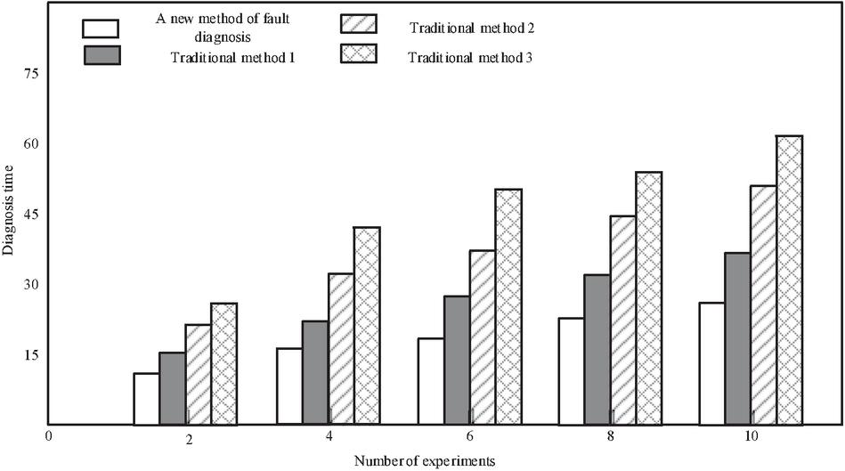
Figure 1 Output speed of diagnosis results.
It can be seen from the image in Figure 1 that the output speed of the new fault diagnosis method is faster, the output time is shorter, and the fastest speed is 11S. The output speed of traditional method 1 and traditional method 3 is the lowest, which shows that both methods are invalid. In this study, the SDG model is used as the evaluation basis of the system operation state, which improves the efficiency of fault diagnosis to a certain extent and improves the use effect of the new fault diagnosis method. The experimental results verify the feasibility of SDG model in fault diagnosis of fluid dynamic control system, and also show that the application of new technology in fault diagnosis of fluid dynamic control system can effectively improve the application effect of diagnosis method. Although the traditional method 2 can complete the fault diagnosis process in a short time, there is still a certain gap compared with the new method. To sum up, the new fault diagnosis method is better than the traditional method.
2.3.3 Analysis of experimental results of fault diagnosis data computation
This part of the experimental results have data characteristics, so it is reflected in the form of data table, the specific content is as Table 3.
Table 3 Calculation amount of fault diagnosis data
| Experimental methods | Maximum amount of data for fault diagnosis/piece | Minimum data calculation for fault diagnosis/piece | Average data calculation of fault diagnosis/piece |
| New fault diagnosis method | 105 | 97 | 100 |
| Traditional method 1 | 145 | 125 | 134 |
| Traditional method 2 | 140 | 135 | 141 |
| Traditional method 3 | 124 | 98 | 117 |
From the analysis of the data in Table 3, it can be seen that in terms of the calculation index of fault diagnosis data, there are great differences between various methods. In the new fault diagnosis method, the amount of data calculation is relatively stable and low, while the traditional method has a large amount of data calculation for the system, and has a certain volatility. According to the experimental results, it can be found that the new fault diagnosis method can reduce the difficulty of data calculation in the process of fault diagnosis to a certain extent, and ensure the operability of fault diagnosis. At the same time, the simple calculation process is also convenient for the promotion of the new fault diagnosis method and reduces the operation difficulty of the staff. Therefore, it can be determined that the application effect of the new fault diagnosis method is better.
In this study, the experimental indicators are set as the accuracy of fault data capture, the output speed of diagnosis results and the amount of fault diagnosis data calculation. Through many experiments, it is determined that the new fault diagnosis method has better effect. In the process of fault diagnosis of speech recognition fluid power control system in the future, a new fault diagnosis method will be used to complete the fault diagnosis process, improve the reliability of fault diagnosis results and ensure the use effect of fluid power control system.
3 Conclusion
Fluid power control system based on English translation speech recognition plays an important role in industrial production. Its normal operation is crucial to the development and transformation of the industry. A new automatic fault diagnosis method of fluid power control system based on English translation speech recognition is proposed. Firstly, the SDG model of fluid power control system is established, and the fault link is obtained and determined. Then the correlation dimension of data in fluid mechanics calculation is analyzed, and the fault data location is realized. On this basis, the fault classification model of the hydraulic power control system is established, and the automatic fault diagnosis of the hydraulic power control system is completed. Finally, the application value of the design method is proved by experiments. Experiments show that the new fault diagnosis method can effectively improve the accuracy and speed of fault data acquisition of fluid power control system, the highest accuracy can reach 89.92%, and the fastest speed is 11S, which can effectively improve the reliability of fault diagnosis results. However, due to the limitation of technology and time, this paper mainly optimizes the faults in the process of data operation, and ignores the shortcomings of other parts. Therefore, in the future research, we need to analyze the shortcomings of other directions in fault diagnosis, and carry out the corresponding optimization design, so as to transform the passive fault diagnosis into active fault diagnosis, and promote the development of fluid power control system.
Acknowledgement
The article is supported by the project named “The Application Research of English Teaching Mode in Higher Vocational Colleges Based on English-Level-Graph and Study-Progression” (Project No.WYJZW-2020-1357) approved by Steering Committee of English Teaching for Higher Vocational Colleges, Ministry of Education of China (Ref. : TEFL 2020 No. 10).
References
[1] Radkevich, E. V., Lukashev, E. A., Vasil’eva, O. A. Hydrodynamic Instabilities and Nonequilibrium Phase Transitions[J]. Doklady Mathematics, 2019, 99(3): 308–312.
[2] Sun, W. J., Jiang, S., Xu, K., et al. Multiscale Simulation for the System of Radiation Hydrodynamics[J]. Journal of Scientific Computing, 2020, 85(2): 1–24.
[3] Tan, W.K. Two-velocity hydrodynamics in fluid mechanics: global existence for 2D case[J]. Nonlinearity, 2021, 34(2): 964–988.
[4] Kambe, T. New perspectives on mass conservation law and waves in fluid mechanics[J]. Fluid Dynamics Research, 2020, 52(3): 031401.
[5] Castillo, Z. J. J., Camarillo, G. K. A., Pérez, S. G. I., et al. Mini-AUV Hydrodynamic Parameters Identification via CFD Simulations and Their Application on Control Performance Evaluation[J]. Sensors, 2021, 21(3): 820–820.
[6] Mittendorf, M., Papanikolaou, A. D. Hydrodynamic hull form optimization of fast catamarans using surrogate models[J]. Ship Technology Research, 2021, 68(1): 14–26.
[7] Jean, R., Ren, F., Zhang, W., et al. Deep reinforcement learning in fluid mechanics: A promising method for both active flow control and shape optimization[J]. Journal of Hydrodynamics, 2020, 32(4–5): 234–246.
[8] Troy, S., Minel, B. A CFD-Based Frequency Response Method Applied in the Determination of Dynamic Coefficients of Hydrodynamic Bearings. Part 1: Theory[J]. Lubricants, 2019, 7(3): 23.
[9] de Silva, C. M., Szydzik, C., Mitchell, A., et al. Experimental fluid dynamics characterization of a novel micropump-mixer.[J]. Biomicrofluidics, 2020, 14(4): 044116–044116.
[10] Tateno, M., Yanagishima, T., Russo, J., et al. Influence of Hydrodynamic Interactions on Colloidal Crystallization.[J]. Physical review letters, 2019, 123(25): 258002.
[11] Yang, Z. H., Wang, S. H., Ma, C., et al. Development of fault diagnosis system for wind power planetary transmission based on labview[J]. The Journal of Engineering, 2019, 2019(23): 9170–9172.
[12] Zhu, H. B., He, Z. M., Wei, J. H., et al. Bearing Fault Feature Extraction and Fault Diagnosis Method Based on Feature Fusion[J]. Sensors, 2021, 21(7): 2524–2524.
[13] Mallikarjuna, P. B., Sreenatha, M., Manjunath, S., et al. Aircraft Gearbox Fault Diagnosis System: An Approach based on Deep Learning Techniques[J]. Journal of Intelligent Systems, 2020, 30(1): 258–272.
[14] Shabbir, N., Kütt, L., Asad, B., et al. Spectrum Analysis for Condition Monitoring and Fault Diagnosis of Ventilation Motor: A Case Study[J]. Energies, 2021, 14(7): 2001–2001.
[15] Lin, M. C., Han, P. Y., Fan, Y. H., et al. Development of Compound Fault Diagnosis System for Gearbox Based on Convolutional Neural Network.[J]. Sensors (Basel, Switzerland), 2020, 20(21): 6169–6169.
[16] Piedad, E. J., Chen, Y. T., Chang, H. C., et al. Frequency Occurrence Plot-Based Convolutional Neural Network for Motor Fault Diagnosis[J]. Electronics, 2020, 9(10): 1711–1711.
[17] Jang, G. B., Cho, S. B. Feature Space Transformation for Fault Diagnosis of Rotating Machinery under Different Working Conditions[J]. Sensors, 2021, 21(4): 1417–1417.
[18] Paolo, C., Mirko, P., Fabio, S., et al. A Vibration Signal-Based Method for Fault Identification and Classification in Hydraulic Axial Piston Pumps[J]. Energies, 2019, 12(5): 953.
[19] Park, J., Park, Y. Experimental Verification of Fault Identification for Overactuated System With a Scaled-Down Electric Vehicle[J]. International Journal of Automotive Technology, 2020, 21(4): 1037–1045.
[20] Hamid, R. K., Wang, Y. Y., Shi, P. Special Issue on ‘SMC based observation, identification, uncertainties compensation and fault detection’[J]. Asian Journal of Control, 2019, 21(1): 1–2.
[21] Wu, L., Wu, L. Research on Business English Translation Framework Based on Speech Recognition and Wireless Communication[J]. Mobile Information Systems, 2021(4): 1–11.
Biography

Jin Zheng has been engaged in English teaching for more than 14 years. She has taught courses such as intensive reading, extensive reading, scientific and technical English translation, and practical writing. In recent years, he has presided over 6 provincial scientific research items, and 5 of which have won the first prize. She has published more than 10 academic papers, edited four textbooks and academic monographs, one set of textbooks was selected into the national eleventh five-year planning textbooks.
International Journal of Fluid Power, Vol. 22_3, 357–372.
doi: 10.13052/ijfp1439-9776.2233
© 2021 River Publishers