Finite Element based Transient Elastohydrodynamic Simulation of Translational Hydraulic Seals
Julian Angerhausen1,*, Hubertus Murrenhoff1, Bo N. J. Persson2, Leonid Dorogin2 and Michele Scaraggi2,3
1Institute for Fluid Power Drives and Systems, RWTH Aachen University, Germany
2Peter Grünberg Institut – 1, FZ Jülich, Jülich, Germany
3Department of Engineering for Innovation, Universitá del Salento, Italy
E-mail: Julian.Angerhausen@ifas.rwth-aachen.de
*Corresponding Author
Received 28 June 2017; Accepted 08 January 2019; Publication 09 April 2019
Seals are crucial machine elements in hydraulic devices. However, especially with regard to dynamic seals – for example in cylinder applications – the physical understanding of the sealing mechanism is still insufficient. In this paper a physically based, transient elastohydrodynamic simulation for translational hydraulic seals is presented. The deformation of the seal is calculated in a dynamic finite element (FE) simulation, hyper- and viscoelastic material properties are taken into account. For the numerical calculation of the fluid film and its influences on the seal deformation the FE simulation is coupled with an implementation of the transient Reynold’s equation. For a physically based calculation of the solid contact, the FE-model is coupled with Persson’s theory of rubber friction and contact mechanics. Both, normal force and solid friction are implemented. In a simulation study the influence of the relative velocity in the contact between the elastic, highly deformable seal and a hard cylinder is investigated. The initial phase of motion is investigated in detail. The simulation results are compared to experimental data of a lubricated sliding contact between an nitrile butadiene rubber (NBR) O-ring and a rough steel surface.
Keywords: Hydraulic seal, sliding friction, lubricated contact, finite element, fluid structure interaction.
Introduction
Seals are crucial machine elements in hydraulic devices. A seal failure can result in expensive production downtimes or even environmentally hazardous leakage. However, while scientific research on elastomeric seals dates back to the 1930s and 1940s [1], especially in regard to dynamic seals – for example in cylinder applications – the physical understanding of the sealing mechanism is still insufficient.
In the practical design and optimisation process of hydraulic seals the deformation of the seal for different system conditions is simulated. Here in general stationary finite element (FE) calculations are performed [2]. Complex dynamic behaviour, especially of the fluid film, is usually neglected. For the simulation of the fluid film often the inverse Reynolds method – or inverse hydrodynamic lubrication (IHL) theory – is applied [3]. Here a stationary contact pressure distribution, computed via FE simulations, is used to calculate the height of the sealing gap. This procedure neglects any solid contact and assumes, that the fluid pressure in the gap is equal to the calculated contact pressure from the FEM. The deformation of the seal, due to (varying) fluid pressures, is neglected. Also often the deformation due to different friction forces is not considered.
Fatu and Hajjam [4] described an IHL based approach with an iteratively calculated coefficient of friction. They first calculated the contact pressure distribution with the FE software ABAQUS, depending on an assumed coefficient of friction. The predicted pressure is then used to compute the fluid film thickness and the resulting coefficient of friction. They show, that the tangential friction, induced by the fluid film, has a noteable influence on the simulation results.
Besides this inverse method, the direct method is commonly used [5]. A methodology that includes the solid (asperity) contact – based on the Greenwood-Williamson contact model [6] – is presented by Salant et al. [7]. Initially a FE simulation is executed in order to calculate a stationary contact pressure. Afterwards, in several iterations, the film thickness is computed in an external program, until the sum of solid and fluid contact pressure equals the sum of the FE calculation. Salant et al. utilised the “influence coefficient method” for the computation of the pressure induced deformation of the seal. The required proportionality factors are obtained from the upstream FE simulation [8]. Bullock et al. [9] applied a similar approach for the simulation of a hydraulic rod seal. Their comparison with experimental data shows, that, when considering mixed friction, the simulation results are in the correct order of magnitude. The direct approach can also effectively be coupled with an online FE simulation and used for practical applications, as e.g. shown by Yang and Salant [10].
Another common approach to include the seal deformation due to hydrodynamic effects is the concept of a viscoelastic half-space. This concept is often used in the field of fundamental research, where complex fluid friction and fluid flow calculations are performed. Here in general geometries of low complexity, for example O-rings or quad-rings, are investigated. The concept allows a very detailed investigation of the lubricated, tribological contact, including the deformation of the contacting surfaces, with an acceptable calculation effort [11]. Complex macroscale deformations, e.g. pressure initiated deformations of a rod seal’s geometry, are neglected.
Wohlers et al. [12, 13] combined the concept of an elastic half-space with an upstream FE calculation in order to implement the direct method. First characteristic diagrams for different system pressures and temperatures are generated. Afterwards the gap distribution is calculated iteratively, based on the stationary Reynolds equation and Persson’s theory of contact mechanics [11, 14]. A comparison of this physically-based approach with experimental data reveals promising results [12].
However, for a full physically based model the nonlinear, frequency dependent material properties have to be considered on a macro- and microscopic scale. Thus the concept of the elastic halfspace in combination with an upstream, static FE simulation is not sufficient but an online, dynamic FE simulation is necessary. Also, in all previously described studies the stationary Reynolds equation was applied for the fluid film calculation. Any transient effects of the fluid were neglected.
A 2-D simulation model of a hydraulic U-cup seal, based on a strongly coupled fluid structure interaction (FSI), is presented by Gao et al. [15]. They consider the transient effects of the fluid and the dynamic effects of the seal’s material. The fluid film calculation is based on the Navier-Stokes equations. Solid friction is neglected and the normal contact conditions are described with the lagrangian multiplier method.
Öngün [16, 17] and Schmidt [18] implemented the fluid film calculations directly into a dynamic FE calculation with the software ABAQUS. While Öngün used the stationary Reynolds equation for the fluid film calculation, Schmidt extended this approach by implementing the transient form of the Reynolds equation. They both use an exponential contact model, where the parametrisation is based on measurements.
In this paper a FEM-based EHD model, based on the concept of Öngün and Schmidt, is presented. The calculation of the fluid film and the implementation of the microscopic contact model into the simulation are described. The results are compared to experimental data for an accelerated motion of a lubricated hard-soft line contact. In this study we consider the simple problem of an NBR O-Ring sliding on a lubricated steel cylinder with a nominal flat surface. Still, the present approach can be easily applied to more complex seal geometries, e.g., lip seals or piston seals.
Simulation Model
In a research cooperation of the Institute for Fluid Power Drives and Controls (IFAS) and the Research Centre in Jülich (FZ-Jülich) a physically based, holistic simulation model for translational hydraulic seals is built. Varying contact forces and complex deformations of the seal, e.g., due to dynamic pressure changes in the hydraulic cylinder, as well as the complex hyper- and viscoelastic behaviour of hydraulic seals are modelled. Their influence on the contact region, and thus on the fluid film (and vice versa), is considered. Thus, the interaction between the microscopic effects in the contact area and the macroscopic, dynamic effects of the seal is considered.
In the tribological system of translational hydraulic seals in general mixed lubrication is assumed, which is the focus of this paper and the presented model. Contributions from both solid and fluid contact have to be considered when describing the system. The structure of a elastohydrodynamic simulation model is shown in Figure 1.
The description of the solid contact and the microscopic effects is physically motivated, based on Persson’s theory of contact mechanics [19, 20]. For the calculation of the fluid film in the mixed lubricated conditions the transient Reynolds equation is applied. Both calculations are combined within the finite element analysis in order to include the transient deformation of the seal in the calculation. Thus, two types of elastomer deformation are considered: On the one hand the macroscopic deformation of the seal in the FE-Model and on the other hand microscopic deformation at the surface asperities in Persson’s contact model.
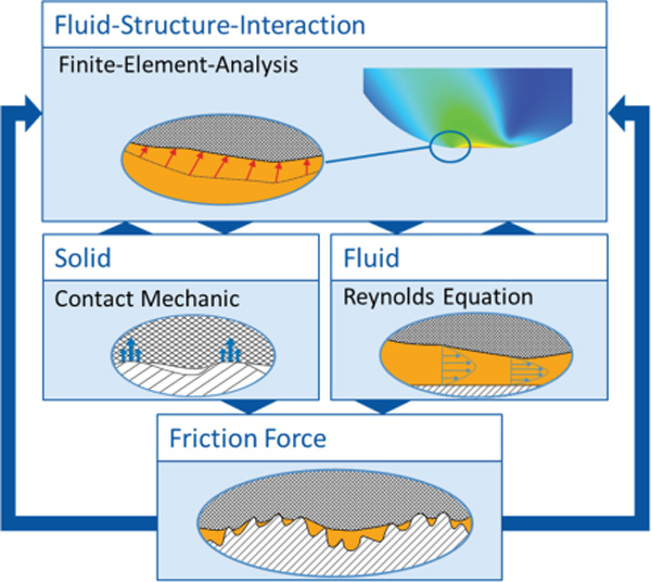
Figure 1 Structure of the elastohydrodynamic simulation.
In Figure 2 the schematic of the investigated contact problem is shown. A rubber cylinder (seal) is squeezed against a hard rough surface (rod) with a normal load FL. The coordinate system is introduced with the x-axis along the sliding direction, where x = 0 mm corresponds to the initial cylinder axis position. The boundary surface is fixed in x-direction.
In the FE-simulation the geometric quantities (separation, velocity), as well as the calculated pressures (fluid and solid contact) are locally-averaged quantities in the area of each node. The real physical quantities vary rapidly in space over many length scales [19].
The normal forces F N and the tangential forces F T act on the seal surface in the contact area. In the mixed friction regime theses forces are the sum of solid contact (Equation 1) and fluid contact forces (Equation 2):
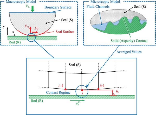
Figure 2 Schematic of the investigated contact.
Where Ai is the corresponding node area (Equation 3):
Where xi is the x-position of node i, as indicated in Figure 2, and w is the contact width of the sealing contact. First, the calculation of the seal’s deformation is presented in the following chapter. Afterwards the calculation and implementation of these forces is described in detail.
Material Deformation
The calculation of the material deformation is based on a FE-simulation model. The hard (steel) contact partner is assumed to be perfectly rigid. The deformation of the soft (NBR rubber seal) contact partner is based on a complex material model provided by ABAQUS [21]. Viscoelastic and hyperelastic effects are considered. A dynamical mechanical analysis (DMA) was performed at FZ Jülich for the seal material that is used in the experiments. For detailed information on the measurement procedure and the generation of a master curve of viscoelastic solids please see [22].
A comparison of the measured strain-stress data and different, commonly used modelling approaches is shown in Figure 3.
The Mooney-Rivlin material model [23] (parameters: D1 = 2.57e-02, C10 = –4.16e-02, C01 = 1.62) is chosen in this study, as it exhibits the closest agreement with the test data. The measured bulk moduli (real and imaginary part) are shown in Figure 4. These curves are implemented in the material model in order to compute the frequency dependent deformations and thus consider viscoelastic effects not only for the microscopic but also for the macroscopic deformations.

Figure 3 Stress–strain curve of the NBR. The measured data is compared to various model approaches.
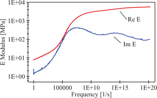
Figure 4 Measured real and imaginary part of the NBR viscoelastic modulus.
Fluid Film
The calculation of the fluid film in the lubricated contact is based on the transient Reynolds equation (Equation 4)
Where the relative velocity v x,rel is defined as the difference of the seal and the rod velocity in x direction. The fluid’s viscosity η is assumed to be constant in this study.
Implementation
For the implementation of the fluid film in the FE calculation, the User Element (UEL) subroutine of ABAQUS is used. This subroutine allows a user based definition of the finite elements’ behaviour. For any UEL the residual vector (RHS) and an array containing the contribution of the UEL to the overall stiffness (Jacobian) matrix of the simulation model have to be defined [21]. A very detailed description of applying this concept in order to implement the Reynolds equation can be taken from Öngün [17] and Schmidt [18]. The fluid film UEL works in the defined contacting zone, between the rod’s and the seal’s surface (Figure 2).
Position and velocity of every node of the seal is provided from the FE model. The gap height h of any node is defined as its distance orthogonal to the (rigid) rod surface. The resulting (fluid pressure and fluid shear) forces are acting on each node in order to implement a fully coupled simulation.
Fluid normal force
For the computation of the fluid based normal force, the fluid pressure , that is acting on the corresponding node area Ai, has to be calculated. The calculation of the fluid pressure (Equation 5) is based on the single pressure gradients at each node (with α = 0.5):
When calculating the pressure derivations (Equation 6) two integration constants arise by reason of integration of the Reynolds equation in regard to x, e.g., h0 when considering only the hydrodynamic pressure:
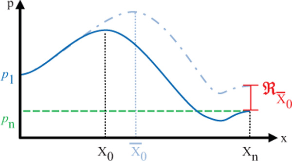
Figure 5 Schematic fluid pressure in the sealing gap with iteration constant x0. A different position leads to a deviation from the boundary condition and thus to a residuum > 0.
This constant h0 corresponds to the height of the sealing gap at the position x0, where the pressure gradient equals zero, with the condition x1 < x0 < xn. As the position x0 is independent of the FE-model, the corresponding height h0 is interpolated, based on the height of the neighbouring nodes. This method proved to be numerically more stable than just choosing the nearest neighbouring node. The position x0, has to be calculated iteratively, such that the boundary condition (Equation 7) is fulfilled, as illustrated in Figure 5. Here node n is located on the outer edge of the seal, thus the pressure pn is assumed to equal atmospheric pressure patm.
The calculation of the position x0 is directly implemented into the ABAQUS Newton-Raphson iteration scheme. Thus, an costly, external iteration loop is not necessary. For this a ghost node n+1 is defined. This node is not connected to the actual FE mesh. It only interacts with the model due to the fluid film calculation. The x-coordinate of the ghost node equals x0. A residual force (Equation 8) acts on the node in x-direction:
Thus, if the residuum equals zero, i.e., the assumption for x0 is correct, the ghost node will remain at its position. On the other hand a residuum not equal to zero will move the ghost node and therefore change the integration constant x0.
Fluid tangential force
Based on the known gap height and the known pressure curve, the tangential (or fluid friction) shear stress can be calculated for every node according to Equation 9:
Stiffness (Jacobian) matrix
For the UEL not only the acting forces, but also the stiffness matrix of the element, i.e., the deviation of the forces in regard to anode’s displacement u, has to be defined, according to Equation 10 [16]:
Validation of the fluid calculations
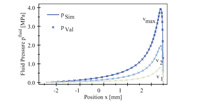
For a validation of the numerical implementation the solution of the numerical model is compared to the analytical solution of the fluid pressure in a journal wedge (Figure 6). The parameters for the calculation are summarised in Table 1.
In the analytical solution stationary conditions are assumed and the deformation of the material is neglected. The pressure at a position x can be calculated using Equation 13 [24]:
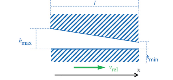
Figure 6 Sketch of the journal wedge.
Table 1 Parameters for the journal wedge
| Journal Wedge | |
|---|---|
| Height hmax | 50 μm |
| Height hmin | 10 μm |
| Vrel,max | 500 mm/s |
| Length l | 5mm |

Figure 7 Fluid pressure as a function of the position in a journal wedge at three different velocities (v1 = 0.1 m/s, v1 = 0.25 m/s, v1 = 0.5 m/s). Comparison of the numerical (Sim) and analytical (Val) solution.
In the calculation the relative velocity is linearly increased up to 0.5 m/s in 1 s. A comparison of the analytical calculation and the ABAQUS simulation are plotted in Figure 7. The pressure is shown for three different velocities during the acceleration process. The numerical model is in a very good agreement with the analytical predictions. Thus, a valid numerical implementation of the Reynolds equation can be assumed.
Solid Contact
While Öngün [17] and Schmidt [18] use a phenomenological function to describe the dependency of solid contact pressure and separation, in the current model a physically based approach is implemented, namely the contact model of Persson which is briefly described in the following section.
The surface of a piston rod has roughness on many different length scales. When the seal is squeezed onto the rod, solid contact occurs at the asperities of the rod’s surface. But at higher magnification non-contact regions become visible at those asperity contact zones, again contact only occurs at the peaks of the surface and small cavities are not completely filled. As the magnification increases the area of contact decreases. This concept is taken into account in Persson’s contact theory by using a diffusion like equation to calculate the normal stress distribution at the interface. The area of real contact can then be deduced from the normal stress distribution.
For the solid contact in the sealing system not only normal but also tangential forces act due to the relative movement between rubber and the rough surface. Those forces lead to oscillating deformations of the rubber and thus to viscoelastic energy dissipation due to internal friction of the rubber. This energy dissipation is one major contribution to the frictional stresses (the other component is adhesion). Every wavelength of the surface profile contributes to the friction force. Bigger wavelength lead to bigger deformations with a lower frequency, while small wavelength lead to small deformations at very high frequencies. Thus contributions from all length scales have to be taken into account in order to calculate the normal stress distribution at the interface, the area of real contact, and the correct solid friction force. Therefore, the concept of power spectral density (PSD) C is applied to describe the surface roughness over several orders of magnitude. For detailed information on the model see e.g. [11, 14, 25].
For the theory the two dimensional PSD is needed, which can be calculated from a measured 1D power spectrum for surfaces with isotropic roughness [26]. The PSD of the surface that is used in the experiments is shown in Figure 8, as a function of the wave number q. The surface was measured in axial and tangential direction [27]. The 1D (C1D) and 2D (C2D) data is shown.

Figure 8 1D and 2D surface roughness power spectra as a function of the wavenumber q; axial direction (dashed line) and the tangential direction (solid line).
The solid blue lines indicate the slope of the corresponding self-affine region of the PSDs; they are depicted shifted from experimental curves for the sake of readability only.
Solid normal force
Based on the PSD and the material data, a physically based correlation of gap height h and the contact pressure psolid can be derived (Figure 9) [26]:
Solid tangential force
The normalised area of real contact  (in relation to the apparent area of contact A0, Equation 18, Figure 9) can be calculated based on the known surface and material data [14]:
The solid tangential stress τcontact only acts in the area of real contact. Therefore, the solid tangential stress is calculated according to Equation 19. For the present model the tangential stress τcontact, which is calculated based on the contact theory of Persson, is assumed to be constant. In reality this parameter is dependent on the relative velocity.

Figure 9 Contact pressure and normalised area of real contact as a function of the separation.
Implementation
For the implementation of the solid contact calculations into the FE simulation, the subroutine for an user interaction (UINTER) is used. This subroutine provides an interface for a complex definition of normal and shear forces between contacting surfaces [21]. As done for the UEL, also for the UINTER not only the forces between the slave and master surfaces at every node, but also the interface stiffness matrix has to be defined. In order to reduce the computational time, the curves for the normal contact pressure and the normalised area of real contact are calculated upstream. The resulting characteristic diagram (Figure 9) is used as an input for the UINTER subroutine. The calculation procedure of the complete simulation model is shown in Figure 10.
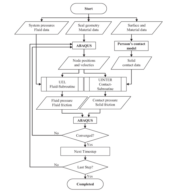
Figure 10 Calculation procedure of the EHL model.
Simulation Results and Comparison with Measurement
The described model is used for an exemplary simulation. The simulation results and a comparison with measurements are reported in this chapter. First, the test rig and the FE mesh are briefly described, afterwards results concerning the influence of the Reynolds equation’s transient term and the influence of the actual relative velocity on the sealing gap are presented.
Experimental Investigation
For the experimental investigation a test rig at the Institute for Fluid Power Drives and Controls (IFAS) was used. A CAD picture of the test rig is shown in Figure 11.
A seal specimen (diameter = 5 mm), located in the specimen holder of the force measurement arm, is brought in contact with a rotating test cylinder (diameter = 200 mm). A detailed description of the test rig can be found in [27], the test conditions are summarised in Table 2.
For a comparison of the simulation with experimental results, the test conditions of the test rig were modelled, as indicated in Figure 11. Effects of the surface topography, which have a distinct influence on the systems behaviour [19, 27], are not considered in this study. Also the idle time has a significant influence on the breakaway force, as shown in [28]. This effect is not considered in the present simulation. Nonetheless, the qualitative dynamical behaviour during the acceleration and deceleration phase can be compared. For the comparison a constant coefficient of solid friction is chosen (μ = 0.8), the actually calculated coefficient of friction is not constant but depends e.g. on the normal force and the relative velocity. The influence of those dependencies is neglected here to emphasise the influence of the transient Reynolds equation and especially the consideration of the actual relative velocity. A detailed investigation revealed, that for low normal forces the load dependency is actually negligible for the investigated system [29].

Figure 11 CAD picture of the test rig. A detailed view of the contact zone and the corresponding FE model are shown on the bottom.
Table 2 Parameters for the experiments
| Test Conditions | |
|---|---|
| Diameter of the O-ring | 5 mm |
| Length of the specimen | 40 mm |
| Material of the O-ring | NBR 70 Shore A |
| Normal load (normal force due to leverage) | 1 kg (31.1 N) |
| Temperature | 20?C(± 1?C) |
| Fluid (viscosity at 20?C) | HLP46 (137 mm2/s) |
Finite Element Model
For the presented analysis the node distance (in the contact zone) in x-direction is 14 μm. In total the model consists of 5750 elements (2D, quad dominated). In the contacting zone a structured mesh is used. The direct implementation of the fluid and solid contact models into the FE software leads to quite short calculation times (e.g., approximately 15 minutes for the following results, computed on a Windows PC with Intel Core i5-3570 CPU @ 3.40 GHz and 16 GB Ram).
Simulated Friction Force and Influence of the Seal’s Deformation
In general the rod’s velocity is used for simulations of the sealing system. However, especially lip seals are extensively elastically deformed in the reversal point, leading to a strong hysteresis [30]. Here the relative velocity in the fluid gap can no longer be assumed to be equal to the rod’s velocity, but it is significantly lower. This behaviour is respected in the transient simulation model, where the relative velocity is defined as follows (Equation 20):
Where is the averaged velocity of all seal nodes in contact with the rod surface.
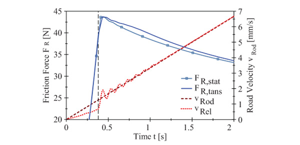
Figure 12 Simulated friction force with and without consideration of the transient fluid film calculation, and the relative and rod velocities as a function of time.
In Figure 12 the simulated friction force is shown. The results of the transient simulation is compared to a stationary model, where actual relative velocity and the transient term of the Reynolds equation are neglected.
In the first phase the seal is elastically deformed and the tangential (friction) force rises. The contacting nodes follow the rods movement with only a minor slip and the relative velocity is significantly lower compared the rod velocity. After about 0.4 s breakaway occurs. The seal slips in opposite direction, the relative velocity rises abruptly. After an oscillation phase the seal stops moving in x-direction and vrel equals the rod’s velocity (t > 1 s). Just after the increase of the relative velocity (dashed line), the transient friction force is slightly lower compared to the calculated stationary force. After breakaway (t > 0.5 s) the influence of the transient term is more distinct. Here, the friction force is higher in the transient simulation. This is due to the consideration of the growing height in the fluid pressure calculation. As the seal rises, the fluid pressure is slightly reduced (see Figure 13 (b)), leading to a higher percentage of solid contact and thus to a higher friction force.
Fluid Pressure and Gap Height
In Figure 13 the calculated fluid pressure build-up and the corresponding seal deformation are illustrated for three different velocities during the acceleration process1. For comparison the solid contact pressure for the stationary calculation is also shown.

Figure 13 Fluid pressure and gap height in the sealing gap. Comparison of transient and stationary calculation for three different velocities.
In the initial phase (a) the influence of the transient calculation is quite distinct. The seal is elastically deformed and moves down on the gap entry side, resulting in a higher fluid pressure – and thus a stronger deformation of the seal. After breakaway (b) the transient fluid pressure is lower, due to the considered influence of the increasing gap height. In the long term (3) the calculated results are equal for both models. Here, the transient effects can be neglected. In the cavitation regime a lower limit (vapour pressure) is implemented in order to avoid negative pressures.
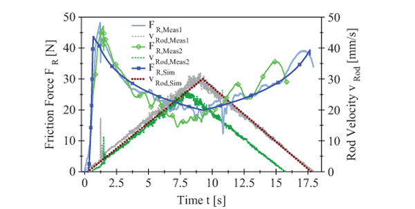
Figure 14 Friction forces and rod velocity as a function of time.
Comparison of Measurement and Simulation
In the experiment the test cylinder was accelerated linearly up to a maximum velocity of about 30 mm/s. Afterwards the cylinder was decelerated to standstill. The cylinder’s motion and the resulting friction force for two individual measurements are shown in Figure 14. The oscillatory behaviour of the measured friction force is induced by a not perfectly uniform surface [27]. Also a comparison with the (transient) simulated results is shown. The simulation is in a very good agreement with the measured curves for both, acceleration and decelerations phase.
Summary and Conclusion
A transient simulation model for translational hydraulic seals is presented. The calculation is based on a FE model. Both, fluid and solid contact are considered by implementing the transient Reynolds equation and the contact theory of Persson. The calculations are physically based and allow the detailed study of non-stationary elastohydrodynamic sliding problems. A comparison of the calculated friction force with experimental results was presented and reveal a good agreement of theory and measurement. For the examined system conditions the influence of the transient term and the deformation of the seal is considerable, especially during the initial phase of motion.
Acknowledgement
The research work was performed within a Reinhart-Koselleck project funded by the Deutsche Forschungsgemeinschaft (DFG). We would like to thank DFG for the project support under the reference German Research Foundation DFG-Grant: MU 1225/36-1 and PE 807/8-1.
Nomenclature
| hrms | Root-mean-square wave height | [m] |
| Ai | Corresponding Area of node i | [m2] |
| E* | Effective elastic modulus | [N/m²] |
| FL | Normal load on the sealing system | [N] |
| Normal force due to fluid contact | [N] | |
| Normal force due to solid contact | [N] | |
| Tangential force due to fluid contact | [N] | |
| Tangential force due to solid contact | [N] | |
| patm | Atmospheric pressure | [MPa] |
| Pressure on node i due to fluid contact | [MPa] | |
| Pressure on node i due to solid contact | [MPa] | |
| vx,rel | Relative velocity in x-direction | [mm/s] |
| vx,Rod | Velocity of the rod in x-direction | [mm/s] |
| vx,Seal | Velocity of the seal in x-direction | [mm/s] |
| Shear stress on node i due to fluid contact | [MPa] | |
| Shear stress on node i due to solid contact | [MPa] | |
| μ | Coefficient of (solid) friction | [-] |
| h | Gap height | [mm] |
| i | Number of a certain FE node | [-] |
| Ki,j | Stiffness matrix | [N/mm] |
| l | Length | [mm] |
| n | Total number of nodes in the contact | [-] |
| p | Pressure | [MPa] |
| Q | Volume flow | [mm³/s] |
| ui | Displacement of node i | [mm] |
| w | Contact width | [mm] |
| xi | x-position of node i | [mm] |
| C(q) | Power spectral density | [m4] |
| Normalized area of real contact | [-] | |
| q | Wave vector | [m–1] |
| α | Parameter for Up-wind scheme | [-] |
| γ | Parameter for asymptotic separation relation | [-] |
| δ | Angle of the journal bearing | [deg] |
| η | Dynamic. viscosity | [Pa s] |
References
[1] G. K. Nikas, “Eighty years of research on hydraulic reciprocating seals,” Proceedings of the Institution of Mechanical Engineers, Part J: Journal of Engineering Tribology, vol. 224, no. 1, p. 1–23, 2010.
[2] F. Kaiser, B. Sauer and S. Eckert, “Development and Validation of a New Method for the Simulation of Starved Conditions of Rod Seals,” 18th International Sealing Conference, 2014.
[3] H. Blok, “Inverse problems in hydrodynamic lubrication and design directives for lubricated flexible surfaces,” Proceedings of the International Symposium on Lubrication and Wear, D. Muster and B. Sternlicht eds, Houston, USA, p. 1–151, 1963.
[4] A. Fatu and M. Hajjam, “Numerical modelling of hydraulic seals by inverse lubrication theory,” Proceedings of the Institution of Mechanical Engineers, Part J: Journal of Engineering Tribology, vol. 225, no. 12, p. 1159–1173, 2011.
[5] G. K. Nikas, “Elastohydrodynamics and Mechanics of Rectangular Elastomeric Seals for Reciprocating Piston Rods,” Journal of Tribology, vol. 125, no. 1, p. 60, 2003.
[6] J. A. Greenwood and Williamson, J. B. P., “Contact of Nominally Flat Surfaces,” Proceedings of the Royal Society A: Mathematical, Physical and Engineering Sciences, vol. 295, no. 1442, p. 300–319, 1966.
[7] R. F. Salant, N. Maser and B. Yang, “Numerical Model of a Reciprocating Hydraulic Rod Seal,” Journal of Tribology, vol. 129, no. 1, p. 91, 2007.
[8] X. Jia, S. Jung, W. Haas and R. F. Salant, “Numerical simulation and experimental study of shaft pumping by plunge ground shafts with rotary lip seals,” Tribology International, vol. 48, p. 155–161, 2012.
[9] A. K. Bullock, D. G. Tilley, D. N. Johnston, C. R. Bowen and P. S. Keogh, “Non-linear friction in reciprocating hydraulic rod seals: Simulation and measurement,” Journal of Physics: Conference Series, vol. 181, p. 012009, 2009.
[10] B. Yang and R. F. Salant, “Elastohydrodynamic lubrication simulation of O-ring and U-cup hydraulic seals,” Proceedings of the Institution of Mechanical Engineers, Part J: Journal of Engineering Tribology, vol. 225, no. 7, p. 603–610, 2011.
[11] M. Scaraggi and Persson, B. N. J., “General contact mechanics theory for randomly rough surfaces with application to rubber friction,” The Journal of chemical physics, vol. 143, no. 22, p. 224111, 2015.
[12] A. N. Wohlers, O. Heipl, B. Persson, M. Scaraggi and H. Murrenhoff, “Numerical and Experimental Investigation on o-ring seals,” International Journal of Fluid Power, 2009.
[13] A. N. Wohlers, O. Heipl and H. Murrenhoff, “Computational Study of the Influence of Roughness on the Friction Behaviour of Step Seals,” Proceedings : 6th FPNI – PhD Symposium West Lafayette 2010; West Lafayette, Indiana, USA, June, 15 – 19, 2010; an initiative of Fluid Power Net International / Ed. Monika Ivantysynova. – Vol. 1, p. 363–372, 2010.
[14] Persson, B. N. J., “Theory of rubber friction and contact mechanics,” The Journal of Chemical Physics, vol. 115, no. 8, p. 3840, 2001.
[15] H. Gao, B. Li, X. Fu and G. Yang, “A Strongly Coupled Fluid Structure Interaction Solution for Transient Soft Elastohydrodynamic Lubrication Problems in Reciprocating Rod Seals Based on a Combined Moving Mesh Method,” Journal of Tribology, vol. 137, no. 4, 2015.
[16] Y. Öngün, M. Andre, D. Bartel and L. Deters, “An axisymmetric hydrodynamic interface element for finite-element computations of mixed lubrication in rubber seals,” Proceedings of the Institution of Mechanical Engineers Part J-Journal of Engineering Tribology, vol. 222, no. J3, p. 471–481, 2008.
[17] Y. Öngün, “Finite element simulation of mixed lubrication of highly deformable elastomeric seals”, Vols. Bd. 2010, 4, Aachen: Shaker, 2010, p. 93 S.
[18] T. Schmidt, “Mischreibung und Verschleiß in Hydraulikdichtsystemen”, Hannover: Gottfried Wilhelm Leibniz Universität, 01.01.2011, pp. X, 175.
[19] M. Scaraggi, J. Angerhausen, L. Dorogin, H. Murrenhoff and B. Persson, “Influence of anisotropic surface roughness on lubricated rubber friction with application to hydraulic seals,” Wear, 2017.
[20] M. Scaraggi, L. Dorogin, J. Angerhausen, H. Murrenhoff and B. Persson, “Elastohydrodynamics for Soft Solids with Surface Roughness: Transient Effects,” Tribology Letters, pp. doi:10.1007/s11249-017-0878-9, 2017.
[21] Dassault Systémes, ABAQUS (2016) ABAQUS Documentation, RI, USA, 2016.
[22] B. Lorenz, W. Pyckhout-Hintzen and B. Persson, “Master curve of viscoelastic solid: Using causality to determine the optimal shifting procedure, and to test the accuracy of measured data,” Polymer, vol. 55, no. 2, pp. 565–571, 2014.
[23] R. S. Rivlin, “Large elastic Deformations of isotropic materials VII”, Vols. No 865, Vol. 243, pp. 251 – 298, London, 1951.
[24] G. Jacobs and M. Plogmann,“Tribologie”, 3. Aufl., Ausg. 10/2012 ed., Aachen: Mainz, 2012,
[25] M. Scaraggi and B. N. J. Persson, “Friction and universal contact area law for randomly rough viscoelastic contacts,” Journal of Physics: Condensed Matter, vol. 27, 2015.
[26] B. Persson, “Relation between Interfacial Separation and Load: A General Theory of Contact Mechanics”, Physical Review Letters, vol. 99, no. 12, 2007.
[27] J. Angerhausen, H. Murrenhoff, L. Dorogin, M. Scaraggi, B. Lorenz and Persson, B. N. J., “Influence of anisotropic surfaces on the friction behaviour of hydraulic seals,” Proceeding of the 2016 Bath/ASME Symposium on Fluid Power and Motion Control, 2016.
[28] J. Angerhausen and H. Murrenhoff, “Influence of anisotropic surfaces on the friction behaviour in hard/soft line contacts,” 19th International Sealing Conference, 2016.
[29] J. Angerhausen, H. Murrenhoff, L. Dorogin, M. Scaraggi and B. N. J. Persson, “Influence of transient effects on the behaviour of translational hy-draulic seals”, The 11th International Fluid Power Conference, 11. IFK, 19.-21.3.2018, Aachen, 2018.
[30] O. P. Heipl, “Experimentelle und numerische Modellbildung zur Bestimmung der Reibkraft translatorischer Dichtungen”, vol. 72, Aachen: Hochschulbibliothek der Rheinisch-Westfälischen Technischen Hochschule Aachen, 2013.
Biographies

Julian Angerhausen Born in 1988 in Krefeld, Germany. Studied mechanical engineering and economics at RWTH Aachen University. Since October 2014 he is member of the scientific staff at the Institute for Fluid Power Drives and Controls (IFAS) at RWTH Aachen University. His research focuses on the transient behaviour of translational hydraulic seals.

Hubertus Murrenhoff Born in 1953 he is the director of the Institute for Fluid Power Drives and Controls (IFAS) at RWTH Aachen University, Germany. Main research interests cover hydraulics and pneumatics including components, systems, controls, simulation programs and the applications of fluid power in mobile and stationary equipment.

Bo N. J. Persson Born in 1952 he is research scientist at FZ-Juelich and CEO at MultiscaleConsulting. Main interest at present is all aspects of tribology, e.g., friction, adhesion and contact mechanics.

Leonid Dorogin Born in St.-Petersburg, Russia in 1984, and graduated from University of Tartu in Estonia. Currently researcher at FZ Juelich, Germany. Main interests in adhesion, tribology, nanomechanics and theory of defects.

Michele Scaraggi Born in 1982 he is assistant professor in applied mechanics at University of Salento, Italy. Main research interests cover contact mechanics and tribology, surface physics, bio-mimetics, multibody and computational mechanics, mechanical design.
International Journal of Fluid Power, Vol. 20 1, 1–26.
doi: 10.13052/ijfp1439-9776.2011
© 2019 River Publishers
1An animation of the presented results is available at: http://www.ifas.rwth-aachen.de/html/02_science/showProject.php?id=kos&lang=en