A Review of Electro-Hydraulic Servovalve Research and Development
Paolo Tamburrano1,2,*, Andrew R. Plummer2, Elia Distaso1, and Riccardo Amirante1
1Department of Mechanics, Mathematics and Management (DMMM)–Polytechnic University of Bari, Via Orabona 4, 70125, Bari, Italy
2Centre for power transmission and motion control (PTMC), Department of Mechanical Engineering, University of Bath, Claverton Down BA2 7AY, Bath, UK
E-mail: paolo.tamburrano@poliba.it; p.tamburrano@bath.ac.uk
*Corresponding Author
Received 11 April 2018; Accepted 08 October 2018; Publication 12 April 2019
Abstract
This paper provides a review of the state of the art of electro-hydraulic servovalves, which are widely used valves in industrial applications and aerospace, being key components for closed loop electrohydraulic motion control systems. The paper discusses their operating principles and the analytical models used to study these valves. Commercially available units are also analysed in detail, reporting the performance levels achieved by current servovalves in addition to discussing their advantages and drawbacks. A detailed analysis of research that investigates these valves via computational fluid dynamic analysis is also provided. Research studies on novel control systems and novel configurations based on the use of smart materials, which aim to improve performance or reduce cost, are also analysed in detail.
Keywords: Review, servovalve, control, piezoelectric actuator.
Introduction
Electro-hydraulic servovalves are widely used components in the aerospace and industrial sectors because of their reliability and high performance levels (Plummer, 2016). A servovalve has the capability of providing a continuous variation of flow according to an input signal by using a sliding spool as the control element (Hunt & Vaughan, 1996). It constitutes a key component for closed loop electrohydraulic motion control systems (Plummer, 2016, Merritt, 1967).
Originally, electro-hydraulic valves were conceived for the military sector during World War II, and subsequently used in applications such as radar drives, guidance platform drives and missile launcher controls (Maskrey and Thayer, 1978). The initial designs were based on the single-stage proportional actuation achieved through proportional solenoids. The first two-stage servovalve was patented by Tinsley Industrial Instruments Ltd only after the end of World War II, in 1949 (Tinsley, 1949); in this configuration, a small sliding spool was used as a pilot stage (to be also referred to as first stage) to create a differential pressure across a vane actuator driving a rotary valve main stage (to be also referred to as second stage). This novel architecture allowed higher forces to be achieved compared to conventional single-stage valves. This design was further improved by using mechanical feedback between the pilot stage and the main stage (Boyar et al., 1955).
A major improvement was achieved when torque motors were implemented in place of proportional solenoids, in addition to the introduction of electrical feedback between the pilot stage and the main stage (Blackburn et al., 1960). As far as the pilot stage is concerned, a novel concept was developed by Moog in 1953 (Moog, 1953): a single flapper nozzle pilot stage was conceived; it was composed of a fixed orifice and a nozzle with variable orifice controlled by a flapper moved by a torque motor. In such a way, the pressure was changed on one of the spool ends, with the other end being in contact with a spring. Moreover, a tension spring was used to connect the torque motor with the main stage spool, thus achieving a very effective mechanical closed loop control (Carson, 1960).
Subsequently, the pilot stage was improved by substituting a single nozzle-flapper with a double nozzle-flapper, which resulted in a better control of the null offset (Moog, 1965). This design was further improved by devising systems able to separate the torque motor from the hydraulic fluid (Wolpin, 1965). This avoided a common fault which was due to magnetic particles carried in the oil and accumulating in torque motors. Moreover, an additional improvement consisted of supporting the torque motor on a flexure providing a lightweight frictionless pivot which much reduced valve threshold, namely the input deadband (Plummer, 2016).
Such improvements led to double nozzle-flapper first stages becoming more widespread than spool first stages, because nozzle-flapper arrangements were cheaper to manufacture than spool first stages, in addition to the fact that all spool first stages required dither to overcome friction. As an alternative to the double nozzle-flapper valve, a jet valve type was developed by Atchley (1959); the pilot stage consisted of a pipe providing oil flow to two receivers hydraulically connected to the main stage spool. The rotation of the pipe caused differential pressure to be created at the spool ends, thus moving it proportionally to the input signal.
The advent of these designs and their further development (discussed in the following) has allowed servovalves to be used in a wide variety of areas in the past six decades. Several applications include primary and secondary flight control, flight simulators, industrial automation, controls for industrial robots, turbine controls, and materials testing machines.
Due to their importance and wide-spread usage, this paper discusses the state of the art of electro-hydraulic servovalves. Their operating principles and mathematical models will be introduced. An overview of commercially available servovalves will also be given, indicating the performance levels achieved by current servovalve models. A detailed review of the current research that is focused both on the fluid dynamic analysis and on novel control systems of servovalves will be provided. Also, current investigations aimed at developing novel designs for servovalves, based on smart materials, will be discussed in detail.
Servovalves: Operating Principles and Analytical Models
Like a proportional valve, a servovalve has the task of providing a continuous variation of flow rate as a function of an input signal. This characteristic is achieved by providing the servovalve with a sliding spool moving inside a bushing sleeve having rectangular holes (slots) or annular grooves machined on its surface to achieve a precise flow rate trend versus spool position (Parr, 2011). One difference between a servovalve and a proportional valve is the spool overlap in the center position. The spool overlap in servovalves is usually very small, often 1% of the spool stroke or less (Amirante et al., 2014a), while larger overlaps (greater than 5% of the spool stroke) are usually present in proportional valves. The larger overlap gives a significant non-linearity reducing control accuracy, but allows proportional valves to be manufactured with larger tolerances and hence without a separate bushing. A comprehensive review of direct drive proportional electrohydraulic spool valves is provided in (Tamburrano et al., 2019).
A servovalve is usually composed of a main stage (also called second stage) housing the main spool used for metering flow (four-way spool valves are extensively used) and a pilot stage (also called first stage) serving asa hydraulic amplification system, thus forming a two stage configuration. Three and four stage servovalves also exist for controlling larger flows, incorporating one or two larger spools (respectively). Although servovalves are usually provided with filters, erosion of the metering edges may occur over long periods of operation because of particle contamination (Hunt and Vaughan, 1996). The effects of degradation and life prediction under erosive wear were thoroughly described in (Zhang et al., 2014). A series of physics of failure (PoF) models for particle erosion wear of electrohydraulic servovalves were established in (Fang et al., 2013).
The hydraulic amplification system creates a pressure difference across the main spool end faces which is capable of moving the spool. The force developed is very high compared to a proportional valve using proportional solenoids to directly drive the spool, which results in a much faster response. The hydraulic amplification system, referred to as the first stage or the pilot stage, usually employs a torque motor, which requires low electrical input power, up to 1 or 2 W, with a required current of less than 0.2 A (Hunt and Vaughan, 1996). The electrical input power is amplified in the first stage to at least 10W of hydraulic power, and then converted by the main spool to controlling around 10kW of hydraulic output power, thus achieving very large power magnification, with power gains of the order of 104 to 106 (Plummer, 2016, Maskrey and Thayer, 1978). A torque motor is a small electromagnetic actuator mainly composed of coils, pole pieces, and an armature. In the most common type of servovalve, a nozzle-flapper valve, the armature is connected to the flapper. A non-magnetic flexure tube is used to support the flapper while separating the torque motor from the hydraulic fluid.
There can be either an electrical feedback or a mechanical one, the latter being achieved by means of a feedback spring connecting the spool with the moving flapper. The feedback spring is usually connected to the main spool by means of a ball on its end (Hunt and Vaughan, 1996). Small internal mechanical movements in the torque motors can occur, thus causing changes in the nominal zero position of a servovalve, called null shift (Hunt and Vaughan, 1996). A few methods, acting either on the torque motor or on the main spool, are used to adjust the null shift.
With reference to a double nozzle-flapper valve (see Figure 1), the pressure difference necessary to move the main stage spool is achieved through a hydraulic bridge composed of two fixed orifices and two nozzles having variable flow areas, which can be varied by changing the flapper position (the flapper stroke can be up to about 0.1 mm). When the coils of the torque motor are excited, the generated magnetic field makes the flapper assembly rotate from the central position towards one of the two nozzles according to the input current; the different flow areas through the two nozzles cause a pressure difference across the end faces of the main spool, which can move from its initial position. When the spool moves, it drags the feedback spring, which in turn creates a restoring torque on the flapper assembly. The spool continues moving until the restoring torque equals the torque exerted by the torque motor.
An alternative to the nozzle-flapper design of pilot stage is the jet pipe, which is shown in Figure 2a. In this case, the torque motor bends a pipe from which a high pressure jet is directed towards two fixed receivers, which are hydraulically connected to the main spool end faces. When the pipe is in a centred position, the jet is equally split between the two receivers, thus maintaining an equal pressure at the spool end faces. Instead, the rotation of the pipe causes a pressure difference at the end faces of the spool, which is then forced to move from its initial position. The jet-pipe valve is more reliable than the double nozzle-flapper valve as far as the failure mode is concerned; in fact, because the pipe nozzle diameter is smaller than the receiver diameter, a possible blockage because of particle contamination would occur in the pipe nozzle. This would cause the main spool to remain in its rest position, thus achieving a safe failure mode. In contrast, the blockage of either nozzle in a double-nozzle valve would cause the main stage spool to move to full stroke.
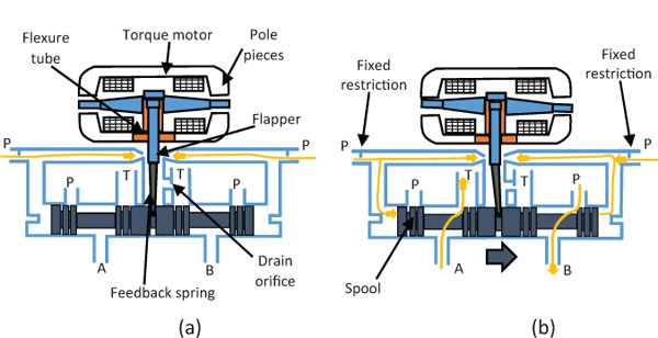
Figure 1 Operating principle of a double nozzle-flapper servovalve with mechanical feedback: (a) null position, (b) fluid modulation.
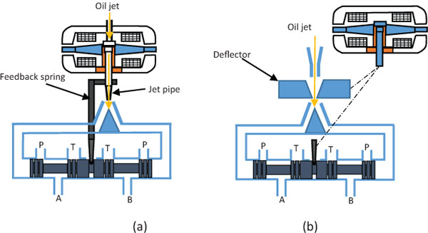
Figure 2 Operating principle of a jet pipe (a) and deflector jet (b) both with mechanical feedback.
A similar operating principle is obtained with the deflector jet valve (shown in Figure 2b): in this case, the moving part is the deflector, which is actuated linearly by the torque motor.
All the pilot stages analysed so far pass a small continuous flow rate, even with no coil current. Despite being small compared to the flow rate through the main stage, such a quiescent flow (referred to as internal tare leakage) represents a non-negligible power loss, which is still an unsolved problem.
Several studies have been proposed to model servovalves, using analytical, CFD (Computational Fluid Dynamics) and/or FEM (Finite Element Method) approaches (Lin and Akers, 1989, Hiremath, 2013, Urata et al., 2008, Ghasemi et al., 2008, Di Rito and Galatolo, 2008, El-Araby et al., 2011, Gordić et al., 2004, Maré and Attar, 2008, Hiremath and Singaperumal, 2010). In this section, analytical models are considered. The torque produced by the torque motor can be expressed as a function of the current intensity i and the angular position θ:
where the values of coefficients Kt and Km depend on the connection of coils, and are obtained experimentally. Kt is defined as the torque constant of the torque motor, while Km the magnetic spring constant of the torque motor (Merritt, 1967). Analytical models are also available in the literature to calculate Kt and Km (see, e.g., Gordić et al. 2004).
With reference to Figure 3, assuming that the main spool (having mass M) moves with a displacement denoted by X, the following equations can be applied to analytically study the main stage valve (Gordić et al., 2004, Persson et al., 2016, Li et al., 2018). The overall actuation force acting on the main spool is to be calculated as the product of the pressure difference between the left and right control chambers (pl – pr ) and the spool area A. This force is counteracted by the spool flow forces (Fflow), the elastic force of the feedback element (Fel), the inertia force () and the damping force ()(Gordić et al. 2008):
The flow forces are usually very high and affect the spool dynamics. Geometric modifications to spool valves are made in the scientific literature to reduce the flow forces (Amirante et al., 2014b, Amirante et al., 2016). The flow rates qs,r and qs,l, flowing from the pilot stage into the chambers at either end of the main spool are calculated as follows (Persson et al., 2015):
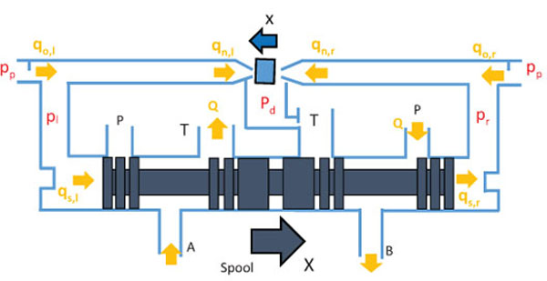
Figure 3 Schematization of the main stage spool connected with a double nozzle-flapper pilot stage.
where E is the bulk modulus, vvol,l and vvol,r are the volumes in the left and right chambers at the spool extremities, and cs is the cross spool leakage coefficient. The flow rate Q flowing through a metering chamber of the main spool can be calculated as:
where CD is the discharge coefficient in the metering chamber, B is the slot width, ρ is the oil density, and Δp is the pressure drop through the metering section (Persson et al., 2015).
Equations 1 to 5 can be applied to the second stage of any servovalve, regardless of the amplification system adopted. From the analysis of Equations (1) to (4), it can be seen that the operating pressures of the hydraulic system have a great influence upon the actuation force of the main spool and, therefore, upon the response time of the valve. Moreover, Equation (5) reveals that, for a given value of the pressure drop through the metering section and assuming a constant value for the discharge coefficient, the flow rate through the main stage spool is proportional to the spool displacement. Alternatively, maintaining the spool in a fixed position X and assuming a constant value for the discharge coefficient, the flow rate increases with the square root of the pressure change.
With regard to the first stage of a flapper nozzle valve (see Figure 3), the flow rate through the fixed orifices can be calculated as follows:
where suffix o denotes either of the two fixed orifices, respectively, and d denotes the orifice diameter. The flow rate through the variable nozzles can be calculated as follows (see Figure 3):
where suffix n denotes either of the two nozzles; x and xin are the displacement and clearance of the flapper, respectively. Finally, the following equations are to be fulfilled for the continuity of flow:
The torque exerted by the torque motor (see Equation 1) must be able to counteract the flow force acting on the flapper, Fflow,fl; this can be estimated as the difference between the flow force acting on the left and right side flapper, as demonstrated in (Li et al., 2018):
The above-listed equations are used to model servovalves for valve sizing, to determine the required valve flow rate and frequency response (Moog, 2017), and to evaluate the effects of the valve geometry upon the valve performance, such as the influence of orifice sizes (Mcnea and Duan, 2013); they can also be used for optimization of the valve geometry to improve the valve performance.
Commercially-Available Valves
Commercially available servovalves rely on large actuation forces, obtained through hydraulic amplification systems analysed in the previous section (i.e., nozzle flapper, jet pipe, deflector jet), to optimise the response speed; the capability to produce a large actuation force, called chip shear force, is also important to avoid jammed spool conditions because of particle contamination. Large actuation forces are capable of shearing a chip if it is jammed between the metering edges. This feature makes servovalves particularly suited to aerospace applications, where it is essential to avoid valve failure (Plummer, 2016).
The small spool overlaps, in addition to the high actuation forces and the absence of heavy moving parts, make commercially available servovalves respond more quickly than proportional valves. To achieve very small overlaps, servovalve spools are precision made and coupled with bushing sleeves: the bushing is manufactured as accurately as feasible and the spool is then matched to an individual bushing (see Figure 4), contrary to proportional valves which usually have the spool sliding directly inside a cast iron valve housing. In addition, the spool of a servovalve usually does not have grooves or notches, but rectangular holes (slots) or annular grooves are cut directly on the bushing surface to achieve flow metering.
Two stage valves can provide maximum flow rates up to 200 l/min for a pressure drop through the valve of 300 bar (Moog, 2017). Depending on the type of applications, either mechanical feedback or electrical feedback can be used. The former is more suited to aerospace applications where weight and reliability are most important, the latter to industrial applications. Industrial valves need to be cheaper with low maintenance, including: larger bodies for easier machining, separate first stage for easier adjustment and repair, standardised port patterns, better in-built filtering to handle the lower industrial filtration standards (Plummer, 2016).

Figure 4 Example of spool and bushing sleeve for servovalves (Moog 2017).
Table 1 Characteristics of type 30 Moog double nozzle-flapper valve (Moog 2017)
| Valve Weight (kg) | Max Flow at 210 bar (l/min) | Actuation Force at 210 bar (N) | Response Time at 210 bar (ms) to Reach 90 % of the Opening | Tare Leakage at 210 bar (l/min) | |
|---|---|---|---|---|---|
| Series 30 | 0.19 | 12 | 245 | 2.5 | <0.35 |
| Series 31 | 0.37 | 26 | 245 | 2.5 | <0.45 |
| Series 32 | 0.37 | 54 | 490 | 4.5 | <0.50 |
| Series 34 | 0.50 | 73 | 620 | 7 | <0.60 |
| Series 35 | 0.97 | 170 | 710 | 12 | <0.75 |
Table 1 reports some characteristics for a commercially available two-stage double nozzle-flapper valve with mechanical feedback realized by one manufacturer (Moog 2017). This type of valve is divided into 5 series according to the size of the valve. It is noteworthy that the weight of the valve increases with the size, but the maximum weight is only about 1 kg, thus highlighting that these valves are compact and light compared to proportional valves. Also the actuation force increases with the size of the valve, because of the larger main spool diameters. The values of the actuation force are up to 700 N, thus being notably higher than those obtained with direct drive valves. The internal tare leakage ranges from 0.35 to 0.75 l/min depending on the size of the valve. Also the response times are affected by the size of the valve, with values ranging from 2.5 ms to 12 ms to reach 90 % of the opening.
Similarly, Table 2 reports the specifications for a deflector jet valve with mechanical feedback realized by the same manufacturer (Moog, 2017). Also this valve is divided into 5 series depending on the size of the valve. The characteristics in terms of weight and response times are very similar to the double nozzle-flapper valve for equal values of the flow rate. In terms of actuation forces, the deflector jet valve allows higher values to be achieved.
Figures 5 and 6 show the frequency response Bode plots of the same valves achieved for a supply pressure of 210 bar and 50% of the maximum input current amplitude. The graphs reveal that, for these operating conditions, the –90◦ phase lag frequency for the nozzle-flapper valve varies from around 90 Hz to around 250 Hz, the highest values being obtained for the smallest sizes. In the case of the deflector jet valve, the –90◦ phase lag frequency varies from about 50 Hz to about 250 Hz; also in this case, the smaller the size of the valve, the higher the –90◦ phase lag frequency.
Table 2 Characteristics of type 30 Moog deflector jet valve (Moog 2017)
| Valve Weight (kg) | Max Flow at 210 bar (l/min) | Actuation Force at 210 bar (N) | Response Time at 210 bar (ms) to Reach 90 % of the Opening | Tare Leakage at 210 bar (l/min) | |
|---|---|---|---|---|---|
| Series 260 | 0.31 | 12 | 245 | 2.5 | <0.45 |
| Series 261 | 0.35 | 29 | 489 | 5 | <0.45 |
| Series 262 | 0.39 | 54 | 489 | 5 | <0.45 |
| Series 264 | 0.45 | 73 | 712 | 7.5 | <0.45 |
| Series 265 | 0.78 | 170 | 1112 | 13.5 | <0.75 |

Figure 5 Normalised flowrate over input current Bode Plot for type 30 Moog double nozzle-flapper servovalve for supply pressure of 210 bar and 50% of the maximum input amplitude (Moog, 2017).
In addition to two-stage servovalves, direct drive servovalves are also constructed by manufacturers. The actuation is achieved through linear force motors; direct current flows in a coil producing an interaction with a magnetic field generated by rare earth magnets. Force motors have lower moving mass and larger driving forces than proportional solenoids and are more linear, and thus have better performance as far as response speed and chip shear force are concerned. The maximum force exerted by a linear motor is of the order of 200 N (Moog, 2017).
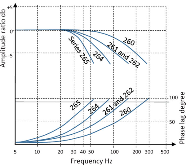
Figure 6 Normalised flowrate over input current Bode Plot for type 26 Moog deflector jet servovalve for supply pressure of 210 bar and 50% of the maximum input amplitude (Moog, 2017).
Figure 7 shows a permanent magnet linear force motor directly driven valve manufactured by Moog (D633 type). For this model, the maximum flow rate is about 70 l/min at 350 bar, the response time for 0 to 100% stroke is about 15 ms. The maximum power consumption is 28.8 W (with 1.2 A at 24 V DC); the mass is 2.5 kg.
Table 3 qualitatively summarises the different characteristics among commercially available single stage proportional valves, linear force motor directly driven valves, and two-stage servovalves, adapted from (Plummer, 2016).
Fluid-dynamic Research
A detailed analytical model was developed in (Li, 2016) to study the fluid flow within jet-pipe and deflector jet valves. The analytical model is capable of taking into account the structural parameters, the distance between the jet-nozzle exit and the receiving surface, the angles between the two receiver holes and the distance between the two receiver holes. The analytical model was validated by 3D CFD simulations achieved in Ansys Fluent through unstructured meshes, and also supported by experimental data. Figure 8 reports the contours of pressure achieved for a pipe displacement of 0 mm, 0.05 mm and 0.1 mm. It is visible from the contours of pressure that the differential pressure on the two receivers increases with the pipe displacement.

Figure 7 Permanent magnet linear force motor directly driven valve (D633 by Moog).
Table 3 Characteristics of different types of electro-valves
| Direct Actuated Proportional Valves (Open Loop) | Direct Actuated Proportional Valves (Electrical Feedback) | Force motor DDV (electrical feedback) | Two-stage ervovalve, mechanical feedback | Two-stage servovalve, electrical feedback | |
|---|---|---|---|---|---|
| Actuation | |||||
| forces | Low | Low | Medium | Very high | Very high |
| Hysteresis | High | Medium | Low | Low | Very low |
| Frequency | |||||
| response | Very low | Low | Medium | High | Very high |
| Cost | Very low | Low | Medium | High | Very high |
| Size | Large | Very large | Very large | Small | Medium |
In (Pan et al., 2011) the simulation of the discharge characteristics of the main stage spool of a servovalve was performed, and a general orifice flow mathematical model was developed under the conditions of laminar and turbulent flow. Partial 3D grids were generated for 22 orifice opening sizes; the inlet pressure was considered equal to 100 bar. It was demonstrated that, for a fixed position and geometry, the discharge coefficient increases with the Reynolds number in the laminar region until reaching a constant, asymptotic value for fully turbulent flow. Based on the simulation results, an analytical formula for the discharge coefficient, valid in laminar, transitional and turbulent conditions, was derived and validated.

Figure 8 Contours of pressure predicted for a jet-pipe displacement of 0 mm, 0.05 mm and 0.1 mm (Li 2016).
To date CFD investigations presented in the literature have mainly been focused on nozzle-flapper valves. In (Jacob et al., 2011), a CFD analysis was performed to study the flow field in the pilot stage of a double nozzle-flapper valve; the fluid was treated as incompressible and the standard k-ɛ model was used to model the turbulence. That work showed the reliability of the standard k-ɛ model for the fluid prediction in the pilot stage of a double nozzle–flapper. In (Li et al., 2013), experimental and numerical investigations were carried out to study the cavitation phenomenon occurring in the fluid zone comprised between the flapper and the nozzle. The study of cavitation in nozzle-flapper valves can play an important role in the design of these valves, as cavitation can promote surface damage, vibration and noise. The 3D model along with the CFD mesh employed in (Li et al., 2013) are reported in Figure 9. The mesh consisted of about 400000 elements. The multiphase mixture flow model coupled with the cavitation model developed by Singhal et al. (YE et al., 2010) was utilized, since it accounts for the effect of non-condensable gases, which can significantly affect the cavitation intensity. The standard k–ɛ model was used to solve turbulence. In parallel to CFD investigations, experimental data were retrieved using the experimental circuit shown in Figure 10: to visualize the flow phenomenon, a high speed video camera was used. The investigation was carried out at several Reynolds numbers.
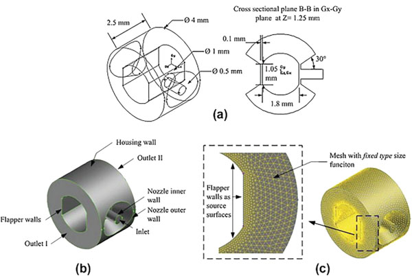
Figure 9 Flapper–nozzle assembly simulated in (Li et al. 2013): (a) Geometry model; (b) Boundary conditions; and (c) Computational grid.
The following conclusions were drawn. As shown in Figure 11, in a nozzle-flapper assembly, the flow impinges perpendicularly (x direction) on both surfaces of the flapper; subsequently, radial jets are formed which in turn impinge on the housing wall. After impinging on the housing wall, the radial jet flows reattach to the flapper surface forming vortexes in the annulus between the housing wall and the flapper surface. The nozzle tips and flapper curved edge are the main sources of cavitation locations. The nozzle tip hosts the first location for cavitation. Then, cavitation bubbles propagate downstream following the radial wall of the jet flow formed in the flapper-nozzle slot. The downstream curved edge of the flapper edge is the other source of cavitation in that it accelerates the flow, causing a dramatic pressure drop that leads to significant cavitation.
A numerical and experimental analysis was performed in (Aung et al., 2014) to have a better understanding of the flow forces and energy losses in a nozzle-flapper assembly. Because of the behaviour illustrated in Figure 11, the flapper is subjected, in addition to the main flow force acting perpendicularly, to four additional lateral components of the flow forces due to the impact of flow reattachment. These lateral forces are not usually in equilibrium because of geometric imperfections, which make the flow structure not perfectly symmetric. Five different flapper–nozzle structures with three different null clearances of 0.1 mm, 0.05 mm and 0.033 mm were considered in their analysis. Seven different flow conditions varying nozzle inlet pressures from 10 bar to 70 bar were taken into account. Taking advantage of the symmetry of the system, the CFD unstructured grid reproduced only a quarter section of the whole structure. The Singhal et al. cavitation model and the standard k-ɛ model were implemented. The numerical predictions were validated using the experimental circuit shown in Figure 10. The numerical predictions confirmed that the main flow force acting on the flapper is accompanied by lateral forces resulting from the impact of radial jet reattachment on the flapper curved surface. Compared to the main flow force, the magnitudes of the lateral forces are found in the range of 0.8–3.2% in the drag direction and 1.6–7.5% in the lift direction. The higher values are obtained for larger flappers. In addition, it was shown that the main flow force increases with the increasing null clearance and nozzle inlet pressure. The maximum values of the main flow forces were found at the maximum pressure tested (70 bar), with values ranging from 1.7 N to 2 N depending on the flapper geometry. With regard to the energy losses, these are due to the internal leakage present in a nozzle-flapper assembly. As expected, it was shown that the energy loss increases with the increasing null clearance and operating pressure. The maximum values occur at the maximum testing pressure (70 bar), spanning from 30 to 85 W according to the flapper geometry.
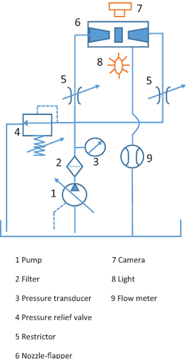
Figure 10 Experimental circuit employed in (Li et al., 2013).

Figure 11 (a) Representation of the cavitation phenomenon in a nozzle-flapper and (b) representation of the velocity and force components on a flapper (Li et al., 2013).
In (Aung and Li, 2014), an innovative flapper geometry was proposed in an attempt to reduce the intensity of the cavitation phenomenon. The proposed flapper shape is rectangular, having the potential to eliminate the source of cavitation given by the curved edge of traditionally used flappers. Figure 12 shows the comparison between a traditional flapper and the novel one in terms of contours of vapour fraction predicted for an operating pressure of 3 Mpa, 5 Mpa and 7 Mpa. The comparison reveals that cavitation intensity has lowered near the edges of the rectangular flapper, despite maintaining the same behaviour near the nozzle tip.
In (Yang et al., 2015a), the effectiveness of using a rectangular shape was further assessed. The rectangular shape flapper was also compared with a square shape one. It was noticed that the latter is also able to reduce cavitation compared to the traditional shape; however, the square shape is less effective than the rectangular one in reducing cavitation because it produces larger vortexes and significant propagation of jet flow.
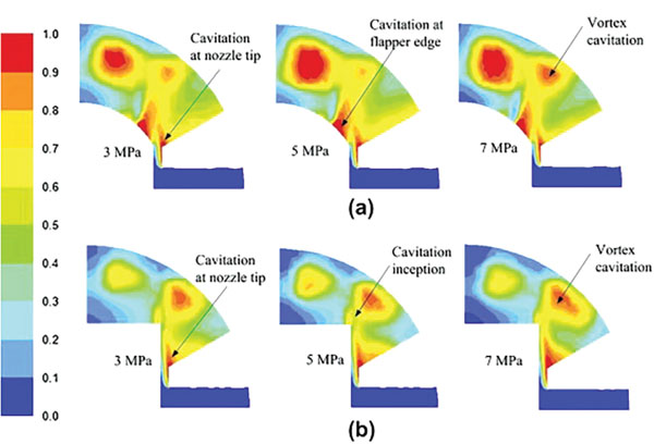
Figure 12 (a) Comparison between reference and (b) optimized flapper in terms of vapour fraction (Aung and Li, 2014).
The research papers analysed so far have focused on the simulation of steady state cavitation. Instead in (Zhang and Li, 2015), cavitation inside a nozzle-flapper pilot stage was simulated by using the Large Eddy Simulation (LES) approach provided by Ansys Fluent, which was able to predict the unsteadiness phenomenon associated with cavitation. In this case, only the upper part of the pilot stage flow field was simulated, adopting a computational grid of about 200000 cells. The inlet pressure was set to 1 MPa, 2 MPa and 3 MPa during the calculation, while the outlet pressure was considered equal to 0.5 bar. The Schnerr and Sauer model was used since it is the most compatible with the LES model among the available cavitation models. The effectiveness of the Schnerr and Sauer model was also proved in (Amirante et al., 2014c). An experimental apparatus, similar to that shown in Figure 10, was used by Zhang and Li 2015, in order to validate the numerical results. It consisted of a double nozzle–flapper assembly (composed of a flapper, two nozzles and two transparent covers at the front and back), a high speed video camera and an illuminating system (which allowed the flow field to be illuminated and observed conveniently), and a pump. The inlet and outlet pressures were measured by two pressure gauges and the flow rate was measured through a flow meter. The comparison between the experimental data and numerical predictions in terms of the flow rate showed a very good agreement, with the average difference being less than 4%. Moreover, the images captured by the camera were consistent with the numerical predictions of the vapour distribution along a symmetry plane. The results confirmed that the increase in the inlet pressure intensifies the cavitation intensity; in addition, the results showed that the increase in the inlet pressure increases both the frequency and the magnitude of the pressure oscillations in the nozzle-flapper pilot stage.
Other Research Studies
Modelling and Control
Electro-hydraulic servovalves can be difficult to control because of nonlinearities. In (Fink and Singh 1998), a discrete time sliding mode controller was designed to control the pressure drop across a load. A nonlinear transformation was presented to convert the system dynamics to a linear state space representation. The performance of the controller was numerically analysed and compared to a classical PID controller, showing very good results.
Proportional-integral-derivative (PID) controllers are widely applied to electro-hydraulic servo valves since they are easy to implement and highly efficient. In (Samakwong and Assawinchaichote 2016), the optimal tuning of the PID parameters was performed by using a Genetic Algorithm (GA). This technique was compared with other tuning techniques, showing that the genetic algorithm can optimize the PID controller parameters better than the Ziegler-Nichols tuning method.
In (Rashidy et al. 2003), the problem of identifying faults in hydraulic servovalves was addressed. A hierarchical neuro-fuzzy system was proposed to deal with the complex data and the interference among the phenomenological features of the faults. It was found that the hierarchical system is capable of detecting the faults, with a simple design procedure and high feasibility.
In (Brito et al. 2013), a Hammerstein model, where a static nonlinearity is followed by a linear system, was used to study a servovalve for aerospace applications. A polynomial NARMAX representation was considered and the model coefficients were evaluated through an extended least squares procedure, so that the parameter bias was avoided. The identification procedure is based on an initial frequency-domain analysis step. The objective is to gain some useful information about the system behavior so that one can define a proper structure for the Hammerstein model. The results showed that the identified model is able to represent the general nonlinear behaviour of servovalves.
Novel Configurations
In (Anderson and Li, 2002) and (Li, 2002), a servovalve based on pressure feedback instead of mechanical or electrical feedback was conceived. As shown in Figure 13, the first stage is a typical double nozzle-flapper valve. In contrast, the main stage is composed of two sliding spools, separated by a simple transition plate and connected via two pressure chambers; both spools are centred by two centring springs capable of providing null adjustment. When an electrical input is provided to the torque motor, it generates a torque, which in turn rotates the armature and flapper. As the flapper is displaced, for example, to the right, the nozzle opening on the right decreases and the opening on the left increases. This in turn raises P2 and lowers P1. The differential pressure P2 –P1 acts on the two ends of each spool, moving both of them upwards simultaneously. Such upward movement causes a corresponding increase in the differential pressure P2–P1, which has the effect of restoring the flapper to its neutral position.
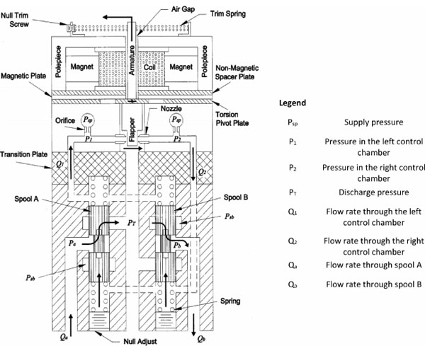
Figure 13 Two spool-valve with pressure feedback realised in (Anderson and Li, 2002).
In (Mondal & Datta, 2013), a similar architecture was studied, having two spools for the main stage instead of a single spool. The feedback was obtained by pressure. This valve architecture has the potential to reduce the costs substantially, give higher degree of adjustment and greater safety. It was demonstrated in simulation that such a low cost servovalve can provide acceptable performance. In (Mondal and Datta, 2017), the effects of the damping length on the two-stage two-spool servovalve were investigated. A simplified linear model was developed to capture the effect of damping length on the dynamic performance of the system. The model was realized in Matlab/Simulink taking into account the effect of axial flow force and fluid compressibility.
In (Yu et al., 2014), a novel rotary direct drive valve (RDDV) was introduced. It is composed of a rotary spool, a static sleeve, a valve body, valve covers and other accessories, as shown in Figure 14. This servovalve is designed in a rotating structure and its axially symmetric spool rotates within a certain angle range in the valve chamber. The servovalve orifices are formed by the matching between the square wave shaped land on the spool and the rectangular ports on the sleeve. In order to study the RDDV performance, theoretical models and CFD analysis were carried out. The results suggest that this novel and innovative structure for direct drive servovalves can reduce the flow force on the spool and improve valve frequency response characteristics.

Figure 14 3D representation of the rotary direct drive valve (RDDV) developed by (Yu et al., 2014).
Three Stage Valves
Some researchers actively investigate the key parameters of three stage electro-hydraulic servovalves to improve the performance. A detailed model was presented in (Liu et al., 2009). The results of the simulation and experimental test were consistent, which proves the validity of the model. Based on the study of the model, it was shown that the performances of three-stage electro-hydraulic servovalves are mainly affected by the performance of the pilot valve, the spool and sleeve, the position transducer and the servo controller, which shows that there are four main key technologies. The study results have a guiding role for developing higher performance three-stage electro-hydraulic servo valves. The effects of the design parameters on the performance of three-stage electro-hydraulic servovalves were also investigated in detail in (Istanto et al., 2017). To that end, a detailed mathematical model for a three-stage electro-hydraulic servovalve was developed along with a MATLAB/Simulink simulation model. The simulation results were compared with experimental data. It was shown that faster response in a three-stage elec-trohydraulic servovalve could be achieved by increasing the size of the orifices, reducing the flow force, and increasing the supply pressure in the pilot stage.
In (Sell et al., 2013), a novel three stage servovalve design was conceived. The primary stage is a Moog high speed servo valve which is used to direct high pressure flow (up to 200 bar) into an equal area actuator. This is directly attached to the main spool with its multiple grooves. These multiple grooves have the advantage of exposing a large flow area, 37.7mm2, for a small spool displacement, 0.1mm. The high flow gain makes the valve suited to digital hydraulics, giving both a high frequency of switching and a high flow rate. An accelerometer and position sensor are also incorporated into the valve housing, the former at the top and the latter the bottom of the valve (Sell et al., 2013).
Novel Actuation Concepts Based on Smart Materials
Electro-hydraulic two-stage servovalves adopting a nozzle-flapper, a deflector jet or a jet pipe as hydraulic amplification systems are widely used in aerospace and industrial sectors because of their reliability and good dynamic performance. However, they present a few disadvantages that are still unresolved. One of these disadvantages is the necessity for the pilot stage to have a quiescent flow rate to work (Hunt & Vaughan, 1996); although small compared to the maximum flow rate through the main stage, this internal leakage can consume a considerable proportion of the input power if the valve is at rest for long periods (Tamburrano et al., 2018a). The electromagnetic torque motor assembly is also a major issue with these valves because it is composed of many sensitive mechanical and electrical parts that penalize simplicity, set-up and manufacturing costs. Another criticism in terms of costs and duration of manufacture is represented by the flexure tube which supports the torque motor armature, because it needs to be manufactured very accurately to ensure the stiffness required. Several technical solutions have been proposed to date in an attempt to solve these issues.
In particular, a promising option is to use a piezoelectric actuator. The development of a piezovalve, namely a valve actuated by a piezoelectric actuator, can give the advantage of removing both the torque motor and the flexure tube from a servovalve design, thus reducing complexity and manufacturing costs.
A piezoelectric actuator exhibits mechanical strain and/or actuation force in response to an applied voltage. For a given input voltage, the higher the mechanical strain, the lower the actuation force exerted by the piezo-material. Figure 15 qualitatively shows the relationship between displacement, force and voltage. The maximum actuation force, named the blocking force, is obtained at zero strain. The maximum strain, at maximum voltage and zero force, is typically less than 0.15%. A piezoelectric actuator can provide very fast response times, but at the expense of high hysteresis (which can be as high as 20%) and high dependence on temperature variations, in addition to being subject to creep.
Servovalves Driven by Piezo-stack Actuators
One of the most common commercially available piezoelectric actuators is the stack-type, in which several piezo elements are joined together to form a multi-layer actuator (see Figure 16a). This type of actuator can provide very high blocking forces but low displacement. The higher the height of the stack, the higher the achievable displacement. As an example, a commercially available stack actuator constructed by a manufacturer is 15 cm in height and can produce a blocking force up to 2000 N with a free stroke of 200 μm (Noliac 2017).
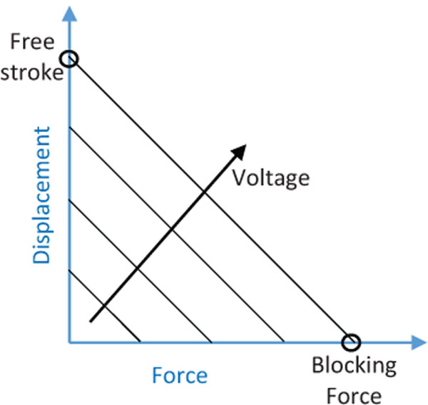
Figure 15 Displacement-Force-Voltage relationship for a piezoelectric actuator.
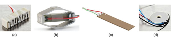
Figure 16 (a) Piezo-stack actuator; (b) amplified piezo-stack actuator; (c) bimorph actuator; (d) ring bender actuator.
In (Bang et al. 2003), the nozzle-flapper pilot stage was proposed to be controlled by stack-type piezoelectric elements. Two flapper moving mechanisms were proposed to compensate for the hysteresis problem and thermal expansion of the piezoelectric elements. The experimental results showed that the first flapper moving mechanism can provide a frequency response bandwidth of about 150 Hz, and the second system can provide a bandwidth of about 300 Hz at the supply pressure of 210 bar.
Reichert (2006) proposed to use four poppet valves as variable restrictors for the actuation of a main stage valve. Each poppet valve was proportionally driven by a piezoelectric stack. Each stack produced a stroke of 40 μm and a driving force of 2000 N at an operating voltage of 160 V. Electronic feedback of the main stage spool was used to achieve a closed loop control. A charge amplifier instead of a conventional voltage amplifier was used to drive the piezovalves. The disadvantage of this approach is the need for additional electronic circuitry and thus the increased complexity and cost of the control hardware, however hysteresis is dramatically reduced. The valve was capable of controlling 32 L/min at a pressure drop of 70 bar. At an input signal of 90%, the –3 dB frequency of the valve was 130 Hz and the –90 deg phase frequency was reported to be 250 Hz.
In (Branson et al., 2011), a valve directly actuated by a piezoelectric stack actuator was designed incorporating the Hörbiger plate principle, which utilizes multiple metering edges to allow high flowrates to be obtained at low pressure drops and small poppet displacements. A simulation model was used to evaluate the valve performance, and the model was validated using test data obtained from experimental tests undertaken on a prototype valve. Good agreement was obtained between the predicted and measured results and it was shown that the valve is capable of opening or closing fully in less than 1.5 ms, and can pass a flow of 65 l/min at a pressure drop of 20 bar.
Servovalves Driven by Amplified Piezo-stack Actuators
The main problem concerning the use of a stack actuator is due to the fact that the stack needs to be very large to achieve the necessary displacement for the valve actuation, which causes increase in the overall size and weight of a servovalve. To overcome this issue, amplification systems are adopted to increase the displacement of a stack actuator, resulting in a corresponding decrease in the maximum achievable blocking force. Figure 16b shows a commercially available flexure amplification system, in which the mechanical amplification is obtained thanks to an external elliptical shell which magnifies along the short axis the deformation occurring along the main axis (Cedrat 2017).
Lindler and Anderson (2002) developed a direct drive piezoelectric valve actuated by an amplified piezo-stack actuator, shown in Figure 17. A lever element was used to amplify the motion of the piezoelectric stack, from 0.06 mm to 0.3 mm. The maximum drive voltage of the actuator was 800 V. The maximum flow rate was limited to around 7.5 l/min, with a maximum operating pressure of about 100 bar. The experimental results showed that the valve had a good frequency response; the dynamic response was limited by a lightly damped mode at 340 Hz. Note that stacks have a thermal expansion coefficient, and any valve with spool driven directly by a stack, or with an amplified stack, has to be carefully designed to prevent significant thermal sensitivity.
A similar valve concept was developed in (Jeon et al., 2014), where a commercially available stack-type piezoelectric actuator was used for directly actuating the main stage valve. The free-displacement of the piezostack actuator is 0.1 mm at the maximum input voltage (150 V); the amplification system allowed a maximum spool position of about 0.35 mm to be reached. Also in this case, the dynamic performance retrieved experimentally was very good; the valve was tested with low inlet pressure (40 bar) and the flow rate was limited to about 7.65 l/min.
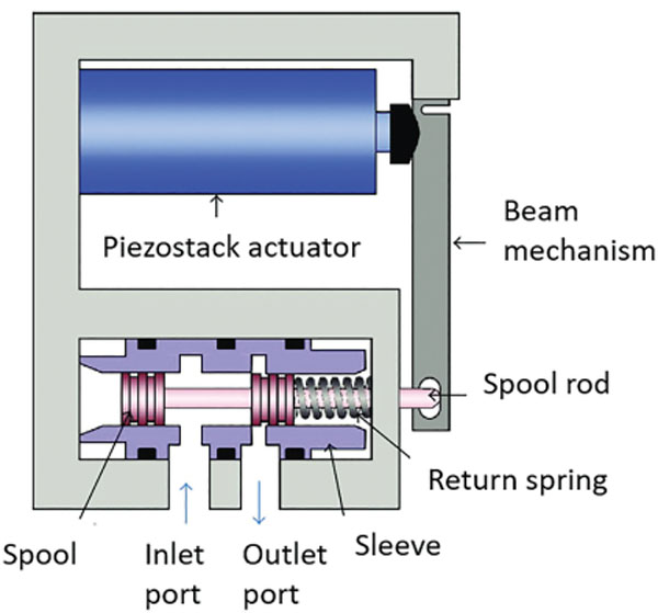
Figure 17 Direct actuated valve with amplification mechanism proposed in Lindler and Anderson (2002) and Jeon et al. (2014).
In (Karunanidhi and Singaperumal 2010a), a commercially available stack actuator with a flexure amplification system was used in place of a torque motor to move a flapper in a flapper nozzle pilot stage. The amplification system allowed a maximum displacement of 129 μm and a blocked force of 39 N for the piezoelectric actuator at an input voltage of 150 V. The measured value of the –90° phase frequency was 284 Hz; high levels of hysteresis were found in the valve operation.
Servovalves Driven by Bimorph Rectangular Actuators
As an alternative to stack actuators, bimorph rectangular benders (see Figure 16c) have also been developed (Thorlabs 2017); by means of a bending deformation, they can exhibit high displacement but with very low actuation forces. In this regard, in (Milecki 2006), (Zhu et al., 2010) and (Cheng et al., 2005), a piezoelectric bimorph actuator was used to actuate the flapper in place of a torque motor in a two-stage nozzle–flapper servovalve, as shown in Figure 18. In (Milecki, 2006), the spool position was measured to obtain electrical closed-loop position control; the actuator was capable of producing a maximum stroke of 160 μm and a blocking force of 2N at an operating voltage of 630 V. The dynamic response of the valve was reported to be compromised by stability issues. Hysteresis was also very large. In a similar approach (Sedziak 2010), a bimorph-actuated two-stage nozzle-flapper servovalve was developed. In this case, the valve control was open loop: the spool was centralised by springs so that its position was approximately proportional to the bimorph voltage. A maximum flow of 24 L/min was achieved with a supply pressure of 240 bar.
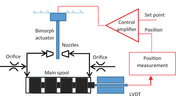
Figure 18 Scheme of application of a bimorph actuator for the control of a nozzle-flapper valve.
Sangiah et al. (2011, 2013) used a multilayer bimorph piezoelectric actuator replacing the conventional electromagnetic torque motor for the control of a deflector jet first stage. In the proposed configuration (see the scheme shown in Figure 19a), the bimorph actuator moves the deflector, which differentially directs the jet of fluid towards one of the two control ports, thus creating a pressure imbalance across the main spool in order to move it. A feedback wire was used to generate a restoring force that can re-centre the deflector and stop the spool at a fixed position, and the design trade-off between bimorph and feedback spring stiffnesses was studied. The valve prototype is shown in Figure 19b. Both numerical and experimental tests were carried out to assess the valve performance; the results showed that the –3 dB bandwidth was approximately 38 Hz, and the –90 deg phase lag frequency was about 50 Hz. Such implementation of a multilayer bimorph piezoelectric can provide several advantages, such as low voltage required (± 30 V) and high displacement of the deflector (±0.45 mm). However, the valve prototype exhibited high hysteresis (about ±4%). Although the actuation force available at the deflector jet was low (maximum blocking force = ±1 N), this was acceptable as flow forces in this type of pilot stage are very low.
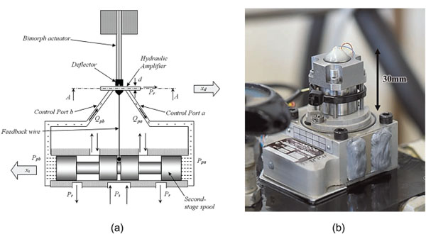
Figure 19 Deflector jet valve actuated by a bimorph rectangular actuator (Sangiah et al., 2013): (a) operating principle and (b) valve prototype.
Servovalves Driven by Ring Benders
In addition to stack actuators, amplified stack actuators and bimorph rectangular actuators, ring benders have also been constructed by several manufacturers (Noliac 2017). A ring bender (see Figure 16d) is a flat annular disc which deforms in a concave or convex fashion depending on the polarity of the applied voltage. A ring bender exhibits much greater displacement than a stack actuator of the same mass, and an increase in stiffness in comparison to similar size rectangular bimorph type actuators. The comparison, in terms of advantages and disadvantages, of the different types of piezo-actuators is reported in Table 4.
Bertin (2017) and Bertin et al. (2014) used ring bender actuators to develop a prototype of a pilot stage for nozzle flapper valves. A single ring bender and two ring benders, mounted in tandem to provide redundancy, were tested in place of the torque motor. A novel mounting mechanism employing o-rings was developed to secure the ring benders within the valve. An analytical model was developed and the predictions were compared with experimental results. The full stroke of the pilot stage valve was 150 μm when mounted in tandem with an inactive ring bender. The hysteresis of the valve was +/–10%. The pressures and flow at and between the control ports of the valve were consistent with the numerical predictions. The coupling between this pilot stage and a main stage spool is shown in Figure 20, with a linear variable displacement transducer (LVDT) being necessary to achieve a closed loop control system (Tamburrano et al., 2018b).
Table 4 Comparison of different types of piezo-electric actuators
| Type of Piezoelectric Actuator | Advantages | Disadvantages |
|---|---|---|
| Piezo-stacks | Very high actuation forces | Very low ratio of displacement to size, high hysteresis |
| Amplified | High actuation forces, | High complexity, low ratio of |
| piezo-stacks | Medium displacement | displacement to size, high hysteresis |
| Rectangular benders | High displacement | Very low actuation forces, high hysteresis |
| Ring bender | Medium displacement, Medium actuation forces | Lower forces than piezo-stacks and lower displacement than rectangular benders, high hysteresis |
In (Persson et al., 2015) and (Persson et al., 2016), a two stage servovalve was designed in which the first stage is composed of a four-way three-position small spool controlled by a piezoeletric ring bender. The flow through the small spool is capable of controlling the spool of a main stage according to the hydraulic scheme shown in Figure 21a. The servovalve body was constructed using additive manufacture (AM), which can provide significant benefits in weight and manufacturing labour cost, as well as providing additional design freedom. A picture of the valve prototype is shown in Figure 21b, while its representation is shown in Figure 21c. The positions of the main stage spool and the second stage spool are measured by two LVDTs. Voltages in the range ±100V are needed to control the ring bender. A mathematical model for the amplifier, first stage and second stage spool was developed and validated against experimental data. The valve presents very low internal leakage compared to common servovalves, which is an important advantage in terms of power consumption. The –90 deg phase frequency was around 100 Hz with closed loop spool position control. The valve pilot stage exhibits high hysteresis (up to 15%), but it can be reduced by using effective control techniques, so that the main stage spool position is accurately controlled.
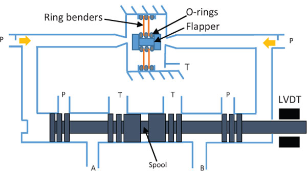
Figure 20 Schematic representation of the double nozzle-flapper piezovalve employing two ring benders, developed by Bertin et al., 2014.
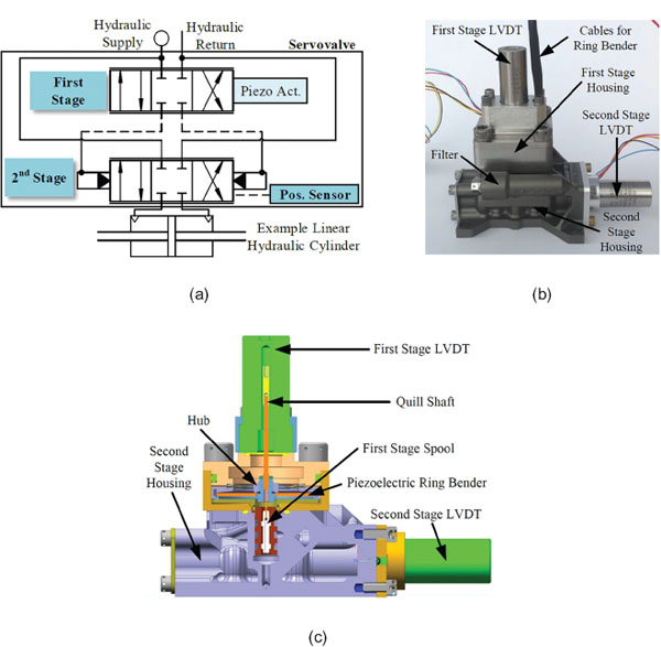
Figure 21 Piezovalve actuated by a first stage spool moved by a ring bender (Persson et al., 2015): (a) operating principle, (b) valve prototype, and (c) its representation.
In this regard, in (Persson et al., 2017) and (Stefanski et al., 2017) a generalised Prandtl–Ishlinskii model, fitted to experimental training data from the prototype valve, was used to model hysteresis empirically. This form of model is analytically invertible and is used to compensate for hysteresis in the prototype valve both open loop, and in several configurations of closed loop real time control system. The closed loop control configurations use PID (Proportional Integral Derivative) control with either the inverse hysteresis model in the forward path or in a command feedforward path. Performance is compared to both open and closed loop control without hysteresis compensation via step and frequency response results. Results show a significant improvement in accuracy and dynamic performance using hysteresis compensation.
Magnetostrictive Valves
As alternatives to piezo-electric actuators, giant magnetostrictive materials (GMMs) are new actuators appearing in recent years which are capable of producing strain, fast response speed, and large forces (Grunwald and Olabi 2008). These materials are able to change their shape and length under the influence of an external magnetic field, providing proportional, positive and repeatable expansion in microseconds. They experience rotation and reorientation which cause internal strains in the material structure; during this stretching process the cross-section is reduced in a way that the volume is kept nearly constant (Grunwald and Olabi 2008). Magnetostriction only occurs in a material at temperatures below the Curie temperature. Some properties of a commonly used GMM, namely Terfenol-D, are reported in Table 5. The maximum size of commercially available Terfenol-D rods is 65 mm in diameter and 175 mm in length (Claeyssen et al., 2003).
A deflector-jet servovalve using a GMM was developed for the first time in (Zhu and Li 2014). The GMM controls the deflector jet movement which in turns controls a main stage spool. As shown in Figure 22, the valve includes a bias and a driving solenoid coil (the bias solenoid coil generates a bias magnetic field, the driving solenoid coil generates an excitation magnetic field), a GMM rod, an output rod, a spring used to apply prestress onto the GMM rod (in order to obtain a larger magnetostrictive strain with the same magnetic field), and a screw that can be adjusted to vary the prestress according to the demand (Zhu and Li 2014).
Table 5 Properties of Terfenol-D, retrieved from (Yang et al., 2014) and (Claeyssen et al., 2003)
| Property | Value |
|---|---|
| Elongation | 0.2 % |
| Energy density | 20 kJ/m3 |
| Bandwidth | 10 kHZ |
| Hysteresys | 2% |
| Curie temperature | 380°C |
| Blocking force | Up to ~1.7 kN |

Figure 22 Deflector-jet pilot stage using a GMM developed in (Zhu and Li 2014): (a) operating principle, (b) experimental prototype.
Simulations and experimental tests were performed; the results showed that the valve has a rapid response and high bandwidth, demonstrating that the operational concept is viable.
In (Zhu et al., 2015), a novel configuration of a four-nozzle flapper servovalve driven by a giant magnetostrictive actuator (GMA) was developed. As shown in Figure 23, also in this case, the GMA comprises bias and driving solenoid coils for providing the bias magnetic field and an excitation magnetic field, a GMM rod, an output rod and a disc spring whose pre-stress can be varied by acting on a screw according to the demand. The four-nozzle flapper hydraulic amplifier is composed of one flapper (moved by the GMA), two fixed orifices and four nozzles located on both sides of the flapper.
The work presented in (Karunanidhi and Singaperumal 2010b) designed, built and integrated a magnetostrictive actuator with flexure amplifier to actuate the flapper in a double nozzle-flapper valve. In (Yang et al., 2014), a new type of direct drive valve actuated by a giant magnetostrictive material was designed. A new hydraulic amplifier with flexible pistons was built to increase the stroke of the GMA. Its structure was optimized through elasticity mechanic theory, finite element method and CFD method. The valve was modeled in AMESim and a prototype was constructed. Through simulation and experiments, the bandwidth of the designed valve is above 100 Hz while its flow reaches 30 L/min. In (Yang et al., 2015b), a multi-coupled model of the above-discussed pilot stage driven by a giant magnetostrictive actuator was established. In order to enhance its tracking performance, a compound control strategy was proposed: a feedforward controller based on the inverse of the hysteresis was employed, a semi-adaptive PID controller optimized by Particle Swarm Optimization accompanied the feedforward controller to deal with the disturbance of the system.
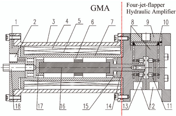
Figure 23 Structure of a GMM-based four jet flapper servovalve (Zhu et al. 2015): (1) left-end housing, (2) leak port, (3) shell, (4) bias magnetic coil, (5) driving solenoid coil, (6) support ring, (7) bobbin, (8) rear-end housing, (9) upper-end housing, (10) fixed orifice, (11) nozzle, (12) oil outlet, (13) flapper, (14) output rod, (15) disc spring, (16) GMM rod, (17) slide block and (18) adjusting screw.
Conclusions
This paper has provided an overview on the operating principles and mathematical models of servovalves, and an analysis of industrial units as well as a discussion of research investigations aimed at studying and improving these valves. Servovalves usually have a two-stage architecture, although three stage valves and directly-actuated valves are also designed. The main spool moves inside a bushing sleeve, which is provided with openings (slots) to allow flow rate metering as a function of the spool position. Compared to proportional valves, these valves present higher dynamic performance but also higher costs. Two stage valves take advantage of large actuation forces achieved through amplification systems which are usually in the form of a double-nozzle flapper, a pipe jet or a deflector jet.
These valves can be studied by means of analytical formulas which have been presented in the paper, being very useful for preliminary calculations of the main stage and pilot stage. Commercially available units have also been discussed in the paper, reporting practical examples. They have reached very high levels of performance compared to the first valves appeared on the market in World War II, in which the original configurations were based on the direct actuation. Aerospace servovalves usually employ mechanical feedback to meet safety requirements, but electrical feedback is sometimes used in industrial applications. The valve performance depends on the size of the valve: the larger the size of the valve, the higher the actuation forces but the lower the response speed and bandwidth.
A few research papers are available in the scientific literature that study these valves via CFD. In particular, intensive research has been focused on the prediction of the flow field in a double-nozzle pilot stage. It was shown that the main flow force acting on the flapper is accompanied by lateral forces resulting from the impact of radial jet reattachment on the flapper curved surface. In addition, it was predicted that the nozzle tips and flapper curved edge are the main sources of cavitation. These phenomena cause flapper instability and vibration. An innovative rectangular flapper geometry was designed, simulated and experimentally tested to successfully reduce the intensity of the cavitation phenomenon.
In addition to studying traditional configurations from a mathematical and a CFD point of view, novel configurations have been proposed in an attempt to reduce the main disadvantages of two-stage valves, namely the high internal leakage and the large number of mechanical and electrical parts that penalize simplicity, set-up and manufacturing costs. The use of smart materials, such as piezo-actuators, can be instrumental in developing alternative designs to traditional configurations. A piezoelectric actuator exhibits mechanical strain in response to an applied voltage. Piezo-stack actuators, amplified piezo-stack actuators, rectangular bimorph actuators and ring benders have been proposed as substitutes for torque motors. Valves with spools directly actuated by piezo actuators have been designed as well as two stage valves. Some prototype piezo-valves have been shown to provide advantages such as simplicity and high response speeds; other can reduce the internal leakage significantly. The main drawback is the high hysteresis experienced by piezo actuators; effective control strategies have been proposed to solve this issue.
As alternatives to piezo-electric actuators, giant magnetostrictive materials are being used as actuators for servovalves. These materials are able to change their shape and length under the influence of an external magnetic field, providing proportional, positive and repeatable expansion in microseconds. GMMs have been recently used to actuate the pilot stage of deflector jet valves and nozzle flapper valves.
Acknowledgment
This research was supported by the European Commission under the Marie Curie Intra-European fellowship Programme.
References
Amirante, R., Catalano, L. A., & Tamburrano, P. (2014a). The importance of a full 3D fluid dynamic analysis to evaluate the flow forces in a hydraulic directional proportional valve. Engineering Computations, 31(5), 898–922. https://doi.org/10.1108/EC-09-2012-0221
Amirante, R., Catalano, L. A., Poloni, C., & Tamburrano, P. (2014b). Fluid-dynamic design optimization of hydraulic proportional directional valves. Engineering Optimization, 46(10), 1295–1314. https://doi.org/10.1080/0305215X.2013.836638
Amirante, R., Distaso, E., & Tamburrano, P. (2014c). Experimental and numerical analysis of cavitation in hydraulic proportional directional valves. Energy Conversion and Management, 87, 208–219. https://doi.org/10.1016/j.enconman.2014.07.031
Amirante, R., Distaso, E., & Tamburrano, P. (2016). Sliding spool design for reducing the actuation forces in direct operated proportional directional valves: Experimental validation. Energy Conversion and Management, 119, 399–410. https://doi.org/10.1016/j.enconman.2016.04.068
Anderson, R. T., & Li, P. Y. (2002). Mathematical Modeling of a Two Spool Flow Control Servovalve Using a Pressure Control Pilot. Journal of Dynamic Systems, Measurement, and Control, 124(3), 420–427. https://doi.org/10.1115/1.1485287
Atchley, R. D. (1959). U.S. patent 2884907 R.D.Atchley. FiledAugust 1957 – issued May 1959.
Aung, N. Z., & Li, S. (2014). A numerical study of cavitation phenomenon in a flapper-nozzle pilot stage of an electrohydraulic servovalve with an innovative flapper shape. Energy Conversion and Management, 77, 31–39. https://doi.org/10.1016/j.enconman.2013.09.009
Aung, N. Z., Yang, Q., Chen, M., & Li, S. (2014). CFD analysis of flow forces and energy loss characteristics in a flapper-nozzle pilot valve with different null clearances. Energy Conversion and Management, 83, 284– 295. https://doi.org/10.1016/j.enconman.2014.03.076
Bang, Y. B., Joo, C. S., Lee, K. I., Hur, J. W., & Lim, W. K. (2003). Development of a two-stage high speed electrohydraulic servovalve systems using stack-type piezoelectric elements. In IEEE/ASME International Conference on Advanced Intelligent Mechatronics, AIM (Vol. 1, pp. 131–136). https://doi.org/10.1109/AIM.2003.1225084
Bertin, M. (2017). Piezoelectric actuation of an aero engine fuel metering valve. PhD Thesis. Department of Mechanical Engineering Centre for Power Transmission and Motion Control, University of Bath.
Bertin, M. J. F., Bowen, C. R., Plummer, A. R., & Johnston, D. N. (2014). An Investigation of Piezoelectric Ring Benders and Their Potential for Actuating Servo Valves. In Proceedings of the Bath/ASME Symposium on Fluid Power and Motion Control, Bath, United Kingdom, September 10– 12, 2014 (p. 6). https://doi.org/10.1115/FPMC2014-7852
Blackburn, J. F., Reethof, G., & Shearer, J. L. (1960). Fluid power control, The Mit press and Wiley.
Boyar, R. E., Johnson, B. A., & Schmid, L. (1955). Hydraulic Servo Control Valves. WADC Technical Report 55-29, Wright-Patterson Air Force Base, Ohio, 23–35.
Branson, D. T., Wang, F. C., Johnston, D. N., Tilley, D. G., Bowen, C. R., & Keogh, P. S. (2011). Piezoelectrically actuated hydraulic valve design for high bandwidth and flow performance. Proceedings of the Institution of Mechanical Engineers. Part I: Journal of Systems and Control Engineering, 225(3), 345–359. https://doi.org/10.1177/09596518JSCE1037
Brito, A. G., Filho, W. C. L., & Hemerly, E. M. (2013). Identification of a Hammerstein model for an aerospace electrohydraulic servovalve. In IFAC Proceedings Volumes (IFAC-PapersOnline) 46(19), 459–463. https://doi.org/10.3182/20130902-5-DE-2040.00119
Carson, T. H. (1960). U.S. patent 2934765. Filed Sept. 1955 – issued April 1960.
Cedrat. (2017). http://www.cedrat-technologies.com/en/products/actuators/apa.html. Accessed September 2017.
Cheng, G. M., Li, P., Yang, Z. G. E, S. J., & Liu, J.F. (2005). Double-nozzle piezoelectric servovalve. Guangxue Jingmi Gongcheng/Optics and Precision Engineering, 13(3), 276–282.
Claeyssen, F., Lhermet, N., & Maillard, T. (2003). Magnetostrictive actuators compared to piezoelectric actuators. In Proceedings of SPIE – The International Society for Optical Engineering.
Di Rito, G., & Galatolo, R. (2008). Experimental and theoretical study of the electrical failures in a fault-tolerant direct-drive servovalve for primary flight actuators. Proceedings of the Institution of Mechanical Engineers. Part I: Journal of Systems and Control Engineering, 222(8), 757–769. https://doi.org/10.1243/09596518JSCE588
El-Araby, M., El-Kafrawy, A., & Fahmy, A. (2011). Dynamic performance of a nonlinear non-dimensional two stage electrohydraulic servovalve model. International Journal of Mechanics and Materials in Design, 7(2), 99–110. https://doi.org/10.1007/s10999-011-9150-x
Fang, X., Yao, J., Yin, X., Chen, X., & Zhang, C. (2013). Physics-of-failure models of erosion wear in electrohydraulic servovalve, and erosion wear life prediction method. Mechatronics, 23(8), 1202–1214. https://doi.org/10.1016/j.mechatronics.2013.09.006
Fink, A., & Singh, T. (1998). Discrete sliding mode controller for pressure control with an electrohydraulic servovalve. Proceedings of the 1998 IEEE International Conference on Control Applications, 1(September), 378–382.
Ghasemi, E., Jazayeri, S. A., & Moosavian, S. A. A. (2008). Model improvement for a servovalve with force feedback and back pressure. In 2008 IEEE International Conference on Robotics, Automation and Mechatronics, RAM 2008 (pp. 895–900). https://doi.org/10.1109/RAMECH. 2008.4681461
Gordić, D., Babić, M., & Jovičić, N. (2004). Modelling of spool position feedback servovalves. International Journal of Fluid Power, 5(1), 37–51. https://doi.org/10.1080/14399776.2004.10781182
Gordić, D., Babić, M., Jovičić, N., & Milovanović, D. (2008). Effects of the variation of torque motor parameters on servovalve performance. Strojniski Vestnik/Journal of Mechanical Engineering, 54(12), 866–873.
Grunwald, A., & Olabi, A. G. (2008). Design of a magnetostrictive (MS) actuator. Sensors and Actuators, A: Physical, 144(1), 161–175. https://doi.org/10.1016/j.sna.2007.12.034
Hiremath, S. (2013). Modeling and simulation of fluid structure interaction in jet pipe electrohydraulic servovalve. International Journal of Recent Advances in Mechanical Engineering (IJMECH), 2(4), 1–14.
Hiremath, S. S., & Singaperumal, M. (2010). Fluid structure interaction in electrohydraulic servovalve: A finite element approach. In Proceedings of SPIE – The International Society for Optical Engineering (Vol. 7500).
Hunt, T., & Vaughan, N. (1996). The Hydraulic Handbook, 9th edition, copyright Elsevier science LTD.
Istanto, I., Kim, H. H., & Lee, I. Y. (2017). Effects of major design parameters on three-stage electro-hydraulic servovalve performance. In Lecture Notes in Electrical Engineering, 415 (LNEE), 459–468. https://doi.org/10.1007/978-3-319-50904-4_49
Jacob, McHenya, M., Zhang, S., & Li, S. (2011). A study of flow-field distribution between the flapper and nozzle in a hydraulic servovalve. Proceedings of 2011 International Conference on Fluid Power and Mechatronics, FPM 2011, 658–662. https://doi.org/10.1109/FPM.2011.6045844
Jeon, J., Han, C., Han, Y. M., & Choi, S. B. (2014). A new type of a direct-drive valve system driven by a piezostack actuator and sliding spool. Smart Materials and Structures, 23(7), 075002. https://doi.org/10.1088/0964-1726/23/7/075002
Karunanidhi, S., & Singaperumal, M. (2010a). Mathematical modelling and experimental characterization of a high dynamic servo valve integrated with piezoelectric actuator. Proceedings of the Institution of Mechanical Engineers. Part I: Journal of Systems and Control Engineering, 224(4), 419–435. https://doi.org/10.1243/09596518JSCE899
Karunanidhi, S., & Singaperumal, M. (2010b). Design, analysis and simulation of magnetostrictive actuator and its application to high dynamic servo valve. Sensors and Actuators, A: Physical, 157(2), 185–197. https://doi.org/10.1016/j.sna.2009.11.014
Li, L., Yan, H., Zhang, H., & Li, J. (2018). Numerical simulation and experimental research of the flow force and forced vibration in the nozzle-flapper valve. Mechanical Systems and Signal Processing, 99, 550–566. https://doi.org/10.1016/j.ymssp.2017.06.024
Li, P. Y. (2002). Dynamic Redesign of a Flow Control Servovalve Using a Pressure Control Pilot. Journal of Dynamic Systems, Measurement, and Control, 124(3), 428–434. https://doi.org/10.1115/1.1485288
Li, S., Aung, N. Z., Zhang, S., Cao, J., & Xue, X. (2013). Experimental and numerical investigation of cavitation phenomenon in flapper-nozzle pilot stage of an electrohydraulic servovalve. Computers and Fluids, 88, 590–598. https://doi.org/10.1016/j.compfluid.2013.10.016
Li, Y. (2016). Mathematical modelling and characteristics of the pilot valve applied to a jet-pipe/deflector-jet servovalve. Sensors and Actuators, A: Physical, 245, 150–159. https://doi.org/10.1016/j.sna.2016.04.048
Lin, S. J., & Akers, A. (1989). A Dynamic Model of the Flapper-Nozzle Component of an Electrohydraulic Servovalve. Journal of Dynamic Systems, Measurement, and Control, 111(1), 105–109. https://doi.org/10.1115/1.3153006
Lindler, J. E., & Anderson, E. H. (2002). Piezoelectric direct drive servovalve. In SPIE’s 9th Annual International Symposium on Smart Structures and Materials, 2002, San Diego, California, United States.
Liu, X., He, J., Ye, Z., Cong, D., & Han, J. (2009). Modeling and key technologies study of three-stage electro-hydraulic servo valve. In Proceedings – 2009 International Asia Conference on Informatics in Control, Automation, and Robotics, CAR 2009 (pp. 317–320). https://doi.org/10.1109/CAR.2009.78
Maré, J. -C., & Attar, B. (2008). Realistic modelling of electrohydraulic servovalves. In 6th International Fluid Power Conference – IFK 2008.
Maskrey, R. H., & Thayer, W. J. (1978). A Brief History of Electrohydraulic Servomechanisms. Journal of Dynamic Systems, Measurement, and Control, 100(2), 110–116. https://doi.org/10.1115/1.3426352
Mcnea, M., & Duan, S. S. (2013). The Effects of Orifice Sizes on a Hydraulic Servo Valve Control System. In ASME 2013 International Mechanical Engineering Congress and Exposition.
Merritt, H. (1967). Hydraulic Control System. John Wiley and Sons.
Milecki, A. (2006). Modelling & investigations of electrohydraulic servo valve with piezo element. Maszyn i Automatyzacji,Archiwum Technologii, 26(2), 177–184.
Mondal, N., & Datta, B. (2017). Effect of damping length on dynamic performance of two-stage two-spool electrohydraulic servovalve. Lecture Notes in Mechanical Engineering, Part F8, 1213–1222. https://doi.org/10.1007/978-81-322-2743-4_115
Mondal, N., & Datta, B. N. (2013). A study on electro hydraulic servovalve controlled by a two spool valve. International Journal of Emerging Technology and Advanced Engineering An ISO Certified Int. Journal, 3(9001), 479–484. Retrieved from www.ijetae.com
Moog. (1953). U.S. Patent 2625136 W.C. Moog filed April 1950-issued January 1953.
Moog. (1965). U.S. Patent 2767689 W.C. Moog filed May 1953-issued October 1965.
Moog. (2017). http://www.moog.com/products/servovalves-servo-proportional-valves.html. Accessed September 2017.
Noliac. (2017). http://www.noliac.com/products/actuators/plate-stacks/. Accessed September 2017.
Pan, X., Wang, G., & Lu, Z. (2011). Flow field simulation and a flow model of servovalve spool valve orifice. Energy Conversion and Management, 52(10), 3249–3256. https://doi.org/10.1016/j.enconman.2011.05.010
Parr, A. (2011). Hydraulics and Pneumatics (Third edition) A technician’s and engineer’s guide. (Elsevier, Ed.). Butterworth-Heinemann, The Boulevard, Langford Lane, Kidlington, Oxford OX5 1GB, UK.
Persson, J., Plummer, A., Bowen, C., & Elliott, P. (2017). Non-linear Control of a Piezoelectric Two Stage Servovalve. The 15th Scandinavian International Conference on Fluid Power, SICFP’17, June 7-9, 2017, Linköping, Sweden.
Persson, J., Plummer, A. R., Bowen, C. R., & Brooks, I. (2015). Design and Modelling of a Novel Servovalve Actuated by a Piezoelectric Ring Bender. In ASME/BATH 2015 Symposium on Fluid Power and Motion Control, October 12–14, 2015, Chicago, Illinois, USA. https://doi.org/10.1115/FPMC2015-9576
Persson, J., Plummer, A. R., Bowen, C. R., & Elliott, P. L. (2016). Dynamic Modelling and Performance of a Two Stage Piezoelectric Servovalve. In 9th FPNI Ph. D. Symposium on Fluid Power. American Society of Mechanic Engineers.
Plummer, A. (2016). Electrohydraulic servovalves – past, present, and future. 10th International Fluid Power Conference (IFK2016), 405–424.
Rashidy, H., Rezeka, S., Saafan, A., & Awad, T. (2003). A hierarchical neuro-fuzzy system for identification of simultaneous faults in hydraulic servovalves. Proceedings of the 2003 American Control Conference, 2003, 5, 4269–4274. https://doi.org/10.1109/ACC.2003.1240507
Reichert, M. (2006). High response hydraulic servovalve with piezo-actuators in the pilot stage. Olhydraulik and Pneumatik, 12, 1–17.
Samakwong, T., & Assawinchaichote, W. (2016). PID Controller Design for Electro-hydraulic Servo Valve System with Genetic Algorithm. In Procedia Computer Science (Vol. 86, pp. 91–94). https://doi.org/10.1016/j.procs.2016.05.023
Sangiah, D. K., Plummer, A. R., Bowen, C. R., & Guerrier, P. (2011). Modelling and Experimental Validation of a Novel Piezohydraulic Servovalve. In ASME 2011 Dynamic Systems and Control Conference and Bath/ASME Symposium on Fluid Power and Motion Control, Volume 2 (Vol. 2, pp. 343–350). https://doi.org/10.1115/DSCC2011-5940
Sangiah, D. K., Plummer, A. R., Bowen, C. R., & Guerrier, P. (2013). A novel piezohydraulic aerospace servovalve. Part 1: Design and modelling. Proceedings of the Institution of Mechanical Engineers. Part I: Journal of Systems and Control Engineering, 227(4), 371–389. https://doi.org/10.1177/0959651813478288
Sedziak, D. (2010). Investigations of Electrohydraulic Servo Valves with Piezo Bender as Control Element. In 7th International Fluid Power Conference (pp. 1–12).
Sell, N. P., Johnston, D. N., Plummer, A. R., & Kudzma, S. (2013). Control of a fast switching valve for digital hydraulics. The 13th Scandinavian International Conference on Fluid Power, 497–503.
Stefanski, F., Minorowicz, B., Persson, J., Plummer, A., & Bowen, C. (2017). Non-linear control of a hydraulic piezo-valve using a generalised Prandtl– Ishlinskii hysteresis model. Mechanical Systems and Signal Processing, 82, 412–431. https://doi.org/10.1016/j.ymssp.2016.05.032
Tamburrano, P., Amirante, R., Distaso, E., & Plummer, A. R. (2018a). A novel piezoelectric double-flapper servovalve pilot stage: Operating principle and performance prediction. In Bath/ASME Symposium on Fluid Power and Motion Control FPMC. 2018, 12–14 September 2018, University of Bath, Bath (UK).
Tamburrano, P., Amirante, R., Distaso, E., & Plummer, A. R. (2018b). Full simulation of a piezoelectric double nozzle flapper pilot valve coupled with a main stage spool valve. Energy Procedia 148, 487–494.
Tamburrano, P., Plummer, A. R., Distaso, E., & Amirante, R. (2019). A review of direct drive proportional electrohydraulic spool valves: industrial state-of-the-art and research advancements. Journal of Dynamic Systems, Measurement, and Control, 141(2), 020801. doi:10.1115/1.4041063.
Thorlabs. (2017). https://www.thorlabs.com/thorproduct.cfm?partnumber=PB4NB2W. Accessed September 2017.
Tinsley. (1949). English patent 620688. Applied May 1946-accepted March 1949.
Urata, P. E., Suzuki, K., & Mori, T. (2008). The Stiffness of Armature Support in Servovalve Torque-Motors. In 6th International Fluid Power Conference – IFK 2008 (pp. 113–126).
Wolpin, M. P. (1965). U.S. patent 3209782 M.P. Wolpin. Filed May 1955 – issued October 1965.
Yang, Z., He, Z., Li, D., Xue, G., & Cui, X. (2014). Hydraulic amplifier design and its application to direct drive valve based on magnetostrictive actuator. Sensors and Actuators, A: Physical, 216, 52–63. https://doi.org/10.1016/j.sna.2014.05.005
Yang, Q., Aung, N. Z., & Li, S. (2015a). Confirmation on the effectiveness of rectangle-shaped flapper in reducing cavitation in flapper-nozzle pilot valve. Energy Conversion and Management, 98, 184–198. https://doi.org/10.1016/j.enconman.2015.03.096
Yang, Z., He, Z., Li, D., Yu, J., Cui, X., & Zhao, Z. (2015b). Direct drive servo valve based on magnetostrictive actuator: Multi-coupled modeling and its compound control strategy. Sensors and Actuators, A: Physical, 235, 119–130. https://doi.org/10.1016/j.sna.2015.09.032
Ye, J., Xiong, Y., Li, F., & Chen, S. (2010). Experimental study of effects of air content on cavitation and pressure fluctuations. Journal of Hydrodynamics, 22(5), 634–638. https://doi.org/10.1016/S1001-6058(09)60097-4
Yu, J., Zhuang, J., & Yu, D. (2014). Modeling and analysis of a rotary direct drive servovalve. Chinese Journal of Mechanical Engineering, 27(5), 1064–1074. https://doi.org/10.3901/CJME.2014.0725.127
Zhang, K., Yao, J., & Jiang, T. (2014). Degradation assessment and life prediction of electro-hydraulic servo valve under erosion wear. Engineering Failure Analysis, 36, 284–300. https://doi.org/10.1016/j.engfailanal.2013. 10.017
Zhang, S., & Li, S. (2015). Cavity shedding dynamics in a flapper-nozzle pilot stage of an electro-hydraulic servovalve: Experiments and numerical study. Energy Conversion and Management, 100, 370–379. https://doi.org/10.1016/j.enconman.2015.04.047
Zhu, L., Shiju, E., Zhu, X., & Gao, C. (2010). Development of Hydroelectric Servo-Valve Based on Piezoelectric Elements. In 2010 Int. Conf. Mech. Autom. Control Eng. MACE2010 (pp. 3330– 3333).
Zhu, Y., & Li, Y. (2014). Development of a deflector-jet electrohydraulic servovalve using a giant magnetostrictive material. Smart Materials and Structures, 23(11). https://doi.org/10.1088/0964-1726/23/11/115001
Zhu, Y., Yang, X., & Wang, X. (2015). Development of a four-nozzle flapper servovalve driven by a giant magnetostrictive actuator. Proceedings of the Institution of Mechanical Engineers. Part I: Journal of Systems and Control Engineering, 229(4), 293–307. https://doi.org/10.1177/0959651814565829
Biographies

Paolo Tamburrano, PhD, is a mechanical engineer. As of July 2018, he is a Marie Curie research fellow at the University of Bath and an assistant professor at the Polytechnic University of Bari. He received the doctorate degree from the Polytechnic University of Bari with dissertation of the thesis titled “Fluid dynamic design optimization of mechanical and energy systems”. His research interests regard servovalves, proportional valves, piezo actuators, renewable energies, gas turbines, combined cycles, ORC, heat exchangers, internal combustion engines, cyclone separators. To date, he is co-author of 40 papers indexed in Scopus.

Andrew R. Plummer received his Ph.D from the University of Bath in 1991, for research into control of electro-hydraulic systems. He worked as a research engineer for Thales from 1990, developing flight simulator control technology, before joining the University of Leeds in 1994. From 1999 until 2006 he was global control systems R&D manager for Instron, manufacturers of materials and structural testing systems. He is now Director of the Centre for Power Transmission and Motion Control, University of Bath, and has published 160 papers in the field of motion and force control, many relating to electro-hydraulic servo-systems. Prof. Plummer is Past Chair of the Institution of Mechanical Engineers Mechatronics Informatics and Control Group and also the UK Automatic Control Council, and is Associate Editor of both the International Journal of Fluid Power and Control Engineering Practice. He is Chair of the Global Fluid Power Society.

Elia Distaso was born in Foggia on July 5, 1989. Graduated with honors in Mechanical Engineering at Polytechnic of Bari (Italy) in 2013, defending a Master’s Thesis based on an experimental work carried out at the FCA Research Center in Foggia (Italy). At the beginning of 2017, he received his Ph.D. from Polytechnic of Bari (Italy). From 2014 to 2016, he worked as Honorary Associate/Fellow (visiting scholar) at the Engine Research Center of University of Wisconsin-Madison, USA, were he worked on soot modeling under the guidance of Emeritus Professor Rolf D. Reitz. He is currently a post-doc fellow at the Polytechnic of Bari and his research activities concern the study of the combustion and emission formation processes, the analysis and the design of energy generation and heat-exchange systems, the experimental and numerical analysis of multi-phases flows with applications in the design of proportional valves by means of optimization techniques.

Riccardo Amirante received the first degree (5 years) with honours in Civil Engineering during Academic Years 1991/92 and the Ph.D. in “Machine engineering” in 1997, both from the Polytechnic University of Bari. He has been assistant professor at the University of Molise since from 1996 and is assistant professor of Energy systems, Internal Combustion Engines and Turbomachinery at the Polytechnic University of Bari from 2000. He has been associate professor from 2012 and full professor from 2017. Initially his research interests are in the field of fluid dynamic design problems applied to horizontal centrifugal separators and with their applications to industrial process. During this period, he obtained the first national prize for the better scientific paper about olive oil industry. Successively his research interests are in the field of Hydraulic transmissions, and he is actually first manager of Hydraulic and pneumatic laboratory of Department. He strongly cooperated in many national research projects. During the last years, he teaches many courses in University of Molise and Polytechnic University di Bari: Fluid Automation, Hydraulic transmissions, Agro alimentary machineries and plants, Energy systems, and so on. He is co-author of about 100 papers, most of which presented at international conferences or published in international journals.
International Journal of Fluid Power, Vol. 20 1, 53–98.
doi: 10.13052/ijfp1439-9776.2013
© 2019 River Publishers