Study on Dynamic Characteristics of Negative Flow Control Variable Axial Piston Pump for Hydraulic Excavator
Jin-yan Shi and Ke-chang Zhang*
Hunan Railway Professional Technology College, ZhuZhou 412001, China
E-mail: zhangkechang2008@163.com
*Corresponding Author
Received 14 July 2021; Accepted 12 August 2021; Publication 06 September 2021
Abstract
Hydraulic excavator is important mechanical equipment in engineering construction, which is widely used in mining enterprises, construction industry, etc. Variable axial piston pump is the main power component of hydraulic excavator. The negative flow control variable axial piston pump is deduced and the mathematical model is established. The dynamic simulation model of negative flow control variable axial piston pump is built by using SIMULINK in MATLAB software, and the simulation analysis is carried out. The influence of the main parameters of negative flow control mechanism on the dynamic characteristics of negative flow control variable axial piston pump is obtained, which provides a reference for the parameter design of negative flow control mechanism.
Keywords: Hydraulic excavator, negative flow control, variable axial piston pump, dynamical characteristics.
1 Introduction
The rapid development of China’s equipment manufacturing industry provides a good opportunity for the development of hydraulic transmission technology. Hydraulic transmission technology has many outstanding advantages, such as high power density, fast response speed, smooth movement and so on. It is widely used in equipment manufacturing, engineering machinery, aerospace, mining and metallurgy, national defense industry, transportation and other fields. Hydraulic excavators generally use constant speed diesel engine driven variable hydraulic pump to provide power for the car body, so that it can cope with most of the bad working conditions. Due to the characteristics of low cost, flexible application, multi-function and wide use, hydraulic excavator has become the main growth point of excavator market.
Andrea Bedotti et al. proposed an energy-efficient solution for excavators equipped with load-sensing hydraulic systems, saving 15% of their fuel [1]. Jinyan Shi et al. proposed K3V63 variable displacement pump integrates the total power control, the variable power control and the negative flow control. The negative flow control realizes the proportional relationship between the control pressure and the flow through the reasonable design of the mechanism [2]. Xiao Q et al. proposed the constant working point control strategy of hydraulic excavator engine, and studied it in the simulation experiment system. The research showed that the dynamic working point control strategy can improve the distribution of engine working points [3]. Jin-yan SHI et al. established the mathematical model of hydraulic excavator axial piston variable pump total power control, using Matlab software to carry out analysis, get static characteristic curve, and carried out the parameter optimization design [4].
Hydraulic excavator is very important mechanical equipment in engineering construction, which is widely used in mining enterprises, construction industry, etc. When the main control valve of the negative flow control hydraulic excavator is in the middle position, it can reduce the output flow of variable axial piston pump, adjust the output flow of hydraulic pump according to the demand, improve the speed regulation performance of hydraulic system, and realize energy-saving control. Figure 1 is the relationship between pressure and flow of hydraulic excavator negative flow control [5–7].
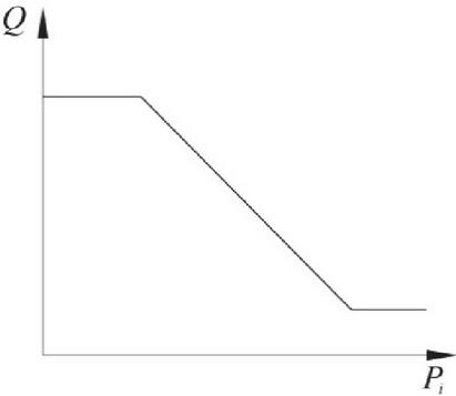
Figure 1 The relationship between pressure and flow of negative flow control.
The negative flow control of hydraulic excavator can realize the energy-saving control of hydraulic excavator, so it is important to study the dynamic characteristics of the variable axial piston pump with negative flow control. The paper analyses the principle of the control mechanism of the variable axial piston pump with negative flow control, establishes the simulation model and carries on the simulation analysis. The influence of the main parameters of negative flow control mechanism on the dynamic characteristics of negative flow control variable axial piston pump is obtained, which provides a reference for the parameter design of negative flow control mechanism [8–12].
2 Principle of Negative Flow Control Mechanism of Variable Axial Piston Pump
The negative flow control mechanism of hydraulic excavator variable axial piston pump is shown in Figure 2. The negative flow control mechanism is composed of servo valve stem 1, pins 2, 3, 4, 5 and 6, feedback fork 7, connecting rod 8, servo piston 9 and control piston 10. The basic principle of the negative flow control mechanism of the variable axial piston pump is: the feedback fork 7 and the connecting rod 8 drive the servo valve 1 to move, the big end of the servo piston 9 is connected with the oil outlet of the pump, and the high-pressure oil is connected. If the inclined angle of the swash plate becomes smaller, the output flow of the pump will be reduced [13–16].
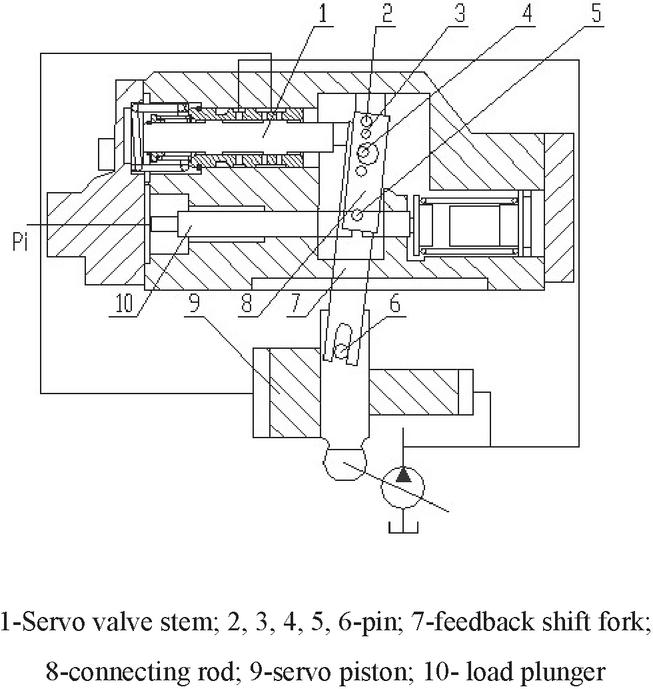
Figure 2 Schematic diagram of negative flow control mechanism of variable axial piston pump.
3 Kinematics Analysis of Negative Flow Control Mechanism of Variable Axial Piston Pump
According to the dynamics principle, the force balance equation of the load plunger 10 can be obtained as:
| (1) |
While, the is control pressure; is the area of the plunger; is the initial force of the spring; is spring stiffness; is load plunger displacement; is comprehensive mass of negative flow control load plunger; is viscous damping coefficient between the negative flow control load plunger and the valve body; is the connecting rod exerts force on the load plunger through the pin.
The displacement formula of the servo valve stem is
| (2) |
While, is the initial spring force of the valve stem; is comprehensive quality of valve stem; is displacement of the valve stem drawn by the load plunger; is viscous damping coefficient of valve stem and valve sleeve; is the spring stiffness of the valve stem; ; .
The relationship between the displacement of the servo plunger and the inclination of the swash plate is satisfied:
| (3) |
While, is servo plunger displacement; is swash plate control arm length; is swash plate inclination angle.
When the displacement of the servo plunger is small, the incremental expression of the inclination angle of the servo plunger to the swash plate can be expressed as
| (4) |
According to the dynamics principle, the torque balance equation of the swash plate is
| (5) |
While, is the force of the servo plunger acting on the swash plate; is moment of inertia of the swash plate around the fixed point; is viscous damping coefficient of swash plate rotation; is the resistance moment coefficient of the swash plate; is load pressure; is the resistance torque experienced by the swash plate rotation.
According to the dynamics principle, the force balance equation of the servo plunger is
| (6) |
While, is large end area of servo plunger; is the area of the small end of the servo plunger; is servo plunger large end pressure; is viscous damping coefficient of servo plunger and pump body; is servo plunger quality.
From formula (4), (5), (6), the total force balance equation of the plunger and the swash plate can be obtained
| (7) |
While,
The feedback of the servo plunger to the valve stem is simplified as a proportional link, and the valve stem displacement equation can be obtained as
| (8) |
While, is servo valve stem opening.
The flow equation of the servo valve stem valve port is
| (9) |
While, is valve port flow coefficient; is oil density; is gradient of valve port area.
According to the flow continuity equation, the flow equation of the servo plunger can be obtained as
| (10) |
While, is leakage coefficient of servo plunger; is servo plunger big end controls cavity volume; is the elastic modulus of oil [17–22].
4 Simulation Model of Negative Flow Control Mechanism of Variable Axial Piston Pump
4.1 Dynamic Mathematical Model
The theoretical flow equation of the pump is
| (11) |
While, is the output flow rate coefficient; is the maximum stroke of the servo plunger.
According to the flow continuity equation, the continuity equation of the system can be obtained as
| (12) |
While, is the actual output flow of the pump.
From formula (2) and (7), the relationship between the opening of the servo valve stem () and the control pressure () and the displacement of the servo plunger () can be obtained.
For the valve-controlled servo plunger part, the state variables of the control system are set as: , , , the state equation of the control system can be written as
| (13) |
4.2 Simulation Block Diagram Negative Flow Control Mechanism
According to the established dynamic mathematical model of negative flow control mechanism, select the required modules in the SIMULINK toolbox of MATLAB Software, and fill in the corresponding variable symbols in the parameter settings of each module, connect all the modules to obtain the simulation of negative flow control mechanism block diagram, as shown in Figure 3. In the simulation of negative flow control mechanism, the control pressure is directly used as the input signal.
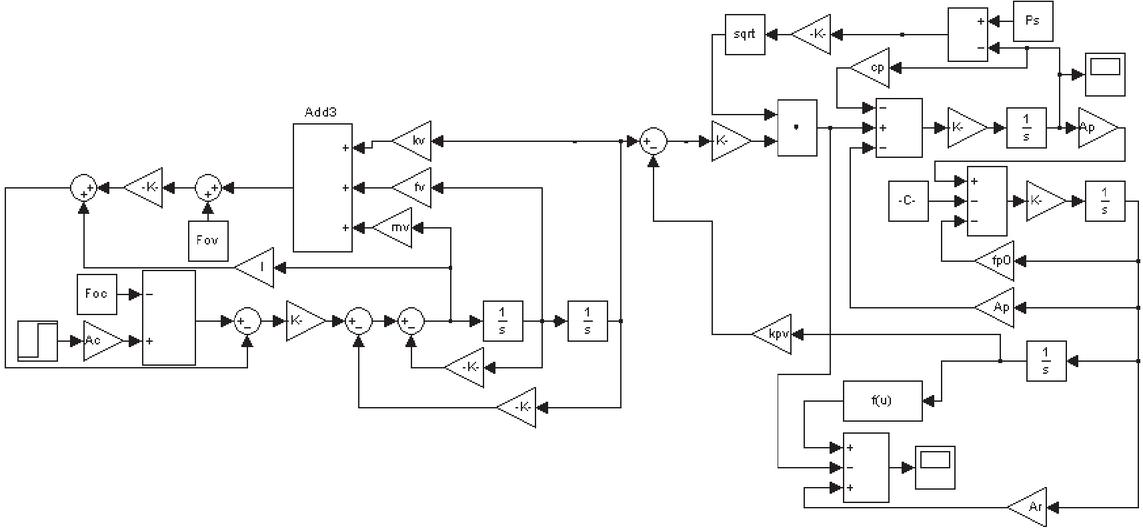
Figure 3 Simulation block diagram of negative flow control mechanism.
5 Dynamic Characteristics Simulation and Analysis of Negative Flow Control Pump
In the simulation model of Figure 3, the input control pressure is 1 MPa, 1.5 MPa, 2.0 MPa respectively, and the dynamic response curve of the output flow of the negative flow control pump is obtained as shown in Figure 4.
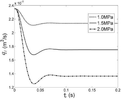
Figure 4 Step response curve of the output flow of the pump.
From the simulation results, the dynamic response characteristics of negative flow control are shown in Table 1. is the rise time, that is the time required for the response curve from zero to the first steady state value. is the adjustment time, that is the time required the difference between the response curve and the steady-state value reaches the allowable error, and has been kept in this allowed error within. is the maximum overshoot, which is the difference between the extreme value of the response curve (output) and the steady-state value.
Table 1 The dynamic response characteristics of negative flow control
| Control Pressure (MPa) | Steady State Value (m/s) | (ms) | (ms) | (m/s) |
| 1 | 32 | 64 | ||
| 1.5 | 30 | 66 | ||
| 2 | 31 | 66 |
From the curve in Figure 4 and the performance index data in Table 1, it can be seen that the rise time of the pump response is about 30 ms, and the adjustment time is about 60 ms, indicating that the pump has a fast response speed; as the input control pressure increases, the system becomes negative. The steady-state value of flow control output flow decreases and the dynamic characteristics do not change significantly.
6 Parameters Influence on the Dynamic Characteristics of Negative Flow Control Pump
6.1 The Influence of the Load Plunger Area
When the diameter of the negative flow control mechanism load plunger is 7 mm, 8 mm and 9 mm respectively, the response curve of the pump output flow is obtained by the simulation calculation as shown in Figure 5.
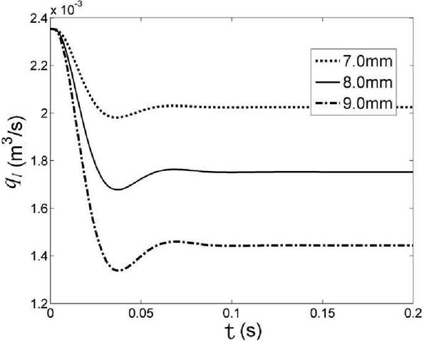
Figure 5 Output flow curve of pump under different load plunger area.
The dynamic response characteristics obtained from the simulation results are shown in Table 2.
Table 2 Dynamic characteristics of negative flow control with different load plunger area
| Diameter (mm) | Steady-state Value (m/s) | (ms) | (ms) | (m/s) |
| 7 | 31 | 66 | ||
| 8 | 30 | 66 | ||
| 9 | 29 | 67 |
From the curve of Figure 5 and the performance index data in Table 2, it can be seen that the steady-state value of pump output flow will change when the load plunger diameter is changed, but it has little effect on the dynamic characteristics. As the diameter of the load plunger increases, the steady-state value of the pump output flow decreases under the same control pressure.
6.2 The Influence of Load Plunger Spring Diameter
The average diameter of the load plunger spring is 16 mm, 17 mm and 18 mm respectively, and the dynamic response process of the pump output flow was observed. Running the simulation model, Figure 6 is the obtained dynamic response curve.
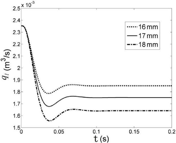
Figure 6 Output flow curve of pump under different load plunger spring diameter.
The dynamic response characteristics obtained from the simulation results are shown in Table 3.
Table 3 Dynamic characteristics of negative flow control pump with different load plunger spring diameter
| Diameter (mm) | Steady-state Value (m/s) | (ms) | (ms) | (m/s) |
| 16 | 31 | 66 | ||
| 17 | 30 | 66 | ||
| 18 | 31 | 67 |
From the curve of Figure 6 and the performance index data in Table 3, it can be seen that changing the spring diameter of load plunger has no effect on the dynamic characteristics of negative flow control pump, only can change the steady-state value of pump output flow. With the increase of load plunger spring diameter, the steady-state value of pump output flow increases under the same negative flow control pressure.
6.3 The Influence of Servo Valve Stem Spring Diameter
When the average diameter of servo stem spring is 13 mm, 14 mm and 15 mm respectively, the dynamic response curve is obtained in Figure 7.
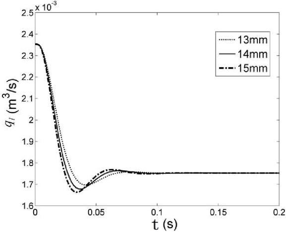
Figure 7 Output flow curve of pump under different servo valve stem spring diameter.
The dynamic response characteristics obtained from the simulation results are shown in Table 4.
Table 4 Dynamic characteristics of negative flow control pump with different servo valve stem spring diameter
| Diameter (mm) | Steady-state Value (m/s) | (ms) | (ms) | (m/s) |
| 13 | 39 | 65 | ||
| 14 | 30 | 66 | ||
| 15 | 22 | 72 |
Changing the servo valve stem spring diameter does not affect the output flow stability of variable displacement pump, and its dynamic characteristics will be changed. With the increase of the average diameter of the servo stem spring, the stiffness of the spring decreases, the overshoot of the system response increases and the stability becomes worse. But at this time the response rise time reduces, the response changes quickly.
6.4 The Influence of Large End Diameter of Servo Plunger
When the large end diameter of the servo plunger is changed, the small end diameter of the servo plunger is also changed, and the ratio between them is still 2:1. Under the initial condition, the large and small end diameters of the servo plunger are 32 mm and 16 mm respectively, and the step length is 4 mm, so that the large end diameters of the servo plunger are 28 mm, 32 mm and 36 mm respectively, Figure 8 is a series of curves obtained by changing the large end diameter of servo plunger.
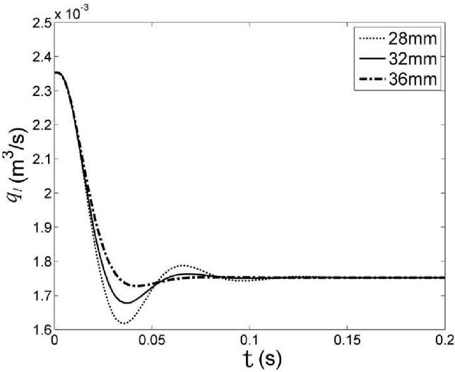
Figure 8 Output flow curve of pump under different large end diameter of servo plunger.
According to the simulation results, the dynamic response characteristics of the negative flow control pump while changing the large end diameter of the servo plunger are shown in Table 5.
Table 5 Dynamic characteristics of negative flow control pump with different large end diameter of servo plunger
| Diameter (mm) | Steady-state Value (m/s) | (ms) | (ms) | (m/s) |
| 28 | 23 | 104 | ||
| 32 | 30 | 66 | ||
| 36 | 43 | 64 |
From Figure 8 and Table 5, it can be seen that the dynamic characteristics of the negative flow control pump change obviously while changing the large end diameter of the servo plunger. With the increase of the diameter, the steady-state value of the pump output flow remains unchanged, the rise-time decreases, the response increases, the overshoot increases significantly, the oscillation is obviously, and the adjustment time increases. On the premise that the response time of the system can meet the requirement, the stability of the system can be ensured by increasing the large end diameter of the servo plunger.
7 Conclusions
(1) Under the initial parameters, the dynamic response of the negative flow control pump can meet the conditions of fast response time and small overshoot, and has better dynamic quality.
(2) The steady-state value of pump output flow will change when the load plunger diameter is changed, but it has little effect on the dynamic characteristics. As the diameter of the load plunger increases, the steady-state value of the pump output flow decreases under the same control pressure.
(3) Changing the spring diameter of load plunger has no effect on the dynamic characteristics of negative flow control pump, only can change the steady-state value of pump output flow. With the increase of load plunger spring diameter, the steady-state value of pump output flow increases under the same negative flow control pressure.
(4) Changing the servo valve stem spring diameter does not affect the output flow stability of variable displacement pump, and its dynamic characteristics will be changed. With the increase of the average diameter of the servo stem spring, the stiffness of the spring decreases, the overshoot of the system response increases and the stability becomes worse. But at this time the response rise time reduces, the response changes quickly.
(5) The dynamic characteristics of the negative flow control pump change obviously while changing the large end diameter of the servo plunger. With the increase of the large end diameter, the steady-state value of the pump output flow remains unchanged, the rise-time decreases, the response increases, the overshoot increases significantly, the oscillation is obviously, and the adjustment time increases. The stability of the system can be guaranteed by appropriately increasing the diameter of the large end of the servo plunger.
Acknowledgment
This work was supported by Scientific Research Fund of Hunan Provincial Education Department (No. 20B390).
References
[1] Andrea Bedotti, Federico Campanini, Mirko Pastori, Luca Riccò, Paolo Casoli. Energy saving solutions for a hydraulic excavator[J]. Energy Procedia, 2017, 126(9)
[2] Jinyan Shi, Xiaoying Dong, Kechang Zhang. Analysis of Variable Control Mode of K3V63 variable displacement pump[D]. ICITEE2020, 2020(12)
[3] Xiao Q, Wang Q F, Zhang Y T. Control strategies of power system in hybrid hydraulic excavator[J]. Automation in Construction, 2008, 17(4)
[4] Jin-yan Shi, Shi-xi Shi, Hui Li. Static characteristic analysis of total power control for axial piston variable pump of hydraulic excavator[J]. Machine tool and hydraulic, 2019 (18)
[5] Alessandro Roccatello, Salvatore Manco. Modelling a ariable Displacement Axial Piston Pump in a Multibody Simulation Enviroment[J]. Journal of Dynamic System, Measurement and Control, 2007(13)
[6] Marring N D, Johnson R E. Modeling and designing a variable displacement open loop pump[J]. Journal of Dynamic Systems Measurement and Control, 2006(12)
[7] Li Z H, Song J C, Huang Y J, et al. Design and analysis for a new energy-saving hydraulic pumping unit[J]. P I MECH ENG C-J MEC, 2018, 232(12)
[8] Zhao Qing, Hu Jun Ke, Wang Yan. Design of a new type of concrete delivery pump hydraulic system [J]. Machine tool and hydraulic, 2016(22)
[9] Nam Y J, Park M K. Virtual excavator simulator featuring HILS and haptic joysticks[J]. Journal of Mechanical Science and Technology, 2015, 29(1)
[10] Liu Xin, Deng Sanpeng. Application of electro-hydraulic proportional technology in large hydraulic jack up system [J]. Science and technology economic guide, 2016 (16)
[11] Guo Rensheng. Optimization analysis and calculation based on MATLAB[J]. Mechanical design and manufacturing, 2004 (2)
[12] Liu Yulong. Dynamic performance analysis of Load sensitive variable pump[J]. Machine tool and hydraulic, 2017 (22)
[13] Shi Jin Yan, Zhou Hui, Shi Shi Xi. The influence of the parameters of the servo valve on the dynamic characteristics of the variable pump of the negative flow control mechanism [J]. Machine tool and hydraulic , 2015 (1)
[14] Bennett N, Walawalkar A, Heck M. Integration of digging forces in a multi-body-system model of an excavator[J]. Proceedings of the Institution of Mechanical Engineers, Part K: Journal of Multi-body Dynamics, 2016, 230(2)
[15] Frimpong S, Hu Y and Inyang H. Dynamic modeling of hydraulic shovel excavators for geomaterials[J]. International Journal of Geomechanics, 2009(8)
[16] Towarek Z. Dynamics of a single -bucket excavator on a deformable soil foundation during the digging of ground[J]. International Journal of Mechanical Sciences, 2003, 45(6)
[17] Šalinić S, Bošković G and Nikoliæ M. Dynamic modelling of hydraulic excavator motion using Kane’s equations[J]. Automation in Construction, 2014(44)
[18] Kim Y B, Ha J, Kang H. Dynamically optimal trajectories for earthmoving excavators[J]. Automation in Construction, 2013(35)
[19] Zweiri Y H, Seneviratne L D and Althoefer K. Modelling and control of an unmanned excavator vehicle[J]. Proceedings of the Institution of Mechanical Engineers, Part I: Journal of Systems & Control Engineering, 2003, 217(4)
[20] Hu Q Y, Zhang H, Tian S J, et al. Model Reduction of a Load-Sensing Hydraulic System via Activity Index Analysis[J]. STROJ VESTN-J MECH E, 2017, 63(1)
[21] Yousefi Moghaddam R, Kotchon A and Lipsett M G. Method and apparatus for on-line estimation of soil parameters during excavation[J]. Journal of Terramechanics, 2012(49)
[22] Kim J W, Jung S, Kim J, et al. Optimal design of the front linkage of a hydraulic excavator for multi-objective function[J]. Journal of Mechanical Science & Technology, 2014, 28(8)
Biographies

Jin-yan Shi received her B.Sc. degrees in Machine Design and Automation from Lanzhou Jiaotong University, China; M.Sc. degree in Drive Technology and Intelligent System from Southwest Jiaotong University, China; Now, Jinyan Shi is an associate professor at Hunan Railway Professional Technical College, and she is a key young teacher in Hunan Province, China; Her research field of centers on CFD.

Ke-chang Zhang received his B.Sc. degrees in Mold design and manufacture from Xiangtan University, China; Now, Kechang Zhang is an lecturer at Hunan Railway Professional Technical College, and he is a National technical experts, China; His research field of centers on machine design.
International Journal of Fluid Power, Vol. 22_3, 393–408.
doi: 10.13052/ijfp1439-9776.2235
© 2021 River Publishers