Simulation of Cavitating Jet Through a Poppet Valve with Special Emphasis on Laminar-Turbulent Transition
Cong Yuan1,2,*, Yan Cai2,*, Shiqi Liu2, Zunling Du1
1College of Mechanical and Automotive Engineering, Zhaoqing University, Zhaoqing, PRC
2School of mechanical engineering and automation, Northeastern University, Shenyang, PRC
Email: william.yuan.c@gmail.com; caiyan@mail.neu.edu.cn
* Corresponding Author
Received 29 July 2019; Accepted 14 May 2020; Publication 23 June 2020
Abstract
One of the major problems in oil-hydraulic poppet valve is the deteriorated performance accompanied by occurrence of cavitation. This is mainly a consequence of lack in understanding of the cavitating jet, which has inhibited the development of sufficiently general and accurate models for prediction of its performance. In the current paper, a two-phase volume of fluid (VOF) methodology combined with Schnerr-Sauer cavitation model is employed to perform quasi-direct transient fully three-dimensional calculations of the cavitating jet inside a poppet valve, with special concern on the laminar-turbulent transition. The numerical results allow separate examination of several distinctive flow characteristics, which show agreeable consistency with experimental observation. The periodic evolution of cavitation structure is related to temporal development of large-scale structure. The potential core indicated by velocity distribution, however, assumes a similar flow pattern regardless of temporal evolution of large-scale eddy. According to the different flow characteristics, the transitional process is divided into several parts, including laminar part, waving fluctuation, cross-linked vortex segments and cloud of cavitating vortexes. A comprehensive discussion on the transition is performed based on the numerical results, with primary concern on the governing mechanisms, including the formation of coherent structure organized as paired vortex, development of instability together with its effects on the coherent structure, and interaction between the vortexes. The streamwise vorticity strength accounts for less than 10% of the total vorticity in the cross-link region. It reveals that the breakdown of paired coherent structure is a result of the successive pairing process generated from combination of longitudinal and circumferential perturbation, instead of the growth of streamwise vortices as in the case of submerged circular jet.
Keywords: Cavitation, poppet valve, laminar-turbulent transition, pairing process, paired structure.
1 Introduction
The popularity of cavitation in oil-hydraulics should be evident from the fact that the literature in this field runs into a body of papers, and covers a wide range of hydraulic components, including hydraulic pumps (Antoniak & Stryczek, 2018; Zhou et al., 2014), spool valve (Lu et al., 2009), flapper-nozzle valve (Zhang and Li, 2015), and poppet valve (Yi et al., 2015). Above all, poppet valve suffers from a seriously high risk of cavitation due to the extremely high pressure drop and small-size orifice. And the aggressive cavitating jet produces the strongest noise source of the hydraulic control unit. The realization that poppet valve may cavitate under typical operating conditions inevitably adds a degree of complexity to the control system, since a comprehensive evaluation is lacked for cavitation effect on the flow performance.
The problem associated with cavitation phenomenon in a poppet valve has been noticed for decades. The earliest effort is ascribed to Oshima and Ichikawa (1985a, b; 1986). Based on a half-cut model, they performed a series of experiments. The effects of cavitation on flow performance, vibration and thrust force were empirically documented. The effect of some critical features of mechanical structure was also summarized according to a sequence of empirical studies. Oshima et al. (2001) investigated the cavitation performance inside a poppet valve with a visualization experiment based on a similar device. Distribution of cavitating region, pressure variation, cavitation induced vibration and cavitation effects on flow rate were individually studied. Results revealed that poppet valve with a sharp edge was less influenced by cavitation. Liu et al. (2002) put forth a two-staged structure for the sake of enhanced ability of cavitation suppression. The parameter of the multi-structure for poppet valve was subsequently studied (Liu et al., 2006; Nie et al., 2006), and a passage area ratio of 0.6 had the lowest risk of cavitation.
A thorough understanding of the flow physics inside the hydraulic component facilitates the development of a more sophisticated knowledge of the control object as well as a promoted control performance. Meanwhile, due to the limitation in direct measurement for small-size cavitating jet, experimental method still suffers from great difficulties. Fortunately, with advances in computational ability, numerical method has become widely applied, and it allows acquisition of unprecedented level of details pertaining to the flow dynamics.
Based on a numerical study of the cavitating jet through a poppet valve, Han et al. (2017) revealed that the flow force was slightly reduced with occurrence of cavitation. In another numerical research, Liang et al. (2016) investigated the influence of pressure pulse at inlet on the flow performance of a poppet valve. Cavitation behavior was found to be dependent on the imposed fluctuation frequency. In addition, the introduction of a chamfered groove contributed to a decreased cavitation intensity under inlet pressure fluctuations condition. The formation process and governing mechanism for the cavitation inception inside a poppet valve become clear only recently through the works of Yuan et al. (2019a). Based on a combined numerical and experimental investigation, several important features of the cavitation structure are clarified, indicating the intimate correlation between cavitation and turbulence. The widespread occurrence and dominant role of coherent structure are apparent in another work of Yuan et al. (2019b). The flow pattern of the cavitating jet is highly dependent on the evolution process of the coherent structure.
These recent attempts contribute to a complementary understanding for the cavitation inside a poppet valve. However, the transitional process belongs to a critical but unresolved issue. The development of large-scale eddies involves an interactive correlation with cavitation performance. Encouraged by the recent progress in numerical method for cavitation jet (Yuan et al., 2019a, 2019c; Yu et al., 2017), a 3-dimensional simulation is performed in the present study, with the main objective to address the laminar-turbulent transition, which consists of three main concerns.
- The first concern is associated with the initial instability latent in the 2-D laminar shearing layer. It provides insight into the 2-dimensional nature of the paired structure based on a 3-dimensional examination.
- The second concern refers to the perturbation of coherent structure, including the circumferential instability, which plays a significant role in development of some specific feature of flow structure, and the longitudinal instability, which tends to disturb the local equilibrium of the vortex train.
- The last concern is related to the interaction between the vortical structures, comprising the combined effects of the paired vortexes and the pairing process between successive coherent structure. These interactions make great sense to the transitional process not only because of the enhanced instability after the coalescence, but also owing to their role in break-down of the orderly structure.
The rest of the paper is organized as follows. Section 2 offers details of the applied numerical approach. Section 3 provides a discussion on the transitional process of the concerned cavitating jet based on the obtained simulation results. And several important conclusions are presented in section 4.
2 Numerical Approach
2.1 Mathematical model
In the current study, the numerical approach is established on OpenFOAM, an open source platform for CFD. First of all, the mathematical model underlying the adopted numerical approach is derived. Table 1 offers a nomenclature of the associated variables in the following equations.
The dissolved gas in the mineral oil serves as the initial nucleation site for cavitation inception. And the most appropriate strategy describing such phenomenon refers to the Lagrangian method (Ghahramani et al., 2019), which enables tracking the evolution of each nucleus. However, the Lagrangian methods are currently unable to take the compressibility of the separate flow phase into account, which plays an important role in vortex cavitation within the strong shearing layer (Furukawa & Tanaka, 2006). Thus in this study, VOF algorithm integrated with Sauer-Schnerr cavitation model is used in the numerical method. The VOF algorithm uses the phase transport equation as an indicator function to capture the phase interface (De Villiers et al., 2004). The compressibility of each single phase is included in the mathematical model due to the extremely high pressure gradient at the annular clearance region (Yuan et al., 2019b; Schmidt et al., 1999; Zhang et al., 2017) and the intimate inter-relationship between turbulent structure and compressibility (Yuan et al., 2019c; Egerer et al., 2014). The considered flow system consists of two phases, and consequently the mathematical model only requires one single phase transport equation, which incorporates the slipping velocity between the liquid and vapor phase, given by
| (1) |
Table 1 Nomenclature for the symbols in the mathematical model
| p | Pressure |
| pv | Vapor pressure |
| α | Phase volume content |
| ρ | Mixture density |
| Ur | Inter-phase slipping velocity |
| U | The mass-average velocity of the two-phase mixture |
| Mass transfer rate between two phases due to liquid evaporation | |
| Mass transfer rate between two phases due to vapor condensation | |
| Total mass transfer rate between liquid and vapor phase | |
| σ | Surface tension coefficient |
| ψ | Compressibility |
| κ | Curvature interface between the two phases |
| ca | Compression rate coefficient of the VOF method |
| ap | Coefficient matrix of velocity for each cell in momentum equation |
| H(U) | H operator for establishment of pressure Poisson equation |
| rRb | Cavitation model coefficient related to radius and density of nuclei |
where the subscript l and v denote liquid and vapor phase, respectively. The sharp surface is approximated by introducing the relative velocity between phases (Ubbink and Issa, 1999), which is determined by
| (2) |
The momentum equation is given by
| (3) |
The surface tension is estimated based on the phase gradient.
| (4) |
Establishment of the pressure equation (Demirdžić et al., 1993) first involves a discretization of the momentum equation.
| (5) |
A divergence procedure is performed to Eqn.5. In conjunction of the velocity divergence obtained from the phase transport equations, the following pressure equation is derived.
| (6) |
The compressibility of both phases in the pressure equation assumes an implicit treatment to enable the transonic calculation of the mixture region.
| (7) |
where, the perfect fluid assumption is applied. And compressibility assumes a constant value.
The Schnerr-Sauer model, derived from generalized Rayleigh–Plesset equation (Schnerr and Sauer, 2001), is applied for evaluation of inter-phase mass transfer.
| (8) |
More details of the numerical method could be found in previous studies (Yuan et al., 2019a, 2019b).
2.2 Calculation setting
(1) Turbulence model
The fundamental theory underlying either steady or transient RANS turbulence model has conflict with the physics of coherent structure in a transitional flow (Hussain, 1986). Furthermore, turbulence effect is considered less important in a cavitating jet (Schmidt and Corradini,2001). Consequently, comprehensive examination should be paid on selection of turbulence treatment (Koukouvinis et al., 2017). In previous studies (Yuan et al., 2019a; Karrholm et al., 2007), DNS strategy is employed for simulation of different cavitating jet flows including the current target flow, and the calculation results confirm that it provides an appropriate description for the physical process. Therefore, the current simulation utilizes a similar treatment for turbulence.
(2) Discretization scheme
The numerical method is developed according to the foregoing mathematical model on OpenFOAM platform, which typically uses the PIMPLE algorithm for transient calculation. And the explicit MULES algorithm is selected to solve the phase transport equation due to its capability to cope with the boundedness problem. The time advancing terms are discretized with the Crank-Nicolson method. The advective term in momentum equation utilizes a second order linearUpwind strategy, and laplacian term employs a conservative, bounded, second-order scheme.
(3) Boundary condition configuration
Totalpressure is assigned for inlet and outlet as boundary condition. The outlet also includes a non-reflective scheme. The other wall boundaries assume the no-slip boundary condition for velocity and zero gradient condition for other variables.
(4) Structure of poppet valve and mesh configuration
Poppet valve has a quite simple structure, as exhibited in Figure 1. The current research is confined to the diverging flow direction, since most pressure regulators employ such a flow direction. According to the requirements of the cooperating company, the poppet angle is 60° in the present simulation, and the openness amount is 0.5 mm. The pressure drop motivates the mineral oil through the clearance with a high velocity, generating an intense jet flow. The physical properties of the selected mineral oil are listed in Table 2.
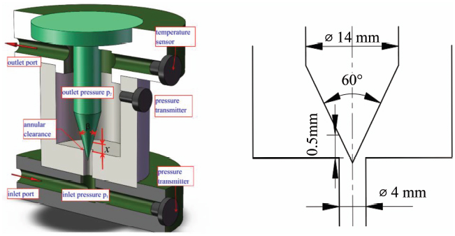
Figure 1 3-D schematic of valve structure.
Table 2 fluid property
| parameter | value |
| liquid type | mineral oil #46 |
| liquid density | 872 kg/m3 |
| liquid dynamic viscosity | 0.042 N s/m2 |
| vapor pressure | 3000 pa |
| vapor density | 0.1 kg/m3 |
| vapor dynamic viscosity | 5.72 N s/m2 |
| temperature | 313K |
| surface tension | 0.03 N/m |
For the sake of reducing computational resources, the flow domain in the simulation only includes a 180° sector, corresponding to only one half of the flow passage of the poppet valve. The sensitivity to spatial discretization is verified in terms of velocity distribution for a cavitating test case. Figure 2 exhibits the calculation results for meshes of different sizes. The time average velocity profile tends to converge for grids with mesh cells above 3.0 million. The employed mesh in the current calculation has approximately 3.5 million cells, as shown in Figure 3. A majority of the grid are structured cell, which conduces to convergence and numerical stability (Ghiji et al., 2016, 2017). Figure 3(b) provides detailed yPlus data for the cells of the first layer neighboring the poppet surface, indicating the criterion of yPlus <1 is generally satisfied.
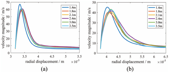
Figure 2 Mesh sensitivity study results. (a) and (b) offer the average velocity profile with outlet pressure of 5 bar and pressure drop of 46 bar, at cross-section of longitudinal position of 2.5mm and 3.5mm, respectively.
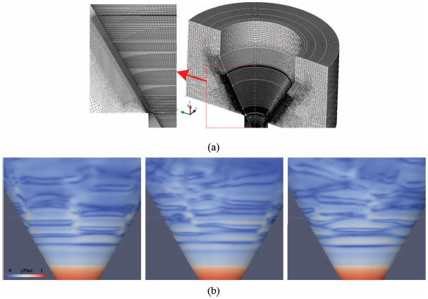
Figure 3 (a) Mesh model used for the current simulation. (b) yPlus magnitude on the poppet surface.
3 Results and Discussion
3.1 Comparison between experiment and simulation
The numerical results are compared with experimental data acquired with the experiment rig schematically sketched in Figure 4. The inlet and outlet pressure are detected with two pressure transmitters (PG1300 from SOKYO with an accuracy of 0.5%). The flow rate is recorded by a flowmeter (YTFL 10 from SOKYO with an accuracy of 0.5 %). The valve house is manufactured with PMMA for a visual observation of the flow structure with a high speed camera (IX 220, with a maximum FPS up to 200,000). The exposure time for the recorded images is 2 microseconds.
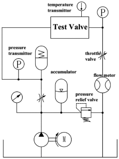
Figure 4 Schematic for the experiment hydraulic circuit.
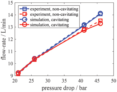
Figure 5 Comparison between predicted and measured flow performance.
(1) Flow performance
Figure 5 exhibits the predicted flow rate and the measured counterpart from experiment. In the non-cavitating case, the outlet pressure is kept at 15 bar to eliminate cavitation for the pressure drop range considered, while a constant outlet pressure of 5 bar in the cavitating case produces a gradually increased cavitation intensity with advances in pressure drop. Favorable comparison between calculation and experiment is achieved with reasonably small discrepancy within 3.5%. In addition, the numerical method also captures the effect of cavitation on flow performance. The detailed correlation between flow performance and flow pattern including cavitation effect has been addressed in a previous study (Yuan et al., 2019b). The general agreement between numerical and experimental methods in terms of flow-rate indicates that the numerical model predicts the overall performance of the cavitating jet quantitatively.
(2) Cavitation morphology
Figure 6 presents the instantaneous cavitation structure from both numerical and experimental methods. In experiment, a rather short exposure time is employed for photography, in order to ensure an instantaneous cavitation morphology. The computational results provide an instantaneous iso-surface of 97% liquid phase content, which, according to a previous study (Egerer et al., 2014), is sufficient to produce a dark spot in the recorded images. Figure 6 provides the gradual increasing cavitation intensity with advances in pressure drop. At a pressure drop of 31bar, cavitation is only observed at quite a downstream region from annular clearance, as shown in Figure 6(a). For non-cavitating region close to the annular clearance, the potential core could be identified from the free shearing layer, which produces an observable trajectory due to vignetting of their refracted light (Egerer et al., 2014). The laminar state of the potential core in the absence of cavitation is distinct from the smooth potential core, which is almost parallel to the poppet surface. As the pressure drop increases, the potential core exhibits a waving tendency at downstream region of the laminar jet column, as shown in Figure 6(b–c). Furthermore, the earliest detectable traces of cavitation are developed with formation of the waving pattern of potential core. As indicated by Figure 6(b), cavitation nucleation is organized as a paired structure. Specifically, the two paired vortexes are distributed respectively at each side of the potential core in a configuration generally consistent with the waving pattern. The paired structure and its consistency with waving potential core is to be addressed in detail in the forthcoming discussion. With increment in pressure drop, cavitation is further enhanced. However, the cavity assumes an intermittent and shedding pattern, rather than a continuous and attached form. In other words, separated paired cavitating bubbles are transported along with the potential core, and undergoes a gradual growth during its motion downstream, as shown in Figure 6(d). The numerical results capture these characteristic dynamics of cavitation morphology qualitatively, confirming its favorable comparison with experimental images. Furthermore, the computation provides more detail of the flow dynamics, which enables a comprehensive analysis on the transitional process, as the following sub-sessions discuss.
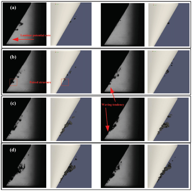
Figure 6 Comparison of instantaneous cavitation structure between experiment and simulation. (Pressure drop is 31, 36, 41 and 46 bar respectively for case a-d, while the outlet pressure is kept constant at 5 bar.).
3.2 Periodic cavitation performance and overall transitional process
Figure 7 displays a complete process of the periodic cavitation performance. One typical period of cavitation can be divided into the following sequential dynamic behaviors, including nucleation of vortex cavitation, consecutive collision of paired cavitating-vortex structure, formation of cloud cavitation, and eventual collapse. Additional indication is provided in Figure 7 for growth of cloud cavitation from inception to final collapse. It is particularly noteworthy that the shedding of cloud cavity first involves a segregation. The large-size cavitation structure is separated into two parts, as shown in Figure 7(ii–iii) and (vii–viii). The downstream cavity is convected by the main flow, and meanwhile collapsed progressively. In comparison, the other cavity moves comparatively slower and experiences an amalgamation with the forthcoming cavitation, which assumes a paired vortex ring. It suggests that generation of cloud cavitation consists of both debris of cloud cavity from last cycle and the incoming cavitating vortex ring.
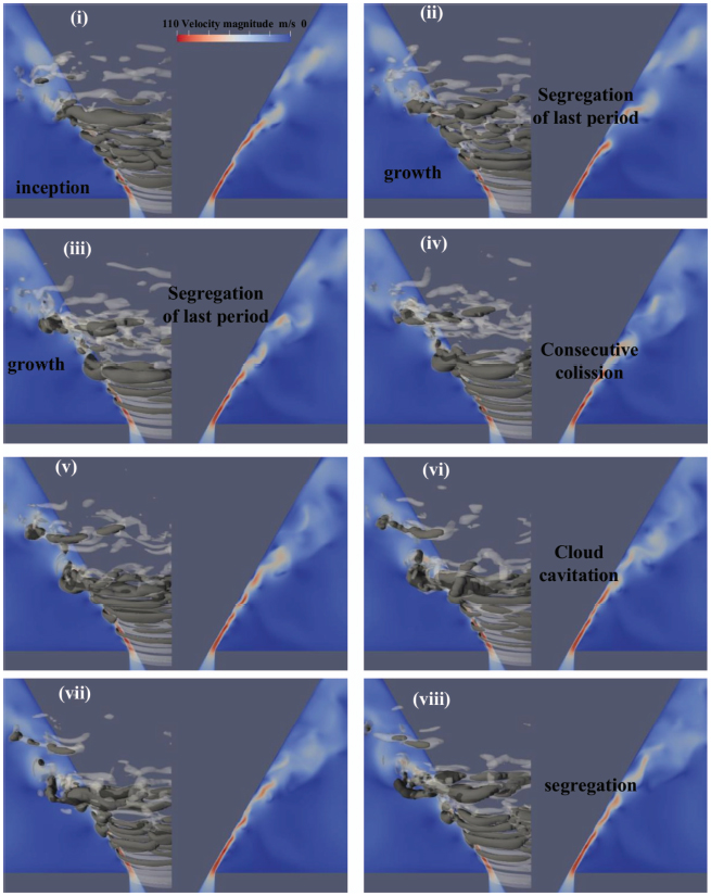
Figure 7 Instantaneous distribution of cavitation and large-scale eddy structure for pressure drop of 46 bar. (Iso-surface with dark color indicates cavitation structure with liquid content of 97%, and the transparent iso-surface with while color indicates large-scale vortical structure with Q=3×10⁹ s−2. Sectional contour for velocity distribution is also included. Images are 3×10⁻⁵ s apart.)
Figure 7 also offers the corresponding time-evolving vortical structure superimposed on cavity structure. There is a striking agreement between the cyclic dynamics of cavitation behavior and development of large-scale turbulent structure. It suggests that vortex factor not only governs cavitation inception, but also plays an interactive role with cavitation during its later evolution after inception. The cavitation-turbulence interaction has been briefly mentioned in a previous study (Yuan et al., 2019b), which, however, is primarily concerned with the fragmentation process of potential core. Figure 7 also includes the sectional contour for velocity distribution at the right half of each image. Figure 7 demonstrates that the large-scale eddy follows a pattern in accord with the periodic process of cavitation. Independent of either the transient cavitation or the fast-evolving large-scale eddy, the velocity distribution at each instant assumes a similar pattern, which clarifies the detailed process of the laminar-turbulent transition. In addition, the evolution of the potential core from initial laminar state to eventual fragmentation coincides well with the development of large-scale eddy. Based on the evolution of the potential core, the transitional flow is divided into several different stages, comprising laminar potential core, waving pattern, roll-up and detachment, and final dissipation, as illustrated in Figure 8.
According to the fluctuation mode measured experimentally, Zaman and Hussain (1980) identify different regions of disturbance growth for the potential core of a submerged circular jet, with great similarity to the present case. The division of the potential core also reveals the correspondence between large-scale eddy and dynamics of potential core. At region close to annular clearance, turbulence intensity is weak, and potential core is organized as a laminar state. Along with the development of large-scale vortical structure, the potential core experiences enhanced disturbance, leading to its final fragmentation into a series of vortexes. It indicates a significant influence of turbulence growth on potential core.

Figure 8 Division of the transitional region according to behavior of jet potential core. (i) laminar state; (ii) waving pattern; (iii) roll-up and detachment; (iv) final dissipation.
Some of the flow dynamics associated with the transitional flow have been reported in a previous work (Yuan et al., 2019b). However, the negligence of three dimensional effect puts a limit on the related analysis, and several critical problems are yet left open, such as the large-scale vortical structure and its interactive role with the potential core. The present simulation allows a re-examination of the transitional process based on a 3-dimensional perspective. Additionally, special concern is paid on the mechanism underlying the flow dynamics, which inevitably involves the cavitation-turbulence interaction. And the forthcoming discussion mainly involves the case for pressure drop of 46 bar unless otherwise specified.
3.3 Laminar jet potential core and paired coherent structure
After the annular clearance, the potential core of jet flow assumes originally a laminar state. However, the earliest perturbation is latent in the smooth potential core. Quite similar to the case of submerged circular jet, the initial instability is generated in the form of Kelvin-Helmhotz vortices, which are primarily attributable to the sudden alteration from wall boundary layer to free shearing boundary layer at the sharp corner of valve seat. As a consequence, a strong velocity gradient towards the ambient quiescent fluid is produced, which is favorable for formation of vortical structure. As Figure 9(a) demonstrates, a small eddy identified by the Q iso-surface is generated adjacent to the sharp corner. It produces a sensible pressure drop at the core of the vortex, as shown in the corresponding pressure distribution. The negative pressure peak could be explained by pressure Poisson equation, which guarantees that the maximum pressure can only appear on the boundary partial region of Q > 0 (Chen et al., 2019). Initially, the Kelvin-Helmholtz instability has the form of a thin layer, owing to the strong shearing effect at the border of potential core. After formation, the Kelvin-Helmholtz instability at the free shearing side experiences a quite evident growth due to the strong shearing effect of potential core, during transportation towards downstream by the main flow as exhibited in Figure 9(b). However, the growth only lasts for a while, and a fairly outstanding evolution occurs to the Kelvin-Helmholtz instability. It is noteworthy that a small eddy is gradually developed at a slight downstream region adjacent to the poppet surface as shown in Figure 9(b). The two counter-rotating vortexes at two sides of the potential core constitute the paired vortex structure, as shown in Figure 9(c). Additionally, the paired structure remains in a stable local equilibrium for quite a distance along its movement downstream. The Kelvin-Helmholtz vortice exhibits significant consistency in the circumferential direction. And during the establishment of paired vortex structure, the circumferential coherence is negligibly affected, as shown in Figure 9(d). Furthermore, the extensive presence and periodic production of the paired structure as illustrated from the time-varying process of large-scale eddy in Figure 9 complies with the concept of coherent structure, quite similar to the more familiar coherent structure in submerged circular jet organized as vortex ring. From the three dimensional view, the coherent structure in the present jet flow appears in the form of paired vortex ring.
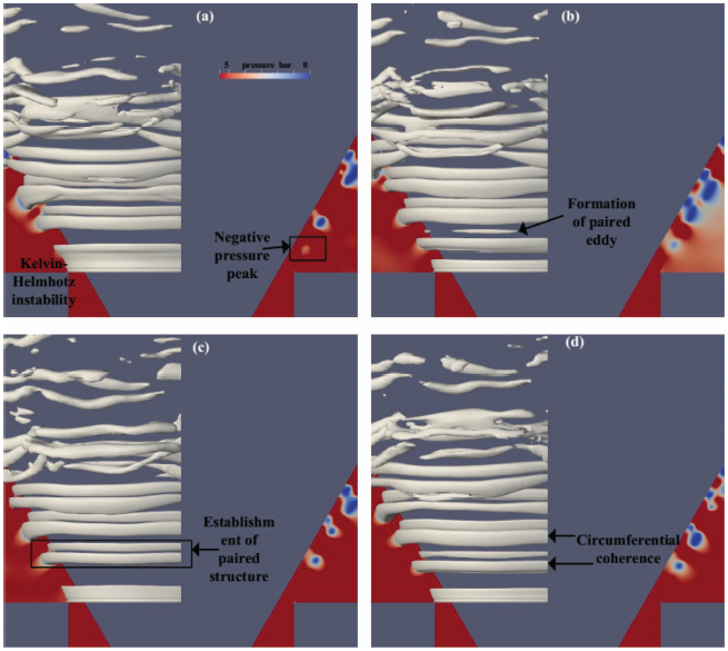
Figure 9 Establishment of paired vortex structure. Vortical structure is visualized by a Q iso-surface of 2×10¹⁰ s−2. (The sectional contour exhibits the pressure distribution, indicating negative pressure peak at vortical core.)
3.4 Waving pattern and interaction between the two paired vortexes
Even though the paired coherent structure remains in a stable state temporarily after its construction, a pronounced interaction is present between the two paired vortexes. To investigate the interaction of the paired vortexes, Kutta-Joukowski theorem is employed, which states that velocity circulation produces a lift to the circulating fluid mass (Long et al., 2018). As a consequence, it plays a significant role in the flow dynamics involved with a turbulent eddy.
The velocity distribution for the near wall region assumes the configuration as illustrated in Figure 10, which gives rise to a corresponding rotary structure. According to the Kutta-Joukowski theorem, a lifting force to the circulating fluid mass in the direction outwards from the wall is produced due to the circulating velocity. As a result, the vortex neighboring to the poppet surface is gradually raised from the poppet surface, as presented in Figure 11. On the contrary, the velocity at the free shear side is organized in an opposite way, as shown in Figure 10. Thus the counter rotating eddy leads to a lift force towards the poppet surface. Consequently, the vortex at the free shearing side moves progressively close to the poppet surface, as presented in Figures 11 and 12.
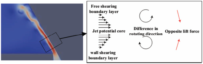
Figure 10 Illustration for the two counter rotating vortexes and the produced opposite lift force.
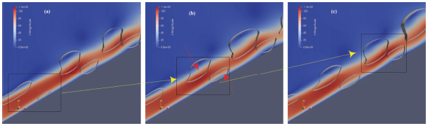
Figure 11 Illustration for formation of waving pattern and the interaction between the two paired vortex rings for pressure drop of 46 bar. (The vortex ring is visualized based on an iso-surface of Q=5×10⁹ s−2. (a) laminar potential core and establishment of paired vortex structure; (b) growth of the paired structure and the opposite lift force for the two vortexes; (c) transition to waving pattern.)
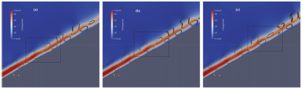
Figure 12 Illustration for formation of waving pattern and the interaction between the two paired vortex rings for pressure drop of 36 bar. (The vortex ring is visualized based on an iso-surface of Q=5×10⁹ s−2. (a) laminar potential core and establishment of paired vortex structure; (b) growth of the paired structure and the opposite lift force for the two vortexes; (c) transition to waving pattern.)
The interaction between the two paired vortexes imposes an appreciable influence on the potential core. Originally the laminar jet column is attached on the poppet surface. On one hand, the vortex at wall side leads to the uprising of the potential core. On the other hand, the vortex at the free shearing side leads to the descending of the potential core. It should be mentioned that the two paired vortexes are not aligned symmetrically with respect to the potential core. The near wall vortex is located slightly downstream. As a consequence, the interaction between the paired vortex structure and the potential core is responsible for the formation of the waving pattern, as shown in Figure 12. The waving pattern, specifically the uprising due to the wall-side vortex, produces local detachment of the potential core. Such flow separation gives rise to further flow instability. However, the paired vortex structure is not yet sufficient to penetrate or split the potential core. Even though the waving pattern of potential core implies a significant enhancement in perturbation, the local equilibrium of the paired structure is to a large extent sustained. As shown in Figure 9, the paired vortex is still organized with general coherence in circumferential direction, implying the sustainment of coherent structure during the formation of waving pattern.
3.5 Cavitation inception
As previous discussion reveals, the vortex factor is the determinant mechanism for cavitation inception. Thus the earliest detectable traces of cavitation come straightforward from intensification in vortex strength of paired coherent structure. The anti-cascade mechanism of vortex pairing contributes to an abrupt and substantial enhancement of vortex strength and leads to a sharp pressure drop (Arndt, 2002; Ran and Katz, 1994). Thus vortex pairing process increases the susceptibility to cavitation. For the underlying jet flow at a modest pressure drop, cavitation inception usually originates from pairing process, as shown in Figure 13. At first, the non-uniform strength of coherent structure leads to the relative displacement between successive paired coherent structures as shown in Figure 13(a–b), similar to the case of circular jet (Hussain, 1986). During the approaching of two neighboring coherent structures, the mergence of the paired structures happens within a small circumferential segment of the coherent structure. And cavitation inception is observed at the merged part, as shown in Figure 13(c). Subsequently, the mergence extends in the circumferential direction, and cavitation follows a similar pattern and occupies the core of the amalgamated new vortex structure, as shown in Figure 13(d–f). And it is of astonishment to confirm that two vortex pairing processes happen almost independently at the two sides of potential core. After the pairing process, the amalgamated new structure still assumes a paired feature. Furthermore, the general coherence is largely preserved during the parallel pairing process, implying the negligible effect on global coherence.
However, the initial identifiable cavitation nucleation under high pressure drop is more frequently produced prior to vortex pairing. Figure 14 presents the detailed process. First, the paired vortex structure is established with the formation of the near wall vortex. Second, the paired coherent structure goes through a gradual growth, leading to an increase in eddy size. Fundamentally, the growth of vortex is essentially due to the strong shearing effect of the jet potential core. Third, cavitation is generated inside the core of vortex ring in the free shearing side, and the inceptive cavitation only assumes a small segment of the coherent structure. Fourth, cavitation extends circumferentially, and occupies the interior of the whole vortex ring. At the same time, cavitation inside the vortex ring near the poppet surface is as well generated. The cavitating vortex structure exhibits a paired feature, and assumes favorable circumferential coherence. Conclusively, inceptive cavitation results directly from gradual enhancement of vortex strength due to the strong shearing effect under high pressure drop.
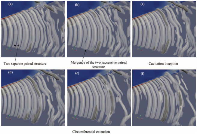
Figure 13 Cavitation inception through vortex pairing. (Pressure drop is 31 bar.)
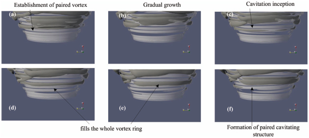
Figure 14 Cavitation inception directly due to vortex growth. (Pressure drop is 46 bar.)
There is less surprise in the coincidence of cavitation and vortical structure, since vortex factor is the main contributor. In fact, there are also solid evidences for involvement of vortex factor even in attached cavitation (Katz, 1984). And accordingly, the inceptive cavitation assumes not only paired structure, but also favorable circumferential coherence. Even though the near wall vortex leads to flow separation, which is susceptible to cavitation, the free-shearing-side vortex is the dominant role in paired structure. And slightly later, cavitation is triggered inside the near-wall vortex, and produces the paired cavity with combination of the vortex ring at the free shearing side. The present 3-D numerical results demonstrate that the new cavitating structure exhibits sensible coherence, which is in agreement with experimental observations from Washio et al. (2010), and beyond the ability of a previous 2-D study (Yuan et al., 2019a).
3.6 Second pairing and loss of coherence
At beginning, the consecutive coherent structures remain at a subtle local equilibrium. The non-uniformity in their subsequent development leads to disturbance to the local equilibrium, and further to a second pairing between the successive paired structures. However, the non-uniform development of the coherent structure is not only confined in the longitudinal direction, which generates the pairing between neighboring paired structures. But non-uniformity is also present in the circumferential direction and becomes evident after cavitation inception.
Figure 15 exhibits the illustration for the circumferential instability. In comparison to the longitudinal disturbance, the instability in the circumferential direction produces disturbance to the coherence of vortical structure, which subsequently results in asymmetry in sectional size of the paired vortex ring. The circumferential non-uniformity becomes appreciable at cavitation inception, which follows an unsynchronized pattern and lasts for a while. Cavitating structure first appears inside the part of vortex ring with strong vortical intensity, while those weak part remains temporarily fully wetted, as shown in Figure 15(a). For those segments with stronger vortex strength, the longitudinal velocity of the potential core is impeded due to the fierce interaction of the two paired vortexes, as explained in previous study (Yuan et al., 2019a). Thus the stronger vortex segment is inclined to a pairing process with the forthcoming paired coherent structure from upstream, as shown in Figure 15(c). For those segments with weaker vortex strength, the longitudinal velocity of the potential core is less affected. Thus the weaker vortex segment moves faster and tends to induce a pairing process with a downstream paired structure, as shown in Figure 15(b). The disparity in pairing along the circumferential direction causes a remarkable influence on the overall coherence. As Figure 15(d) illustrates, the coherent structure is split into several segments, which are still parallel to each other. It indicates the loss of general coherence, even though these parallel segments preserve sensible order within their length.
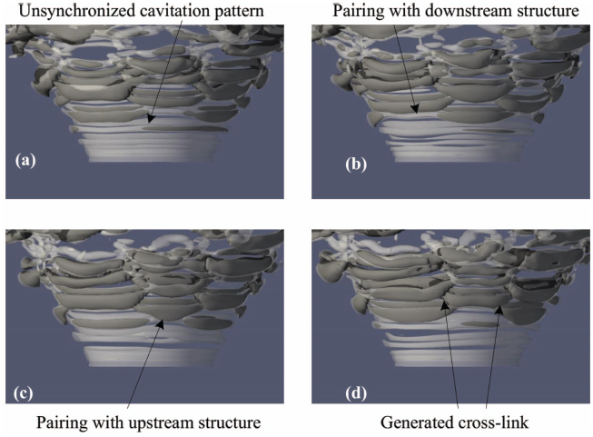
Figure 15 Formation process of cross-link structure through vortex pairing.
However, it should be mentioned that the amalgamated cross-link structure still preserves a paired feature. Furthermore, the paired vortex rings are no longer separately aligned, but cross-linked with neighboring ones. An interesting phenomenon associated with the cross-link between successive coherent structures is the fish-scale distribution of pressure on the poppet surface, as shown in Figure 16. For submerged circular jet, the destruction of coherent structure is ascribed to the development of streamwise vortices (Hussain, 1986; Zaman and Hussain, 1980). During the formation of asymmetry in vortical structure, by contrast, there is no distinct traces of streamwise vortices in the jet flow under study. The streamwise vorticity is largely due to the interlace between the parallel-aligned segments. The direction of rotation has a component parallel to the axis. An overall distribution of the streamwise vorticity is given by Figure 17, which presents the time-average ratio of circumferential vorticity against total vorticity. Adjacent to the annular clearance, the streamwise vorticity is negligibly small. At region of cross-link structure, the ratio is still above 90%, indicating the dominance of coherent vorticity. It is thus reasonable to speculate the marginal effect of streamwise vortices on loss of coherence. Another important conclusion could be drawn that destruction of the global coherence is due to non-uniform instability along the circumferential direction rather than growth of streamwise vortical structure.
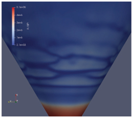
Figure 16 Fish scale distribution of pressure on poppet surface.
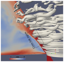
Figure 17 Distribution for ratio of circumferential vorticity against total vorticity.
3.7 Disruption of paired structure and consecutive collision
The development of asymmetry leads to cross-link between successive coherent structures and the loss of circumferential coherence. However, the paired feature yet survives. Noticeably, the cross-link structure assumes such a configuration that the circumferential coherent segments exhibit higher strength and are connected by the weak link. The weak link becomes less distinct due to gradual dissipation or further pairing. And the vortex ring is split into separate segments. These segments preserve appreciable coherence within their circumferential length. Their roughly parallel alignment to each other with varying longitudinal displacement produces a staggered distribution, as shown in Figure 18(a–b). In addition, the vortex strength for these separate segments is of great difference. Consequently, the separate segments tend to trigger further pairing with the longitudinally neighboring ones. Such a process, termed as third pairing (Yuan et al., 2019b), involves a series of cavitating vortex amalgamation. As Figure 18(c–e) illustrates, an array of paired structure approaches the leading cavitating paired vortex in turn, consequently producing a consecutive collision. The consecutive collision occurs rather aggressively and leads to disruption of the paired structure, as shown in Figure 18(f). Besides, vortex cluster consisting of lots of vortical filaments is generated as a result of the amalgamation of cavitating vortexes. On one hand, the cloud cavitation rolls up at trailing edge, and segregates the potential core. On the other hand, breakdown of paired structure generates numerous small-size turbulence, and leads to generation of incoherent turbulence. The process confirms that streamwise vortices originate from disruption of the paired structure through a violent pairing process. It explains the decreased ratio at wake region in Figure 17.
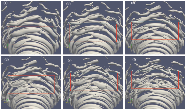
Figure 18 Process of consecutive pairing.
4 Conclusion
In the present study, a numerical simulation is performed to investigate the transitional process for cavitating jet inside a poppet valve with a poppet angle of 60° and openness amount of 0.5 mm. Cavitation and laminar-turbulent transition are intimately correlated. The associated flow dynamics and governing mechanism are addressed. The following important conclusions are drawn, contributing to an improved view of the internal flow.
- For the considered case of outlet pressure of 5 bar, scattered cavitation is produced within the shearing layer of the potential core at pressure drop of 31 bar and 36 bar, while cloud cavitation is developed with breakdown of the potential core at pressure drop over 41 bar. The occurrence of cavitation is responsible for deviation in flow rate up to approximately 7% at pressure drop of 46 bar, compared to the non-cavitating case.
- According to the periodic behavior of the cavitating jet at pressure drop of 46 bar, generation of cloud cavitation involves both debris of cloud cavity from last cycle and the incoming cavitating vortex ring.
- Waving pattern of the potential core is ascribed to the lifting force on the two paired vortex. With careful examination of the inceptive process, the vortex cavitation is produced in different ways depending on the pressure drop. In the case of 31 bar pressure drop, cavitation is formed as a result of vortex pairing. At high pressure drop of 46 bar, cavitation inception is caused frequently merely by the growth of the vortex ring.
- Longitudinal and circumferential instability of the coherent structure lead to unsynchronized pairing, and produce the cross-link structure. Circumferential vorticity at region of cross-link structure remains dominant with a ratio of 90% against total vorticity for the case of 46 bar pressure drop, while the streamwise vortices mainly result from consecutive pairing.
The future work will be concerned about the viscous effect on vortex cavitation and a comprehensive study on cavitation effect, including the flow dynamics associated with choked flow, the influence of cavitation on vortex evolution and the alteration in breakdown process of potential core.
Acknowledgement
We are grateful for financial support from National Natural Science Foundation of China (No. 51975511), Fundamental and Application Fundamental Research Funds of Guangdong Province (No. 2019A1515110844), Youth Innovative Program for Universities in Guangdong Province (No. 2019KQNCX177), and Fundamental Research Funds for the Central Universities (No. N170303010).
Disclosure Statement
No potential conflict of interest was reported by the authors.
References
Antoniak, P., & Stryczek, J., 2018. Visualization study of the flow processes and phenomena in the external gear pump. Archives of Civil and Mechanical Engineering, 18(4), 1103–1115.
Arndt, R. E., 2002. Cavitation in vortical flows. Annual review of fluid mechanics, 34(1), 143–175.
Chen, Y., Li, J., Gong, Z., Chen, X., & Lu, C., 2019. Large eddy simulation and investigation on the laminar-turbulent transition and turbulence-cavitation interaction in the cavitating flow around hydrofoil. International Journal of Multiphase Flow, to be published.
Demirdžić, I., Lilek, Ž., & Perić, M., 1993. A collocated finite volume method for predicting flows at all speeds. International Journal for Numerical Methods in Fluids, 16(12), 1029–1050.
De Villiers, E., Gosman, A. D., & Weller, H. G., 2004. Large eddy simulation of primary diesel spray atomization (No. 2004-01-0100). SAE Technical Paper.
Egerer, C. P., Hickel, S., Schmidt, S. J., & Adams, N. A., 2014. Large-eddy simulation of turbulent cavitating flow in a micro channel. Physics of Fluids, 26(8), 085102.
Furukawa, A., & Tanaka, H., 2006. Violation of the incompressibility of liquid by simple shear flow. Nature, 443(7110), 434–438.
Ghahramani, E., Arabnejad, M. H., & Bensow, R. E., 2019. A comparative study between numerical methods in simulation of cavitating bubbles. International Journal of Multiphase Flow, 111, 339–359. Ghiji, M., Goldsworthy, L., Brandner, P. A., Garaniya, V., & Hield, P., 2016. Numerical and experimental investigation of early stage diesel sprays. Fuel, 175, 274–286.
Ghiji, M., Goldsworthy, L., Brandner, P. A., Garaniya, V., & Hield, P., 2017. Analysis of diesel spray dynamics using a compressible Eulerian/VOF/LES model and microscopic shadowgraphy. Fuel, 188, 352–366.
Han, M., Liu, Y., Wu, D., Zhao, X., & Tan, H., 2017. A numerical investigation in characteristics of flow force under cavitation state inside the water hydraulic poppet valves. International Journal of Heat and Mass Transfer, 111, 1–16.
Hussain, A. F., 1986. Coherent structures and turbulence. Journal of Fluid Mechanics, 173, 303–356.
Katz, J., 1984. Cavitation phenomena within regions of flow separation. Journal of Fluid Mechanics, 140, 397–436.
Karrholm, F. P., Weller, H., & Nordin, N., 2007. Modelling injector flow including cavitation effects for diesel applications. In ASME/JSME 2007 5th joint fluids engineering conference, pp. 465–474.
Koukouvinis, P., Naseri, H., & Gavaises, M., 2017. Performance of turbulence and cavitation models in prediction of incipient and developed cavitation. International Journal of Engine Research, 18(4), 333–350.
Liang, J., Luo, X., Liu, Y., Li, X., & Shi, T., 2016. A numerical investigation in effects of inlet pressure fluctuations on the flow and cavitation characteristics inside water hydraulic poppet valves. International Journal of Heat and Mass Transfer, 103, 684–700.
Liu, Y. S., Huang, Y., & Li, Z. Y., 2002. Experimental investigation of flow and cavitation characteristics of a two-step throttle in water hydraulic valves. Proceedings of the Institution of Mechanical Engineers, Part A: Journal of Power and Energy, 216(1), 105–111.
Long, X., Cheng, H., Ji, B., Arndt, R. E., & Peng, X., 2018. Large eddy simulation and Euler–Lagrangian coupling investigation of the transient cavitating turbulent flow around a twisted hydrofoil. International Journal of Multiphase Flow, 100, 41–56.
Lu, L., Zou, J., Fu, X., Ruan, X. D., Du, X. W., Ryu, S., & Ochiai, M., 2009. Cavitating flow in non-circular opening spool valves with U-grooves. Proceedings of the Institution of Mechanical Engineers, Part C: Journal of Mechanical Engineering Science, 223(10), 2297–2307.
Nie, S., Huang, G., Li, Y., Yang, Y., & Zhu, Y., 2006. Research on low cavitation in water hydraulic two-stage throttle poppet valve. Proceedings of the Institution of Mechanical Engineers, Part E: Journal of Process Mechanical Engineering, 220(3), 167–179.
Oshima, S., & Ichikawa, T., 1985. Cavitation Phenomena and Performance of Oil Hydraulic Poppet Valve: 1st report mechanism of generation of cavitation and flow performance. Bulletin of JSME, 28(244), 2264–2271.
Oshima, S., & Ichikawa, T., 1985. Cavitation Phenomena and Performance of Oil Hydraulic Poppet Valve: 2nd Report, Influence of the Chamfer Length of the Seat and the Flow Performance. Bulletin of JSME, 28(244), 2272–2279.
Oshima, S., & Ichikawa, T., 1986. Cavitation Phenomena and Performance of Oil Hydraulic Poppet Valve: 3rd report, influence of the poppet angle and oil temperature on the flow performance. Bulletin of JSME, 29(249), 743–750.
Oshima, S., Leino, T., Linjama, M., Koskinen, K. T., & Vilenius, M. J., 2001. Effect of cavitation in water hydraulic poppet valves. International journal of fluid power, 2(3), 05–13.
Ran, B., & Katz, J., 1994. Pressure fluctuations and their effect on cavitation inception within water jets. Journal of Fluid Mechanics, 262, 223–263.
Schmidt, D. P., Rutland, C. J., & Corradini, M. L., 1999. A fully compressible, two-dimensional model of small, high-speed, cavitating nozzles. Atomization and sprays, 9(3).
Schmidt, D. P., & Corradini, M. L., 2001. The internal flow of diesel fuel injector nozzles: a review. International Journal of Engine Research, 2(1), 1–22.
Schnerr, G. H., & Sauer, J., 2001. Physical and numerical modeling of unsteady cavitation dynamics. In: Fourth international conference on multiphase flow.
Ubbink, O., & Issa, R. I., 1999. A method for capturing sharp fluid interfaces on arbitrary meshes. Journal of Computational Physics, 153(1), 26–50.
Washio, S., Kikui, S., & Takahashi, S., 2010. Nucleation and subsequent cavitation in a hydraulic oil poppet valve. Proceedings of the institution of mechanical engineers, part C: journal of mechanical engineering science, 224(4), 947–958.
Yi, D., Lu, L., Zou, J., & Fu, X., 2015. Interactions between poppet vibration and cavitation in relief valve. Proceedings of the Institution of Mechanical Engineers, Part C: Journal of Mechanical Engineering Science, 229(8), 1447–1461.
Yinshui, L., Yousheng, Y., & Zhuangyun, L., 2006. Research on the flow and cavitation characteristics of multi-stage throttle in water-hydraulics. Proceedings of the Institution of Mechanical Engineers, Part E: Journal of Process Mechanical Engineering, 220(2), 99–108.
Yu, H., Goldsworthy, L., Brandner, P. A., & Garaniya, V., 2017. Development of a compressible multiphase cavitation approach for diesel spray modelling. Applied Mathematical Modelling, 45, 705–727.
Yuan, C., Song, J., & Liu, M., 2019a. Investigation of flow dynamics and governing mechanism of choked flow for cavitating jet in a poppet valve. International Journal of Heat and Mass Transfer, 129, 113–131.
Yuan, C., Song, J., & Liu, M., 2019b. Coherent structure of paired vortex and transition in flow pattern in cavitating jet through a poppet valve. International Journal of Mechanical Sciences, 152, 19–33.
Yuan, C., Song, J., & Liu, M., 2019c. Comparison of compressible and incompressible numerical methods in simulation of a cavitating jet through a poppet valve. Engineering Applications of Computational Fluid Mechanics, 13(1), 67–90.
Zaman, K. B. M. Q., & Hussain, A. K. M. F., 1980. Vortex pairing in a circular jet under controlled excitation. Part 1. General jet response. Journal of fluid mechanics, 101(3), 449–491.
Zhang, B., Ma, J., Hong, H., Yang, H., & Fang, Y., 2017. Analysis of the flow dynamics characteristics of an axial piston pump based on the computational fluid dynamics method. Engineering Applications of Computational Fluid Mechanics, 11(1), 86–95.
Zhang, S., & Li, S., 2015. Cavity shedding dynamics in a flapper–nozzle pilot stage of an electro-hydraulic servo-valve: Experiments and numerical study. Energy conversion and management, 100, 370–379.
Zhou, J., Vacca, A., & Casoli, P., 2014. A novel approach for predicting the operation of external gear pumps under cavitating conditions. Simulation Modelling Practice and Theory, 45, 35–49.
Biographies
Cong Yuan received his Ph.D. degree in mechanical engineering from Northeastern University, Shenyang, China, in 2019. He is currently a lecture with the school of Mechanical and Automotive Engineering, Zhaoqing University, China. His main research interests include cavitation in hydraulic valves, cavitating jet and cavitation erosion.
Yan Cai received his B.S. and Ph.D. degree in Mechanical Engineering from Northeastern University, China in 2012 and 2017, respectively. He was once a Ph.D. visiting scholar at the University of Manitoba, Canada. Dr. Cai is now a lecturer with the School of Mechanical Engineering and Automation at Northeastern University, China. His research interests include robust and nonlinear control of hydrostatic actuation, bilateral control, and mobile robots.
Shiqi Liu is a Ph.D. student at Northeastern University. He received his Master’s degree in mechanical engineering in 2018. He is currently completing a Ph.D. in mechanical and electrical engineering at Northeastern University. His research interests include fluid optimization simulation. Optimization of heat exchanger network for cooling water system.

Zunling Du received the B. E. degree in agricultural architectural environment and energy engineering from Shenyang Agricultural University in 2008, and the M. S. degree in mechanical design and theory in Northeast University in 2010, he is currently a research associate in Zhaoqing University, China. His main interests include hydraulic systems design and mechanical reliability design.
International Journal of Fluid Power, Vol. 21_1, 27–58.
doi: 10.13052/ijfp1439-9776.2112
© 2020 River Publishers