Pulsation Simulation and Energy Consumption Analysis of Series Pump Valve Cooperative Control Hydraulic System
Ke-chang Zhang and Jin-yan Shi*
Hunan Railway Professional Technology College, ZhuZhou 412001, China
E-mail: shijinyan2008@126.com
*Corresponding Author
Received 27 July 2021; Accepted 17 August 2021; Publication 06 September 2021
Abstract
In order to reduce the pulsation and the energy consumption of the hydraulic system, the series pump and valve cooperative control hydraulic system is designed, and the pulsation simulation and energy consumption analysis of it is carried out. Firstly, the working principle of series pump valve co control system is studied. Secondly, the mathematical model of series pump valve cooperation control system is established. And then the Controller of series pump valve cooperation control system is designed. Finally, the simulation analysis of the proposed hydraulic system is carried out, and results show that the proposed system has high stability and low energy consumption.
Keywords: Series pump and valve cooperative control, hydraulic system, pulsation simulation, energy consumption.
1 Introduction
The electrical hydraulic servo valve control system has some advantages, such as strong load capacity, big load stiffness, large power density, fast response and high controlling precision, therefore it has irreplaceable position in movement controlling field, it has been applied in many fields, such as aerospace, weapon, machine tool, and ship. The servo direct drive pump control system has been widely applied for its high efficiency, wide range of regulating speed and good stability. The servo valve controlling system has many advantages mentioned above, but it has also many disadvantages, such as low controlling precision and low response. In order to combine the advantages of valve controlling system and pump controlling system, the valve controlling system and direct drive system can be combined to form a novel cooperative control hydraulic system.
In the normal series pump vale cooperative controlling system, the pump controlling circuit and valve controlling circuit are combine in series. The basic theory of it is to match the output flow rate of pump station system and load flow through changing rotational speed of motor or displacement of pump, and then the overflow loss of the relief valve is reduced, the energy utilization efficiency can be improved. Based on the series flow control valve can regulate the load flow precisely and the system bandwidth can be increase.
Zhicheng Xu et al. proposed a hydraulic system combing valve-pump combined controlled hydraulic system with multiple accumulators, and the energy efficiency of the proposed system is improved [1]. Gong Guofang et al. proposed valve and pump compounded pressure control system for the hydro viscous clutch to enlarge the working pressure range, and the pressure control range can be increased [2]. Bing Xu et al. Designed a three level controller to improve the energy efficiency, through coordinate control of the pump and valves, the meter in valve opens maximally and the pressure losses across the valves is minimized [3]. Litong Lyu et al. proposed a parallel connected pump valve coordinated system, and carriedout further improvements to control design of it, experiment results showed that the proposed sysetm has better tracking performance and can improve the energy efficiency [4]. Prabhakar Kushwaha et al. compared the dynamic performances of the valve control system, the pump control system and prime mover control system for a wide range of operating conditions. Analysis results showed that valve controlling system is more sensitive than other systems, and the pump control system has less overshoot [5]. Du Jia et al. proposed a pump-valve coordinated composite control hydraulic system. Experiment results showed that the proposed system can reduce the power consumption greatly [6]. Liu Hua et al. proposed an energy saving system to coordinate control the pump speed and independent metering, experiment results showed that the proposed system could improved pressure control accuracy. References [7]. Wang yunpeng et al. designed a pump and valve coordinated control electro-hydrostatic actuator, and the pump control and valve control models are constructed. The advantages of the proposed system are verified through experiment analysis [8]. Ying yizhi et al. proposed the intelligent prestressed tensioning equipment based on cooperative control technology of servo pump valve. The proposed system can control oil pump stably [9]. Zhao Shuli proposed an industrial intelligent pump valve coordinate control platform based on internet of things technology, the proposed system could realize collaborative operation between the initial inusrial level intelligent pump and valve control systems that independently deal with specific functions, and effectively integrates the existing related application business and new application business into one [10].
The dead time and nonlinear friction characteristics of hydraulic components make the electro-hydraulic servo control system have significant nonlinear characteristics and uncertain parameters. It is necessary to improve its control performance through control technology. The main controlling algorithms conclude PID controlling algorithm, self adaption controlling algorithm, sliding mode variable structure control algorithm and robustness controlling algorithm. PID control has the advantages of simple principle, easy to understand, reliable operation and so on. Moreover, it does not need an accurate system model, and the parameter adjustment is simple. It is widely used in various engineering applications. However, the traditional PID controller is a simple linear superposition of proportional term, integral term and differential term, and the parameters remain unchanged in the control process, so it is difficult to solve the contradiction between the rapid response and stability of the system, and the control performance of PID can not be guaranteed in the system with variable parameters. The parameters of the hydraulic system are variable and have significant nonlinearity, so the traditional PID control can not achieve good control effect.
The adaptive control algorithm can change the structure or parameters of the controller by identifying the model parameters of the time-varying system, so that the system can have the characteristics of high control accuracy and strong anti-interference at the same time, so it is widely used in the electro-hydraulic servo system with significant time-varying characteristics. In practical application, adaptive control has some shortcomings, such as the identification process of system time-varying parameters is complex, the amount of calculation is large, and it is difficult to meet the requirements of real-time control for the system with fast response speed.
Because the design of sliding mode is independent of disturbance and plant parameters, the variable structure control has the advantages of insensitive to disturbance and parameter changes, fast response, no need to identify system parameters online, and simple physical implementation. The disadvantage of sliding mode variable structure control is that when the state trajectory reaches the sliding surface, it will travel back and forth on both sides of the sliding surface, resulting in chattering, and can’t strictly slide along the sliding surface towards the equilibrium point.
Robust control is a kind of control algorithm which can adapt to system model uncertainties and system micro perturbations. It can still ensure the good performance of the system when dealing with system perturbations. The robust controller is designed under the perturbation boundary conditions of the system. The designed robust controller can ensure the normal operation of all cases within the perturbation boundary of the system, and ensure good control performance.
Working Principle of Series Pump Valve Co Control System
According to the function, the series pump valve co control system can be divided into two parts: pump control system and valve control system. The function of the pump control part is to adjust the output flow of the oil source according to certain rules on the premise of meeting the demand of the system load flow, so as to reduce the overflow loss of the system and improve the efficiency of the system.
Under the ideal condition, when the output flow of oil source is equal to the load flow, the overflow flow of the system is zero, and the flow efficiency of the system is the maximum. However, in the actual hydraulic system, there is a certain amount of leakage in the hydraulic pump and cylinder. In order to maintain the pressure stability of the system, there must be a certain overflow flow at the relief valve, so the oil source flow is usually greater than the load flow. The valve control part of the series pump valve co control system is actually a typical valve control system. The only difference is the oil source. There are inevitably a lot of overflow loss and throttling loss in valve control system. In the series pump valve coordinated control system, the output flow of the pump control part is adjustable, which is equivalent to providing a load sensitive constant pressure oil source for the valve control part. Therefore, the series pump valve coordinated control system can also have the excellent dynamic performance and control precision of the traditional valve control system.
According to the different ways of adjusting the output flow of oil source in the pump control part of the system, the series pump valve coordinated control system can be divided into the following three structural forms:
(1) AC servo motor one-way quantitative pump: the scheme adjusts the output flow of the oil source by changing the speed of the hydraulic pump. Its advantages are simple structure, small space occupation, high reliability and low cost; The disadvantages are large moment of inertia of motor and hydraulic pump, low frequency response and poor dynamic characteristics of the system.
(2) Constant speed motor servo variable pump: the scheme adjusts the output flow of oil source by changing the displacement of variable pump. At present, servo variable displacement pump is usually composed of swash plate piston pump and servo variable displacement mechanism. Servo variable mechanism is actually a valve controlled cylinder system. The advantages of this scheme are mature technology and good dynamic characteristics of the system. The disadvantages are that the swash plate of the servo variable displacement pump needs to be driven by the valve controlled cylinder. The system needs a set of auxiliary oil source device. There is a waste of energy in the operation of the valve controlled cylinder variable mechanism. Moreover, the cost of the servo variable displacement pump is expensive and the system structure is more complex.
(3) AC servo motor servo variable pump: this scheme can change the speed and displacement of the hydraulic pump at the same time, so that the dynamic characteristics of the system can be greatly improved, and the reliability of the system is significantly improved due to the dual redundancy control. But on the other hand, this method also increases the complexity of the system structure and the difficulty of the control strategy design. After decades of development, AC servo motor and frequency control technology have greatly improved in dynamic performance and control accuracy.
In this research, the structural diagram of series pump valve coordination system is shown in Figure 1. From the perspective of functional division, the independent control subsystem of import and export realizes the compound control of the position and pressure of the actuator by controlling the spool displacement of the two servo valves, so as to reduce the energy consumption and improve the stability of the system; The pump control subsystem provides flow and pressure for the system by controlling the speed of the pump.
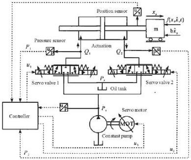
Figure 1 Diagram of series pump valve coordinated controlling system.
Mathematical Model of Series Pump Valve Co Control System
The balance equation of actuator output force and load force is expressed by
| (1) |
where represents the load mass, represents the load speed, represents the load location, and are the pressure of two chambers of actuator, and are the areas of two chambers of actuator, represents the viscous damping coefficient of piston and load, is function of unmodeled force and external interference force.
The servo valve dynamic is simplified to proportional link, which is expressed by
| (2) |
where denotes the spool displacement of servo valve, denotes the input signal of servo valve, denotes the gain of servo valve.
The flow equations of two chambers of servo valve are expressed by
| (3) | ||
| (4) |
where , , represents the discharge coefficient, represents the area gradient o servo valve, denotes the density of hydraulic oil, represents the flow of two chambers of hydraulic tank, represents the supplying oil pressure, represents the returning oil pressure.
The dynamic equations of two chambers of actuator are expressed by
| (5) | ||
| (6) |
where and are the volume of two chambers of hydraulic tank, represents the volume elastic module of oil.
Suppose that the frequency response of motor is higher than working frequency of actuator, the dynamics of motor can be simplified as portion part, which is expressed by
| (7) |
where represents the gain of motor rotational speed, denotes the input signal of servo motor.
The flow of servo valve is expressed by
| (8) |
Suppose the frequency response of pump control subsystem is higher than working frequency of actuator, the mechanical dynamics in pump is ignored, and the outlet pressure dynamics of pump is expressed by
| (9) |
where represents the volume of hydraulic pump, represents the discharge of constant pump.
The pump valve coordinated control system is a multiple input multiple output system with strong coupling; The specific performance is: there is a coupling relationship between the output pressure of the pump and the flow rate of the flow servo valve, and the pressure of the two cavities of the pump is also coupled with the piston speed.
Controlling Algorithm of Series Pump Valve Co Control System
Suppose that uncertain nonlinearity can be decomposed into slowly time-varying parts and fast time-varying parts . In addition, the boundary between and is definite, and the following expresses can be obtained.
| (10) | |
| (11) | |
| (12) |
where and are positive real number determined.
Next, the system is divided into motion dynamics and pressure dynamics, and the controller is designed in two steps.
(1) Design of controller 1
The expected trajectory is defined by , and the tracking error is defined by , and the switching surface is defined by , where is the positive feedback gain, therefore the convergence is equivalent to convergence, and the semipositive definite Lyapunov function is expressed by
| (13) |
where is the positive weight factor, the derivative of with respect to time is expressed by
| (14) |
The output force of driving cylinder is defined by , which is used as virtual controlling input of expression (14), and the controlling functions are expressed by
| (15) |
where denotes the expected controlling force, which concludes and . compensates the modeling forces such as Coulomb friction force, gravity force and load force in the system, and introduces the compensation of expected inertial force and expected viscous resistance into the forward channel as the model compensation term. is a robust control item, which is expressed by
| (16) |
where is the nominal stabilization part, which is linear feedback control, including proportional feedback and differential feedback of position error, is designed to deal with uncertainty, nonlinearity and model error. It is a smooth function.
(2) Design of controller 2
Let and represent the expected pressures of the two cavities of the driving cylinder respectively. In order to make converge, they must satisfy the constraint condition:
| (17) |
When the leakage is ignored and the hydraulic cylinder works at a steady working point, the flow rate should meet the requirements
| (18) |
The following expression can be deduced:
| (19) |
where
represents the pressure of source.
Obviously, if and converge to and at the same time, can realize the pairing , so converges. In order to deduce the control law that makes the pressure of the two cavities of the driving cylinder follow the desired pressure, the Lyapunov function is constructed based on the theory of hydraulic passivity.
The semi definite Lyapunov function is constructed by using the pressure error energy storage function of the two cavities of the driving cylinde1r, and the control law is derived by
| (20) |
where , , represents the positive weight factor.
Case Study
This research uses AMESim and MATLAB co simulation platform for simulation analysis. The hydraulic model is built in AMESim and the control strategy is implemented in MATLAB. The energy efficiency of the system is compared with the energy-saving load sensing system; In the simulation, the hydraulic cylinder drives the load to rise and fall vertically. When the load rises, the gravity hinders the movement of the hydraulic cylinder; When the load drops, the gravity assisted hydraulic cylinder moves beyond the retraction condition.
The position tracking command is , the differential pressure command is 15 bar, and the right chamber pressure command is 20 bar. The basic parameters of the pump and valve coordinated control system are listed in Table 1.
Table 1 Parameters of pump and valve coordinated control system
| Parameter | Value |
| Actuator stroke/m | 0.5 |
| Area of left chamber of actuator/m | |
| Area of right chamber of actuator/m | |
| Load mass/kg | 125 |
| Rated pressure of servo valve/bar | 40 |
| Rated flow of servo valve/L/min | 42 |
| Constant pump discharge/cc/rec | 15 |
| Rated current of servo valve/mA | 38 |
| Volume elastic module of oil/bar | 7000 |
The displacement curves are shown in Figure 2. As can be seen from Figure 2, the displacement has a certain lag, but maintains good following characteristics, there is no overshoot in the reduction stage, and the control accuracy is up to 0.5 mm.
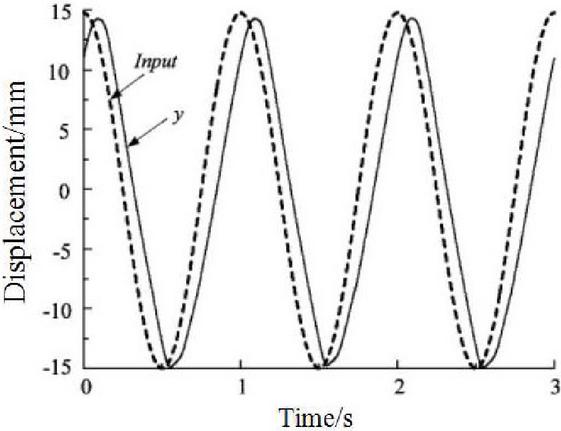
Figure 2 Displacement curve of pump and valve coordinated control system.
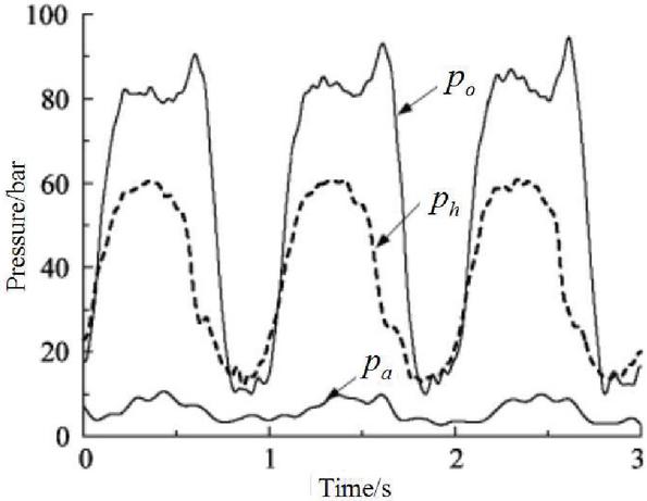
Figure 3 Pressure curve of pump and valve coordinated control system.
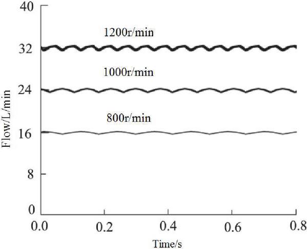
Figure 4 Flow pulsation of series pump and valve coordinated controlled hydraulic system under 25 Bar.
Figure 3 shows the pressure curve of pump and valve coordinated control system, in which is the main cylinder pressure, is the return cylinder pressure, and is the pump port pressure. It can be seen from figure 3 that the pressure at the pump port varies with the load pressure of the main cylinder and return cylinder. However, the pressure change rate is slow due to the response speed of the frequency converter motor. The pressure difference between the pump port and return cylinder is basically 20 bar in return stage, and the response time is about 0.15 s. When the return stroke is switched to depression, the pump port pressure shall change with the master cylinder pressure. At the moment of switching, the difference between the pump port and the master cylinder pressure is greater than the set value, and the given signal of the motor is set to zero. However, due to the inertia of the motor, the quantitative pump still inputs flow to the system, resulting in a spike in the pump port pressure. With the decrease of the input flow of the rear pump and the opening of the inlet valve of the master cylinder, the pump port pressure decreases.
Figure 4 shows the flow pulsation of series pump and valve coordinated controlled hydraulic system under load of 25 Bar, and Table 2 lists the analysis results of flow pulsation distribution of single pump and series pump and valve coordinated controlled hydraulic system. indicates the proportion of the output flow fluctuation value to the average flow, which reflects the fluctuation of flow fluctuation to a certain extent. The smaller the value, the better the stability.
Table 2 Flow pulsation distribution of single pump and series pump controlled hydraulic systems under different pressures
| Load/Bar | Minimum Value/L/min | Maximum/L/min | /% |
| 25 | 31.3 | 31.6 | 2.2 |
| 30 | 33.5 | 33.7 | 2.3 |
| 35 | 34.7 | 34.9 | 2.5 |
The load of the system increases from 25 Bar to 35 Bar, and the difference of the pump output flow of the single pump control hydraulic system also increases, forming a larger flow pulsation range. When the load increases, the flow pulsation range of the series pump control hydraulic system also decreases. This is because increasing the load will increase the burden of the hydraulic system, reduce the operation stability, and then show the increase of flow fluctuation. It is noted that the flow pulsation of the series pump controlled hydraulic system does not change significantly with the increase of load, which shows that the design of the system has good stability.
The energy consumption of the pump and valve coordinated control hydraulic system is carried out, and the analysis results are listed in Table 3. As seen from Table 3, in the same time, the energy consumption of the new pump valve cooperative compound control hydraulic system is greatly reduced compared with the traditional hydraulic system.
Table 3 Energy consumption analysis of pump and valve coordinated control hydraulic system
| Time/s | Output Energy of New System/kJ | Output Energy of Old System/kJ |
| 5 | 87 | 102 |
| 10 | 179 | 197 |
| 15 | 215 | 267 |
| 20 | 296 | 326 |
| 25 | 370 | 391 |
| 30 | 423 | 450 |
Conclusions
Aiming at the low energy efficiency of valve control and pump control position servo system, the energy-saving control strategy of pump valve cooperative control servo system is studied, the energy-saving control strategy of pump valve cooperative control hydraulic system is proposed, the mathematical model of pump valve coordinated control system is established, the controller is designed, and the pulsation simulation analysis and energy consumption analysis are carried out. The analysis results show that, the proposed pump valve coordinated control hydraulic system has good stability, and can greatly reduce the energy consumption, so it has better energy saving effect.
Acknowledgment
This work was supported by Scientific Research Fund of Hunan Provincial Education Department (No. 20B390).
References
[1] Zhicheng Xu, Yanxiong Liu, Lin Hua, Xinhao Zhao, Xiaokai Wang, Energy improvement of fineblanking press by valve-pump combined controlled hydraulic system with multiple accumulators, Journal of Cleaner Production, 2020, 257(6):120505.
[2] Gong Guofang, Fei Wang, Yongfeng Qin, Yakun Zhang, Sun, Chenchen, … Yang, Huayong, The design of low cost valve-and-pump compounded pressure control system for the hydro viscous clutch, Mechatronics, 2020, 65(2):102310.
[3] Bing Xu, Ruqi Ding, Junhui Zhang, Min Cheng, Tong Sun, Pump/valves coordinate control of the independent metering system for mobile machinery, Automation in Construction, 2015, 57(9):98–111.
[4] Litong Lyu, Zheng Chen, Bin Yao, Development of parallel-connected pump–valve-coordinated control unit with improved performance and efficiency, Mechatronics, 2020, 70(10):102419.
[5] Prabhakar Kushwaha, Kabir Dasgupta, Sanjoy K.Ghoshal, A comparative analysis of the pump controlled, valve controlled and prime mover controlled hydromotor drive to attain constant speed for varying load, ISA Transactions, 2021, in press.
[6] DU Jia, Xiao Gang, Yang Jing, Quan Long, Energy efficiency characteristics analysis for crane hydraulic system of pump-valve coordinated composite control, Journal of Central South University, 2021, 53(2):389–400.
[7] Liu Hua, Wang Chengwen, Zhao Bin, Energy saving control of electro-hydraulic position serve based on pump valve coordinated control, Journal of Mechanical & Electrical Engineering, 2020, 37(9): 1039–1044.
[8] Wang Yunpeng, Guo Chuang, Xie Wei, Design and Analysis of Airborne pump and Valve Coordinated Control Electro-hydrostatic Actuator, Mechanical Science and Technology for Aerospace Engineering, 2021, 35(10):1603–1608.
[9] Ying yizhi, Wang congxian, Zhu xiaojun, Development of Intelligent Prestressed Tensioning Equipment Based on Cooperative Control Technology of Servo Pump Valve, Machine Tool and Hydraulics, 2017, 45(14):122–124.
[10] Zhao shuli, Design of intelligent pump valve control platform based on Internet of Things, Wireless Internet Technology, 2018, (18):25–28.
[11] Marko Simic, Niko Herakovic, Characterization of energy consumption of new piezo actuator system used for hydraulic on/off valves, Journal of Cleaner Production, 2021, 284(2):124748.
[12] Jianpeng Shi, Long Quan, Xiaogang Zhang, Xiaoyan Xiong, Electro-hydraulic velocity and position control based on independent metering valve control in mobile construction equipment, Automation in Construction, 2018, 94(10):73–84.
[13] Jinchuan Shi, Jiyan Yi, Yan Ren, Yong Li, Qi Zhong, Hesheng Tang, Leiqing Chen, Fault diagnosis in a hydraulic directional valve using a two-stage multi-sensor information fusion, Measuremen, 2021, 179(7):109460.
[14] Gyan Wrat, Mohit Bhola, Prabhat Ranjan, Santosh Kr Mishra, J. Das, Energy saving and Fuzzy-PID position control of electro-hydraulic system by leakage compensation through proportional flow control valve, ISA Transactions, 2020, 101(6):269–280.
[15] David D.J. Meyer, J. Khari, Andrew J. Whittle, Alexander H. Slocum, Effects of hydraulically disconnecting consumer pumps in an intermittent water supply, Water Research X, 2021, 12(8):100107.
[16] Xiaopeng Yan, Baijin Chen, Analysis of a novel energy-efficient system with 3-D vertical structure for hydraulic press, Energy, 2021, 218(3):119518.
[17] Simon Schröders, Clemens C. Maier, Wolfgang Ebner, Alexander Fidlin, Christoph Hametner, Two-degree-of-freedom MIMO control for hydraulic servo-systems with switching properties, Control Engineering Practice, 2020, 95(2):104246.
[18] Jiang’ao Zhao, Yongling, Fu, Jiming Ma, Jian Fu, Qun Chao, Yan Wang, Review of cylinder block/valve plate interface in axial piston pumps: Theoretical models, experimental investigations, and optimal design, Chinese Journal of Aeronautics, 2021, 34(1):111–134.
[19] Ke Ma, Dongye Sun, Guanlong Sun, Yingzhe Kan, Junren Shi, Design and efficiency analysis of wet dual clutch transmission decentralised pump-controlled hydraulic system, Mechanism and Machine Theory, 2020, 154(12):104003.
[20] Mohammad Bijankhan, Narges Mehri, Sara Fakouri, Hydraulic sensitivity analysis of discharge control valve: An experimental approach, Flow Measurement and Instrumentation, 2021, 78(4):101905.
Biographies

Ke-chang Zhang received his B.Sc. degrees in Mold design and manufacture from Xiangtan University, China; Now, Ke-chang Zhang is an lecturer at Hunan Railway Professional Technical College, and he is a National technical experts, China; His research field of centers on machine design.

Jin-yan Shi received her B.Sc. degrees in Machine Design and Automation from Lanzhou Jiaotong University, China; M.Sc. degree in Drive Technology and Intelligent System from Southwest Jiaotong University, China; Now, Jinyan Shi is an associate professor at Hunan Railway Professional Technical College, and she is a key young teacher in Hunan Province, China; Her research field of centers on CFD modeling and simulation.
International Journal of Fluid Power, Vol. 22_3, 409–424.
doi: 10.13052/ijfp1439-9776.2236
© 2021 River Publishers