Tools for Analyzing Signature-Based Hardware Solutions for Cyber Security Systems
Serhii Ya. Hilgurt1,*, Anatolii M. Davydenko1, Tetyana V. Matovka2 and Mykhailo P. Prygara3
1Department of Mathematical and Econometric Modelling, G.E. Pukhov Institute for Modelling in Energy Engineering of the National Academy of Sciences of Ukraine, Ukraine
2Department of Finance and Banking, Uzhhorod National University, Ukraine
3Department of Machine Industry Technology, Uzhhorod National University, Ukraine
E-mail: hilgurt@ukr.net; davidenkoan@gmail.com; rtanyusha17@gmail.com; misha_prigara@ukr.net
*Corresponding Author
Received 04 November 2022; Accepted 24 January 2023; Publication 16 May 2023
Abstract
When creating signature-based cybersecurity systems for network intrusion detection (NIDS), spam filtering, protection against viruses, worms, etc., developers have to use hardware devices such as field programmable gate arrays (FPGA), since software solutions can no longer support the necessary speeds. There are many different approaches to build hardware circuits for pattern matching (where patterns are the parts of signatures). Choosing the optimal technical solution for certain conditions is not a trivial task. Developers of such hardware tend to act intuitively, heuristically. In this article, we provide tools to help them intelligently build cybersecurity systems using FPGAs. For the qualitative analysis of FPGA-based matching schemes, the classification of efficiency criteria and related indicators is considered. This classification was compiled by studying a large number of practical developments of FPGA-based cybersecurity systems, primarily NIDS. A method of rapid calculating numerical characteristics of the FPGA-based signature system components is proposed as a quantitative assessment tool. This method based on the use of so-called estimation functions allows avoiding the time-consuming execution of the digital circuit synthesis procedure. A number of experiments were carried out with the most promising matching schemes, allowing evaluating the above-mentioned tools. The rapid quantification method allows developers of hardware-accelerated cybersecurity systems to even apply it at each iteration within the optimization procedure cycle.
Keywords: Signature-based cybersecurity system, multi-pattern matching, FPGA, NIDS, qualitative and quantitative analysis.
1 Introduction
Reliable information protection from cyber threats and malware is currently an urgent problem in the use of information systems. Methods and tools based on artificial intelligence technologies, such as deep neural networks and others, despite the progress achieved in recent years, still haven’t eliminated the possibility of recognition errors. In contrast to traditional fields of application of information systems, attacks on critical infrastructure facilities, which include energy companies, can lead to catastrophic consequences. Therefore, methods of detecting malicious activity, based on the use of signatures that ensure mathematically strict recognition, do not lose their relevance in the creation of cybersecurity systems, such as network intrusion detection systems (NIDS), antiviruses, anti-worm systems and spam filters [1, 2].
Signature-based technology uses descriptions of known attacks, which, among other attributes, contain so-called patterns – fixed sequences of characters (encoded by bytes). During the functioning of the signature system of cybersecurity, the flow of incoming information is scanned in real time for the presence of matches with patterns from the provided list – the set of patterns. Checking each byte of input data (the contents of network packets in the case of NIDS) against a dictionary whose size reaches hundreds of thousands or even millions of samples becomes a resource-intensive task. Modern networks already have a throughput of tens and hundreds of gigabits per second, which makes the situation even worse.
Therefore, the problem of multiple string recognition (multi-pattern matching) [3] of large size pattern sets becomes a “bottleneck” in the construction of cybersecurity systems based on signature approach. The distance between the speed requirements of cybersecurity systems and the performance that their software implementations can provide is constantly growing due to the limitation of sequential execution of operations in standard processors [4]. Therefore, only hardware solutions are potentially capable of providing the required speed.
Reconfigurable accelerators (RA) based on field-programmable gate array (FPGA) integrated circuits are becoming an increasingly popular platform for use in cybersecurity systems. Modern products of programmable logic contain tens of millions of gates, have flexibility almost like that of software and performance at the level of specialized hardware devices [5–9].
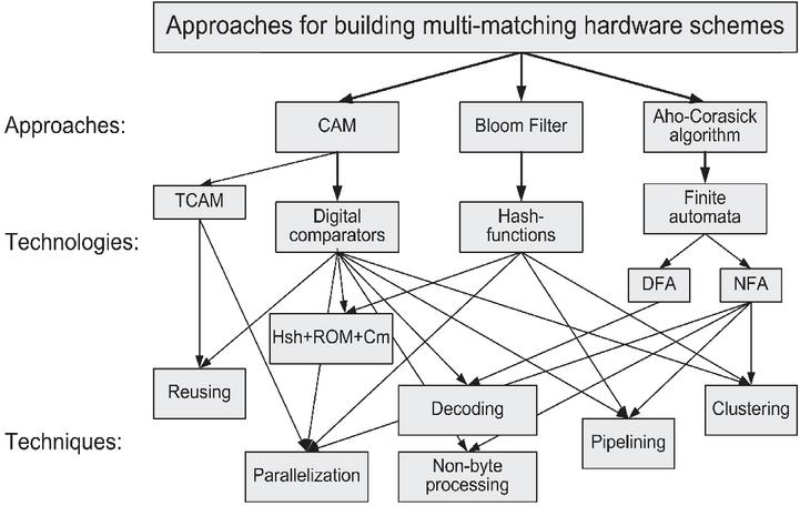
Figure 1 The main approaches, technologies and techniques for building matching circuits for cybersecurity systems [11].
A study of the world experience in designing reconfigurable cybersecurity systems shows that developers, in an effort to achieve greater efficiency, use circuitry solutions of a very different nature [4, 10]. After trying one or another approach and encountering certain difficulties, researchers propose numerous modifications, techniques and tricks to improve the basic scheme (Figure 1).
The analysis of known developments and examples of reconfigurable security systems reveals the following three most promising approaches:
• Content-addressable memory (CAM) based on digital comparators (DC) [12–14];
• Bloom filter (BF) based on hash functions [15–17];
• Aho–Corasick algorithm on finite automata (AC-FA) [18–20].
A comprehensive analysis of world studies in this area conducted in [10] consider technologies, approaches and its modifications for every of these three directions, analyzing the advantages and drawbacks of each approach, the possibilities for improving the technical characteristics, the complexities of implementation on FPGAs and the ways to overcome them.
In order for developers to be able to systematically, at a high scientific level, operate with numerous options for circuit solutions, they must skillfully possess their qualitative as well as quantitative characteristics. Therefore, developers critically need some tools for qualitative and quantitative analysis of both reconfigurable cybersecurity systems in general and their components as well.
For the qualitative analysis a hierarchy of efficiency criteria and corresponding indicators is considered on the example of such signature cybersecurity systems as NIDS. Intrusion detection systems have historically been the first and, accordingly, the most studied FPGA-based information security systems, and we can use them without losing the generality of reasoning. To determine the performance indicators that are important for qualitative analysis and organize them into a hierarchical structure, we studied a lot of practical results published by many developers of information security systems based on FPGA, primarily NIDS.
The quantitative values of the technical characteristics of reconfigurable cybersecurity systems can be found by performing a digital circuit synthesis procedure using an appropriate CAD tool, for example from the manufacturer of the FPGA being used (for example, the WebPack ISE for FPGAs from AMD/Xilinx [21]). But this process contains several complex steps and consumes too much time [22]. The method of accelerated quantitative assessment of the technical characteristics to be discussed is based on the use of the so-called estimation functions (EF) and doesn’t require the use of costly procedures of full synthesis.
The rest of this paper is organized as follows: Sections 2 and 3 consider the qualitative and quantitative assessment tools respectively. Experiments to test the tools proposed are performed in Section 4. Discussions are given in Section 5. Finally, conclusions are drawn and the future research is discussed in Section 6.
2 Qualitative Assessment
To evaluate the properties of reconfigurable cybersecurity systems and their components and to compare different approaches and individual technical solutions, it is necessary to define efficiency criteria and correspondent indicators.
The efficiency criteria of any digital device include the amount of hardware costs, speed of action and set of functions to be performed. The analysis of available knowledge allows revealing the hierarchy of efficiency indicators (EI) as follows.
All indicators can be divided into main and intermediate ones (Figure 2). The main EIs are cost indicators, performance indicators and functional indicators. Intermediate EIs bind some of the main ones.
2.1 Cost Efficiency Indicators
Cost EIs are: the amount of programmable logic resources, which are needed to create a digital circuit; memory costs – both internal (logic cell flip-flops) and BRAM memory blocks, also external to the FPGA chip on-board memory of the reconfigurable accelerator, as well as other costs that can be estimated in numerical units.
It is worth noting here that although cost indicators (as well as performance indicators) are inherently quantitative parameters, in this context they can also be used for qualitative evaluating and comparing approaches and technical solutions. Using them in this sense involves operating with the concepts of “relatively high cost” or “relatively low costs”, etc.
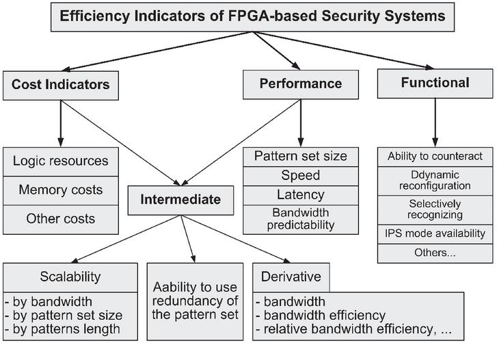
Figure 2 Hierarchy of efficiency indicators.
2.2 Performance Efficiency Indicators
Performance indicators include, on the one hand, the size of the pattern set (the number of different patterns to be recognized), and on the other hand, the speed of the tool, which is characterized by the processing time, by bandwidth, or by latency.
An important qualitative EI of this category is also the predictability of bandwidth, that is, the ability of the device to provide a predetermined operating rate (Deterministic performance) [19]. Some algorithms for single or multiple pattern recognition, for example, Boyer–Moore or Wu–Munber, which use certain heuristics to increase their throughput on average, depending on the input data, change the processing speed in a wide range [23]. At the same time, other algorithms, for example, Aho–Corasick [18], have deterministic performance.
The bandwidth predictability feature makes it easier to deal with other speed characteristics of the system and facilitates the integration of the recognition module with the rest of the technical system components and improves the usability of cybersecurity systems.
2.3 Functional Efficiency Indicators
Let’s consider some of the EIs of NIDS that are functional. The most common among them are mainly qualitative indicators:
• The ability to counteract attacks aimed at cybersecurity systems or other information defense tools;
• The ability to update the pattern set without stopping the recognition process (property of dynamic reconfiguration);
• The ability to chose a subset of recognized patterns by external command (property of selective recognition);
• Ability of NIDS to operate in the intrusion prevention mode.
Note that the last of the mentioned indicators is inherent only to intrusion detection systems.
When creating some security systems, special requirements occur, as a result additional functional indicators can appear.
2.4 Intermediate Efficiency Indicators
Intermediate EIs, as mention above, displays the relationship between main EIs.
Scalability indicators, which relate speed characteristics to cost characteristics, are important for evaluating the effectiveness of reconfigurable computing tools. Scalability is the ability of a technical solution to increase performance characteristics without excessive additional costs [19].
There are three types of scalability:
• By bandwidth (Speed scalability) [24];
• By the volume of the pattern set (Rule-set scalability) [25];
• By the length of the patterns (Pattern length scalability) [24].
An important intermediate indicator is the ability to use redundancy of the pattern set in order to improve speed and resource characteristics. Due to the self-similarity effect, the information contained in the signature database is redundant. A cybersecurity systems’ ability to use this redundancy to improve its effectiveness is its useful property.
The rich experience of creating and using reconfigurable cybersecurity systems by the world community highlighted the need for universal and generalizing indicators that would combine the properties of both cost and speed indicators. Accordingly, a number of indicators were proposed, which in quantitative terms have the form of a certain functional dependence (mathematical expression of arbitrary complexity) on the main quantitative EIs. Such indicators are best suited for quantitative evaluation of the effectiveness of technical solutions and their components. Let’s call such EIs derivative indicators.
2.5 Comparison of the Most Promising Approaches to Building Matching Schemes
Having the developed system of qualitative efficiency indicators allows comparing different technical solutions, in particular, approaches to building matching schemes for signature-based cybersecurity systems.
Table 1 presents the results of a quantitative analysis of the most promising approaches mentioned in the Introduction section. It shows whether the determined EI is a medium/significant advantage or a medium/significant drawback of each approach.
Table 1 Comparison of main matching schemes for reconfigurable NIDS [10]
| Approach | ||||
| Parameter | CAM | Bloom Filter | Aho–Corasick | |
| Logic costs | ||||
| Memory costs | distributed | |||
| BRAM | ||||
| onboard | ||||
| Speed | ||||
| Speed predictability | ||||
| Functional parameters | the ability to counter attacks targeted at the security system | |||
| dynamic update | ||||
| selective recognition | ||||
| ability to work in NIPS mode | ||||
| Scalability | by bandwidth | |||
| by pattern set size | ||||
| by pattern length | ||||
| Ability to use redundancy of pattern set | ||||
| A significant drawback that negates the main advantages of the approach | Excessive resource costs | Fixed pattern length | “Explosive” memory growth | |
| Notation: “”– medium advantage; “” – significant advantage; “” – medium drawback; “ ” – significant drawback. | ||||
The analysis leads to the conclusion that each of approaches has its own positive features and disadvantages [10]. But none of the approaches demonstrates total superiority over others. Any advantage in one of the indicators turns into a disadvantage in other ones. As a result, none of them can be called the leading approach acceptable for the vast majority of cybersecurity applications. Moreover, each approach has at least one significant drawback, which, in fact, negates its main advantages (see the last row in the table).
For example, DC-based CAMs and their modifications provide maximum performance, but are more expensive than other approaches in terms of hardware costs and power consumption. They also do not have excellent scalability. The Bloom filter is more scalable and resource efficient, but imposes a limit on the patterns length distribution property. It also requires additional cost to verify the results obtained due to its inherent probability of false positive errors during matching. Finite automata are modest in terms of logic resources consumption, provide stable but relatively low throughput, are difficult to build, and lead to an “explosive” increase in memory costs for large pattern sets.
The efficiency parameters discussed in detail above make it possible to qualitatively evaluate various technical solutions for signature-based cybersecurity systems. However, for productive work, developers of hardware matching devices need also a rapid tool for their quantitative assessment. The specifics of programmable logic, which is used as the basis for reconfigurable systems, is such that the full cycle of synthesis of a complex digital circuit on an FPGA requires an unacceptably time costs. The problem is exacerbated when it is required to calculate quantitative technical characteristics to find the objective function inside the optimization procedure cycle, for example, when combining different approaches in one device to maximize the total effectiveness of the resulting scheme [26].
3 Quantitative Assessment
3.1 Method for Quick Quantitative Evaluation
As evidenced by the qualitative analysis of reconfigurable signature cybersecurity systems, the main quantitative technical characteristics of matching schemes are resource and speed parameters. Other indicators can either be presented through these two, or are fundamentally impossible to evaluate with numerical values.
The essence of the accelerated method for quantitative evaluation of the technical characteristics of the components of signature cybersecurity systems based on FPGA is that for each i-th component of which the means of protection consists (its most critical component is the recognition module), an EF is created. Such a function for a given matching scheme, which must be synthesized inside a RA with known parameters, and a given set of patterns , which this circuit must recognize, outputs two numerical estimates: the resources (hardware costs) required to create this circuit, and the time delay that it will have after synthesis: . In fact, the EF consists of two parts – the resource component (RC) and the time component (TC).
If the construction of the TC usually does not cause difficulties (the signal propagation delay inside the circuit consists of individual delays of the subcircuits connected in series, and is equal to the maximum delay of subcircuits connected in parallel), then the calculation of the RC is not a trivial task. Various resources are spent when synthesizing circuits in reconfigurable accelerators: look up tables (LUT), flip-flops, memory devices of various types – such as, for instance, the internal block memory of the FPGA and the on-board memory of the RA, which is external to the FPGA.
In order to ensure the methodical rigor of comparing technical solutions, it is necessary to reduce the calculation of resources of different types to some single conventional unit. Such a unit can be some minimal structural element of the FPGA, for example, a LUT. Then it can be assumed that all calculations are performed in conventional look up tables (CLT). Using this approach, we can write the value of the resources required for the synthesis of the i-th component of the computing scheme in such form:
| (1) |
where is the volume of FPGA logic resources (number of LUTs); is the amount of resources of the FPGA distributed memory (the number of flip-flops); – FPGA block memory volume (Mbit); – on-board memory of the reconfigurable accelerator (Mb); – coefficients of bringing resources of various types to the CLT.
Of course, the list of resources used in the creation of reconfigurable devices can be wider in general (for example, it can include memory components such as High Bandwidth Memory (HBM) from newest AMD/Xilinx FPGA devices [27]). The advantage of the somewhat simplified expression (1) is that the list of resources involved in it will be acceptable for most FPGAs that are currently available for use, including the most simple and inexpensive devices. On the other hand, if necessary, it is not difficult to add new terms to (1) and adjust the calculations. That is, the abbreviated expression (1) does not limit the scope of use of the proposed method.
Since the properties of a pattern set are of essential importance in the construction of EFs, let us consider auxiliary statements that will simplify the process of formalization and operation with them.
3.2 Handling Patterns
We present a set of patterns to be recognized in the following form:
| (2) |
where is a set of patterns, that is, fixed sequences of symbols, while the code of each symbol belongs to a certain alphabet (in the case of byte encoding ); – the number of patterns in the set, – the total number of symbols in the set of patterns; and – the length of the shortest and longest pattern in the set; – length distribution function; and – the first and second self-similarity functions; is the first partial self-similarity function.
Formula (2) assumes that the patterns in the set are ordered as follows. Let’s sort all the patterns in the set in ascending order of their length. The patterns of the same length form the so-called batches, and it does not matter how they are ordered inside the batches. Let’s enter the index as follows. First, its value corresponds to the length of the patterns in the pack, starting with the shortest patterns:
Secondly, each subsequent value of the index is necessarily one more than the previous one, that is, there are no gaps in the numbering. Then the length of each pattern in the set will match the index of its package: . But the reverse statement is false, because for some indices there may be no patterns of the corresponding length. Therefore, the number of batches in the pattern set is generally smaller than the difference between the lengths of the extreme dimensions ().
The length distribution function as a function of the index is equal to the number of patterns in the corresponding package: . With the help of the function, it is not difficult to calculate the number of symbols in the set of patterns and the number of non-zero packets.
The self-similarity functions , , – are quantitative parameters of a certain pattern set that characterize the degree of similarity of patterns among themselves. In fact, these functions determine the redundancy present in the set of patterns. This can be used to reduce the number of comparison operations when solving the problem of multiple pattern recognition, that is, to reduce resource costs when creating a cybersecurity system matching module. In a practical sense, the function simplifies calculations for circuit modification DCAM of the base scheme BsCAM on content-addressable memory approach; the function simplifies calculations for other circuit modification – DpCAM; function is found algorithmically when calculating the quantitative characteristics of circuits based on the Aho–Corasick approach [18].
If new efficient pattern matching schemes, significantly different from the known ones, are invented, it is possible to define new self-similarity functions to describe pattern sets.
3.3 Creating Estimation Functions
Below are some examples of estimation functions for the most promising matching schemes and their modifications.
The principle of construction of RC of EF of a digital scheme consists in calculating hardware costs of all kinds, namely LUTs, flip-flops, memory blocks, etc., and reducing them to a single unit of measurement according to formula (1). The TC of EF is calculated according to theoretical information on the delay of signal propagation in the component parts of the circuits, taking into account their interconnections.
For different matching schemes, the sequence of actions in determining the EF and its final form will differ. For some technical solutions, it is possible to create separate techniques for compiling the RC or TC of the estimation function. But the general principle of formation of EFs remains unchanged.
For example, if we have to find the resource component of the estimation function for the base scheme BsCAM (built on content-addressable memory using digital comparators), we consider its circuit and simply calculate all LUTs and flip-flops it contains taking into account the pattern set this scheme has to recognize [26]. Having performed all the necessary calculations, we get the expression for the RC of EF:
where is a qualifier function that determines the number of LUTs needed for recognizing one byte of information depending of the number x of LUT inputs: ; y is the load capacity (maximum fan-out value) of the outputs of FPGA internal components for the given RA.
As we can see the expression (3.3) contains variables , which are parameters of a set of patterns, and constants . The absence of coefficients and in (3.3) indicates that BsCAM scheme doesn’t use memory resources. The absence of self-similarity functions indicates that this scheme doesn’t use the redundancy that is inherent in the dictionary of signatures, which is its disadvantage.
The time component of the EF for BsCAM can be taken as equal to the period of the clock frequency of the digital circuit, obtained during several completed full synthesis procedures. Taking into account the non-linear dependence of the clock frequency on the resources amount, the EF TC of this scheme can be presented as follows:
| (4) |
where , and are empirically found coefficients of the quadratic approximation of the functional dependence of the maximum clock frequency of the digital circuit synthesized in the FPGA on resource costs; is the amount of hardware costs (in CLT), obtained by formula (3.3); is the frequency division coefficient, which indicates how many times the clock frequency differs within the “fast” and “slow” zones according to the technique of dividing the digital circuit into time zones [14].
Therefore, obtaining a TC (as opposed to a RC) may require synthesizing the device one or more times. But when further multiple using, the need for synthesizing procedure disappears.
Let’s look at a few more EF RC examples for other solutions to better understand their features.
A similar direct calculation of the hardware resources of the decoded CAM (DCAM) modification leads to the following form of EF RC:
where is the maximum possible delay value of the digital delay circuit built on the LUT of the given FPGA; NotZ() is a zero inequality function.
As we can see the DCAM scheme also uses only two types of FPGA resources (the expression (3.3) doesn’t includes and coefficients), however, it uses the redundancy of pattern set (the first self-similarity function is present), i.e. the DCAM modification is more effective in comparison to the base BsCAM solution.
The EF RC expression for modification DpCAM turns out to be even more complicated:
| (6) |
Nevertheless, it contains almost only addition and rounding operations, which is not computationally difficult when calculating by computer.
The presence of the first partial self-similarity function in (6) indicates the use of signature redundancy by the DpCAM recognition scheme.
The time component of the EF for the DCAM and DpCAM schemes are the same as for the basic scheme (4).
The EF RC for the simplified Bloom filter (SBF) pattern matching scheme [15] is as follows:
| (7) |
where is recognition error factor, which is numerically equal to the number of hash functions in the BF (is inversely proportional to the logarithm of the probability of false positive, which is acceptable for a particular application of the Bloom filter); is number of ports of block memory BRAM; is length of the patterns that are recognized by this BF; is the bit width of the hash-function generators (where is the value of the pattern length distribution function at ). Note that the Bloom filter-based circuit can only recognize patterns of the same length. To use it in NIDS systems, it is necessary to organize the parallel operation of several SBF.
As we can see the expression (7) contains coefficients and , that is SBF scheme uses three types of FPGA resources: LUTs, flip-flops and block RAM. On the other hand it doesn’t include any self-similarity functions, i.e. the BF scheme doesn’t use the inherent redundancy of pattern set.
Expression (4) can also be used when creating a TC for BF-based circuits, since due to pipelining the block memory access delay can be reduced to one cycle. But the need for an additional stage of correcting the output of the BF (because of the inherited false positive recognition error) under certain circumstances can reduce the performance of the device several times.
The resource component of estimation function for the Aho-Corasick finite automaton using block memory scheme ACBRAM has such appearance as:
where and are numbers of LUTs and flip-flops required to create a control device for AC-FA respectively, which can be found by a certain approximating technique; is amount of memory (in Kbits) in one BRAM block of the given FPGA (excluding parity bits, if any); is the number of BRAM blocks required, where is amount of block memory required for the ACBRAM scheme (in Mbits), which is the sum of the amounts of memory for direct, cross, failure and post-start transitions of the AC FA: ; is the width (in bits) of data stored in BRAM (depending on the technique used to build the finite automaton).
The EF TC value for the ACBRAM is the product of the delay of the access to the block memory and the average number of accesses to the BRAM per cycle of the finite state machine:
| (9) |
where , , , and are the number of accesses to the RAM per cycle of the finite automaton in the case of making a direct, cross, false, post-start transition and receiving an acceptable state code, respectively; , , , and are sizes of memory (in bytes) needed to store direct, cross, false and post-start transitions and match vectors, respectively.
4 Experiments
4.1 Combining Approaches to Building Matching Schemes
The lack of the best approach to the construction of the recognition schemes, which would surpass competitive solutions in all parameters, leads to the idea of combining different schemes in one device to maximize the overall efficiency of the obtained scheme [26]. (Such a task even more requires a quick quantification that can be performed inside the optimization procedure).
The basis of this idea of structural combining is that the patterns included in the signature database differ among themselves in terms of length, self-similarity properties, etc. Therefore, the efficiency of processing certain patterns by different schemes also differs depending on the scheme involved. So, theoretically, it is possible to choose the most suitable recognition scheme for each category of patterns. The implementation of this idea is the structural joining of several matching blocks (MB), built using different approaches, into a single pattern recognition module (PRM) [14]. The set of patterns to be recognized is distributed among the MB in such a way that the advantages of each approach are maximized and the disadvantages are minimized.
The greatest efficiency is achieved by applying the mathematical optimization apparatus both to the processes of pattern distribution and selection of technical solution for each MB. But the optimization procedure requires repeated calculation of the target function, which includes the quantitative characteristics of the hardware components of signature cybersecurity system. On the other hand, the method for quantitative evaluation considered in this study is able to provide a quick calculation of such characteristics at each step of the iterative procedure of finding the extremum of the target function. Therefore, it is advisable to test its capabilities on the example of the implementation of the principle of constructive combination.
4.2 Experiments
You can combine MB in different ways. They can be connected in parallel, in series or, in general, form a complex hierarchical structure. Let’s consider a simple example – a parallel structural joining – to test the method of accelerated calculation of the quantitative characteristics of reconfigurable components.
Assume that the PRM of a cybersecurity signature system consists of two matching blocks, MB and MB, connected in parallel [26]. A data stream to be checked for malicious content is simultaneously fed to the inputs of both matching blocks. It is necessary to distribute a set of patterns among them so that the total amount of hardware resources required to create the entire PRM is minimal.
A pattern set can be sorted by some feature, for example, by length, by the number of patterns in the batch, or by the product of the number of the patterns in the batch by their length. All patterns starting from the minimal value according to the selected sort order till the one having number j will be given data for the MB synthesis. The rest – for synthesis of MB.
In Figure 3, the results of resource cost minimization are depicted under the following conditions:
• Implementation of MB – BsCAM scheme, MB – full-size (large) Bloom filter (LBF) scheme;
• Sorting order – length multiplied by the number of patterns in the batch (descending);
• A set of patterns is used from the freely distributed signature database Community Ruleset from the open NIDS Snort version 3.0, which contains templates with a length from to , total characters ;
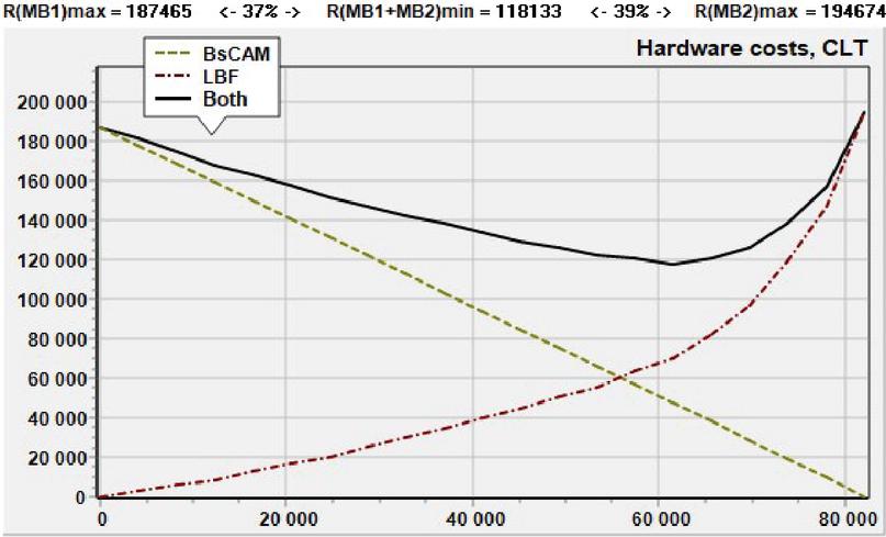
Figure 3 Resource cost minimization for the BsCAM and LBF matching schemes combined in parallel.
• The type of RA is the VC709 Evaluation Kit from Xilinx based on the Virtex-7 VX690T FPGA device from Xilinx.
Along the abscissa axis in Figure 3, the number of characters in the patterns submitted for recognition to MB is plotted, the rest of the patterns are submitted to MB. The far left point means that all patterns are recognized by MB and none by MB; the far right point corresponds to the case when, on the contrary, all patterns are recognized by the MB block. Along the ordinate axis are the hardware costs (in CLT) for the synthesis of each MB and together for the PRM that contains them both.
Figure 4 An example of unsuccessful parallel combining.
As we can see, in Figure 3, the cost curve for PRM has a pronounced minimum at which the entire PRM consumes 37% less resources than MB (if it recognizes all patterns by itself) and 39% less than MB (if it recognizes all patterns). That is, the combined scheme demonstrates 37% better efficiency (in terms of hardware costs) than the better of the two MBs alone.
In practice, a successful result of a parallel combining, similar to the one shown in Figure 3, is not always obtained. More often, one of the matching blocks shows better results than in combination with any other. Such an example is shown in Figure 4, where the same recognition schemes are used, but to recognize patterns from the set of Web_server.rules (attacks on web servers), taken from the signature database of free NIDS Suricata version 5.0. The set contains 999 patterns from one to 233 characters long, with a total of 19752 characters. Under these conditions, the cost of creating MB in the case that it recognizes the entire pattern set is several times less than the cost of creating MB in the case that it recognizes the same pattern set. As we can see, the PRM created by paralleling MB and MB is more expensive with any distribution of patterns among them.
A significant difference in the absolute values of resource costs is not the only limitation.
The discrepancy between the speed characteristics of MB also imposes restrictions on the successful use of parallel connection of recognition units.
But the results of the experiments show that close resource costs and operation speed conformity don’t guarantee a positive effect from the parallel combination of MBs, if their EFs have a similar form. This fact becomes clearer when realizing that a distinct minimum, as shown in Figure 3, can’t occur if the curves MB and MB are similar (mirror-reflected).
Analyzing and summarizing the results of experiments with EFs for different situations, we can formulate the following two conditions for successful parallel combining.
underlineCondition 1. Technical characteristics of MB should be close enough in terms of absolute values of both resource costs and time characteristics.
Figure 5 Examples of curves for different matching schemes (sorting order – descending pattern length).
underlineCondition 2. Functional dependences of the technical characteristics of MB on the distribution of patterns, on the contrary, should differ significantly in the shape of their curves.
To provide the both Conditions when parallel combining reconfigurable matching blocks, for a given pattern set it is necessary to choose MB with maximally different dependencies of their hardware costs on the pattern distribution and similar values at the end point of curve, taking into account the speed consistency.
Figure 5 depicts several hardware costs dependency curves for certain matching schemes, which have significantly different shapes.
It is possible to adjust properties of matching schemes in some limits due to applying certain techniques and tricks. For instance, parallelization, pipelining, using non-byte principles of information processing and other methods allow realizing some trade-offs.
It is important to note, that Conditions 1 and 2 would be practically impossible to unveil without the use of the accelerated quantification method, because for each point of each experimental curve it would be necessary to perform a full cycle of the time-consuming process of synthesizing a digital circuit using a CAD tool.
5 Discussion
As mentioned above, potential consumers of the proposed tools are developers of FPGA-based cybersecurity systems. Previously, faced with an abundance of possible technical solutions, they had to use predominantly heuristic approaches and act intuitively. The proposed tools allow them to act more meaningfully and theoretically justified.
Now developers can analyze a large number of known solutions, and choose the most suitable for a particular task. Moreover, the rapid quantification method allows them to automate the process of choosing the optimal solution for a specific pattern set and even create adaptive cybersecurity systems that maintain optimal hardware realization under changing external conditions.
The disadvantages of the proposed tools include the following.
The hierarchy of performance indicators is based on a rich empirical experience of developers and therefore does not guarantee functional completeness.
The rapid quantification method, when evaluating performance and hardware costs, does not take into account the auxiliary components of FPGA-based cybersecurity systems (for example, packet receiving module, classifier of headers, packet filter, packet sending module, etc. [22]), which may affect the accuracy of estimates. On the other hand, since the purpose of the method is to compare the characteristics of the matching circuits, the remaining unchanged components of the system will introduce the same distortions, which therefore will not significantly worsen the result of the comparison.
6 Conclusion and Future Work
There are many different approaches to building reconfigurable hardware circuits to perform the computationally intensive multi-pattern matching task in signature-based cybersecurity systems such as NIDS, antivirus, worm protection systems, and spam filters. Qualitative and quantitative analysis is necessary for developers of such systems to more effective work with a large number of technical solutions in this area.
The contribution of authors is as follows.
We consider the classification of efficiency criteria and related indicators as a tool for qualitative analysis of recognition schemes for such systems.
As a quantitative assessment tool, a method for rapid evaluation of the quantitative characteristics of reconfigurable signature-based cybersecurity systems and their components is proposed. The method is based on the use of so-called estimation functions and allows avoiding the time-consuming procedure of synthesizing a digital circuit using proprietary CAD. Therefore the developers of hardware-accelerated cybersecurity systems can now use optimization apparatus by applying rapid quantification method at each iteration within the optimization procedure cycle.
A technique for handling patterns of signature database as well examples of estimation functions for the most promising matching schemes and their modifications were provided. The expressions for the estimation functions given in the paper are suitable for direct use by developers of FPGA-based cybersecurity systems.
A number of experiments were performed to test the provided tools on the example of the problem of parallel structural combining various technical solutions for constructing optimal pattern recognition modules.
It is also worth mentioning that the rapid quantification method can also be applied to building complex reconfigurable digital systems in other areas.
Further work in this direction, obviously, should be aimed primarily at eliminating the shortcomings mentioned in the previous section.
First, it may be possible to logically generalize the hierarchy of performance indicators to compensate for the lack of functional completeness.
Secondly, it seems useful to conduct experiments to assess the accuracy of estimation functions by comparing their output data with the quantitative characteristics of real digital projects synthesized in FPGAs for different matching schemes.
The availability of an accelerated quantification method now allows more experiments to study signature databases of existing cybersecurity systems, which can reveal deep properties and regularities in these databases. The result may be a closer integration of signature method with the latest non-signature approaches, many of which successfully use artificial intelligence technologies [28–30].
Acknowledgments
This paper was supported in part by the Informatization Program of the National Academy of Sciences of Ukraine for 2020–2024.
References
[1] Stetsenko, I. V., and M. Demydenko. 2020. Signature-based Intrusion Detection Hardware-Software Complex. Information & Security, vol. 47, no. 2, pp. 221–231. doi: 10.11610/isij.4715.
[2] Díaz-Verdejo, J., J. Muñoz-Calle, A. E. Alonso, R. E. Alonso, and G. Madinabeitia. 2022. On the Detection Capabilities of Signature-Based Intrusion Detection Systems in the Context of Web Attacks. Applied Sciences (Switzerland), vol. 12, no. 2:852. doi: 10.3390/app12020852.
[3] B. Smyth. 2003 Computing Patterns in Strings. Essex: Pearson Addison Wesley, 423 p.
[4] Chen, H., Y. Chen, and D. H. Summerville. 2011. A Survey on the Application of FPGAs for Network Infrastructure Security. IEEE Communications Surveys and Tutorials, Article vol. 13, no. 4, pp. 541–561. doi: 10.1109/surv.2011.072210.00075.
[5] Jyothi, V., S. K. Addepalli, and R. Karri. 2018. DPFEE: A High Performance Scalable Pre-Processor for Network Security Systems. IEEE Transactions on Multi-Scale Computing Systems, Article vol. 4, no. 1, pp. 55–68. doi: 10.1109/tmscs.2017.2765324.
[6] Park, T., J. Nam, S. H. Na, J. Chung, and S. Shin. 2021. Reinhardt: Real-time Reconfigurable Hardware Architecture for Regular Expression Matching in DPI. ACM International Conference Proceeding Series, pp. 620–633. doi: 10.1145/3485832.3485878.
[7] Nam, J., S. H. Na, S. Shin, and T. Park. 2022. Reconfigurable regular expression matching architecture for real-time pattern update and payload inspection. Journal of Network and Computer Applications, vol. 208:103507. doi: 10.1016/j.jnca.2022.103507.
[8] Nagaraju, S., B. Shanmugham, and K. Baskaran. 2021. High throughput token driven FSM based regex pattern matching for network intrusion detection system. Materials Today: Proceedings, vol. 47, pp. 139–143. doi: 10.1016/j.matpr.2021.04.028.
[9] Ngo, D.-M., D. Lightbody, A. Temko, C. Pham-Quoc, N.-T. Tran, C. C. Murphy, and E. Popovici. 2023. HH-NIDS: Heterogeneous Hardware-Based Network Intrusion Detection Framework for IoT Security. Future Internet, vol. 15, no. 1, pp. 9. doi: 10.3390/fi15010009.
[10] Hilgurt, S. Ya. 2021. A Survey on Hardware Solutions for Signature-Based Security Systems. 1st International Workshop on Information Technologies: Theoretical and Applied Problems 2021 (ITTAP 2021), Ternopil, Ukraine, 16–18 Nov. 2021. – CEUR Workshop Proceedings, vol. 3039, pp. 6–23. Available at: http://ceur-ws.org/Vol-3039/
[11] Hilgurt, S. 2021. A Concise Review of FPGA-based Hardware Solutions for Network Intrusion Detection. IEEE 8th International Conference on Problems of Infocommunications, Science and Technology (PIC S&T), pp. 164–168. doi: 10.1109/PICST54195.2021.9772171.
[12] Guccione, S. A., D. Levi, and D. Downs. 2000. A reconfigurable content addressable memory. Parallel and Distributed Processing, Proceedings, Article; Proceedings Paper, vol. 1800, pp. 882–889.
[13] Sourdis, I., and D. Pnevmatikatos. 2004. Pre-decoded CAMs for efficient and high-speed NIDS pattern matching. 12th Annual IEEE Symposium on Field-Programmable Custom Computing Machines, Proceedings, Proceedings Paper, pp. 258–267. doi: 10.1109/fccm. 2004.46.
[14] Sourdis, I., D. N. Pnevmatikatos, and S. Vassiliadis. 2008. Scalable multigigabit pattern matching for packet inspection. IEEE Transactions on Very Large Scale Integration (VLSI) Systems, Article vol. 16, no. 2, pp. 156–166. doi: 10.1109/tvls1.2007.912036.
[15] Bloom, B. H. 1970. Space/Time Trade-offs in Hash Coding with Allowable Errors. Communications of the ACM, Article vol. 13, no. 7, pp. 422–426. doi: 10.1145/362686.362692.
[16] Dharmapurikar, S., M. Attig, and J. Lockwood. 2004. Design and Implementation of a String Matching System for Network Intrusion Detection using FPGA-based Bloom Filters. All Computer Science and Engineering Research, Washington University in St. Louis, Report Number: WUCSE-2004-12, 2004-03-25.
[17] Geravand, S., and M. Ahmadi. 2013. Bloom filter applications in network security: A state-of-the-art survey. Computer Networks, Article vol. 57, no. 18, pp. 4047–4064. doi: 10.1016/j.comnet.2013.09.003.
[18] Aho, A. V., and M. J. Corasick. 1975. Efficient String Matching: An Aid to Bibliographic Search. Communications of the ACM, vol. 18, no. 6, pp. 333–340. doi: 10.1145/360825.360855.
[19] Lunteren, J. 2006. High-performance pattern-matching for intrusion detection. 25th IEEE International Conference on Computer Communications, Vols 1–7, Proceedings IEEE Infocom 2006, Proceedings Paper, pp. 1409–1421.
[20] Jiang, W., Y. H. E. Yang, and V. K. Prasanna. 2010. Scalable multi-pipeline architecture for high performance multi-pattern string matching. 24th IEEE International Parallel and Distributed Processing Symposium, IPDPS 2010, Atlanta, GA, pp. 1–12. doi: 10.1109/IPDPS.2010.5470374.
[21] AMD/Xilinx. [Online]. Available at: www.xilinx.com.
[22] Evdokimov, V., A. Davydenko, and S. Hilgurt. 2021. Using GRID for Centralized Synthesis of FPGA-based Information Security Systems. Pattern Recognition and Information Processing (PRIP’2021): Proceedings of the 15th International Conference, Minsk, Belarus, 21–24 Sept. 2021. – Minsk: UIIP NASB, pp. 115–118.
[23] Antonatos, S., K. G. Anagnostakis, and E. P. Markatos. 2004. Generating realistic workloads for network intrusion detection systems. Proceedings of the Fourth International Workshop on Software and Performance, WOSP’04, pp. 207–215. doi: 10.1145/974043.974078.
[24] Dharmapurikar, S., and J. Lockwood. 2005. Fast and scalable pattern matching for content filtering. 2005 Symposium on Architectures for Networking and Communications Systems (ANCS), Princeton, StateNJ, USA, pp. 183–192. doi: 10.1145/1095890.1095916.
[25] Lunteren, J., and T. Engbersen. 2003. Fast and scalable packet classification. IEEE Journal on Selected Areas in Communications, Article; Proceedings Paper vol. 21, no. 4, pp. 560–571. doi: 10.1109/jsac.2003.810527.
[26] Hilgurt, S. 2020. Parallel combining different approaches to multi-pattern matching for FPGA-based security systems. Advances in cyber-physical systems, vol. 5, no. 1, pp. 8–15. doi: 10.23939/acps2020.01.008.
[27] AMD/Xilinx “Virtex UltraScale+ HBM FPGAs provide the highest on-chip memory density with up to 500Mb of total on-chip integrated memory, plus up to 16GB of high-bandwidth memory (HBM) Gen2 integrated in-package for 460GB/s of memory bandwidth”. [Online]. Available at: www.xilinx.com/products/silicon-devices/fpga/virtex-ultrascale-plus-hbm.html.
[28] Zhang, J., L. Pan, Q. L. Han, C. Chen, S. Wen, and Y. Jiang. 2022. Deep Learning Based Attack Detection for Cyber-Physical System Cybersecurity: A Survey. IEEE/CAA Journal of Automatica Sinica, vol. 9, no. 3, pp. 377–391. doi: 10.1109/JAS.2021.1004261.
[29] Rizvi, S., M. Scanlon, J. McGibney, and J. Sheppard. 2022. Deep Learning Based Network Intrusion Detection System for Resource-Constrained Environments. The 13th EAI International Conference on Digital Forensics and Cyber Crime.
[30] Sha’ari, A. S., and Z. Abdullah. 2022. A Comparative Study between Machine Learning and Deep Learning Algorithm for Network Intrusion Detection. Journal of Soft Computing and Data Mining, vol. 3, no. 2, pp. 43–51.
Biographies

Sergii Ya. Hilgurt, a Senior Researcher of Pukhov Institute for Modelling in Energy Engineering (PIMEE) of NAS of Ukraine since 1992, he received the scientific degree PhD in “Computing machines, complexes, systems and networks” from the graduate school of the Institute for Modelling in Energy Engineering, Kyiv, Ukraine, in 1990. From 1994 to 2008 he worked part-time at oil-pipelines automation company GERAX. From 2000 to 2004 he studied at the Doctorate of PIMEE. In 2015 he was awarded the scientific title of Senior Researcher in “Computer systems and parts”. He received the scientific degree Doctor of Technical Sciences in “information protection systems” from the specialized scientific council of PIMEE in 2021. He is the author of three books, two preprints, five inventions, and 85 articles. His research interests include: factory automation, HPC, FPGA-based network security systems and cybersecurity of critical cyber-physical systems.

Anatolii M. Davydenko, a Leader Researcher of Pukhov Institute for Modelling in Energy Engineering of NAS of Ukraine since 1992, he received the scientific degree PhD in “Elements and devices of computer technology” from the graduate school of the Institute for Modelling in Energy Engineering, Kyiv, Ukraine, in 1990. In 1995–1996 he worked in the Main Department of Civil Service under the Cabinet of Ministers of Ukraine. From 1996 to 2000 he studied at the Doctorate of PIMEE. In 2001 he was awarded the scientific title of Senior Researcher in “Progressive Information Technologies”. He received the scientific degree Doctor of Technical Sciences in “Information Security Systems” from the specialized scientific council of PIMEE in 2021. He is the author of 5 books and tutorials, 7 inventions, and more than 100 articles. His research interests include: mathematical modelling and analysis of information threats in automated systems, examination of software and hardware subsystems of information protection systems, artificial intelligence methods of information security.
Tetyana V. Matovka received a master’s degree in banking at the Uzhhorod National University in 2008. In 2017, she obtained the degree PhD at Mukachevo State University. She currently works as an associate professor at the Department of finance and banking, Uzhhorod National University, Ukraine. She is the co-author of two collective monographs and more than 15 articles in both domestic and international publications. Her research interests include: development and security of banking technologies.

Mykhailo P. Prygara Graduated from the Kyiv National University of Construction and Architecture with a major in information management systems and technologies in 2010, he obtained the degree PhD at the National Aviation University, Kyiv, Ukraine, in 2018. He is the co-author of a collective monograph and more than 10 articles in domestic and foreign publications. His research interests include: development and security of e-democracy systems.
Journal of Cyber Security and Mobility, Vol. 12_3, 339–366.
doi: 10.13052/jcsm2245-1439.1235
© 2023 River Publishers