Application of Intelligent Cloud Computing Technology in Optical Communication Network Security of Smart Grid
Zhefeng Li1, Botao Hou1,*, Xiaojun Zuo1, Yuling Guo1 and Jianchun Zhou2
1State Grid Hebei Electric Power Research Institute, Shijiazhuang, China
2China Electric Power Research Institute Co., Ltd, Beijing, China
E-mail: lizhefeng@tom.com; houbot@163.com; hbszxj01@163.com; guoyuling18@126.com; xintong-zhoujc@epri.sgcc.com.cn
*Corresponding Author
Received 28 December 2023; Accepted 21 February 2024
Abstract
In order to improve the security of smart grid optical communication network, this paper combines intelligent cloud computing technology to build a security system of optical communication network of power grid. In the aspect of improving communication security performance, multi-user access is realized by non-orthogonal power domain segmentation, and different users use different powers to add and superimpose the same spectrum resources, so as to increase spectrum utilization. At the sending end, this paper improves the safe channel capacity of users by means of pre-coding and artificial noise, and realizes the safe transmission of information. In terms of transmission stability, the cloud computing platform is used as a data processing platform, and multiple nodes are processed synchronously through optical communication state identification, which can more effectively improve the speed of optical communication state identification data. In order to test the performance of the power grid information dispatching model designed in this paper in optimizing power grid configuration and improving power grid load, simulation experiments are carried out. Through the experimental analysis, we can see that the communication method proposed in this paper can accurately identify the intrusion factors, and can effectively improve the security of smart grid optical communication network.
Keywords: Cloud computing, smart grid, optical communication, network security.
1 Introduction
The research on cross domain secure communication in smart grids has always been a hot topic in smart grid research. The main research content involved includes a series of cutting-edge technologies such as smart grid information security technology, distributed security access control technology, multi-agent technology, etc.
Wireless communication network is an essential link for smart grid to achieve high-level management and control. However, due to the strong dependence of smart grid on communication network and the broadcast characteristics of wireless communication, the wireless communication information of power grid is easy to be monitored and stolen by malicious eavesdroppers, which brings new threats to the security system of smart grid. For example, in smart meters in smart grid, eavesdroppers can analyze users’ electricity consumption behavior by eavesdropping on the data transmitted by smart meters, or affect the timely update of real-time electricity prices in the grid, thus threatening the stable operation of smart grid.
Confidentiality of power data. Communication confidentiality protects power data from unauthorized users. A set of authorized restricted information cannot be accessed by unauthorized users to protect personal privacy and proprietary information. Even if unauthorized users steal power data, they cannot decrypt the information. If the electricity consumption data and electricity fees of power users are obtained by unauthorized users, the confidentiality of the data is compromised [1]. Power data authentication and integrity. Integrity means that in a smart grid, authorized user devices can access and save information, while preventing unauthorized users from damaging or even tampering with information. If the data transmitted during the communication process of the smart grid is tampered with by attackers, it may lead to incorrect understanding and decision-making behavior of the power grid control center regarding the operation status of the power grid, affecting the security of the power grid operation [2]. Electricity user certification. Power user authentication can authenticate the legitimate identities of both parties, confirming that they are legitimate users engaged in two-way wireless communication. Privacy protection for power users. Privacy protection is an important security requirement in the practical application and commercialization of smart grid wireless communication. For example, attackers engage in activities that disrupt the stable and safe operation of the smart grid by obtaining information such as device settings and user usage habits [3]. Communication availability. Availability refers to the timely and reliable acquisition of information by authorized personnel within the allowed time. If interference devices are used to interfere with the data upload of smart meters, it will damage the availability of the smart grid system. If the communication availability in the smart grid is compromised, such as hackers attacking the distributed services of the smart grid, interrupting communication between the control center and user equipment, causing power users to be unable to obtain the implementation and operation status of the grid, affecting their electricity consumption decisions [4].
The smart grid closely interacts information, communication, and electricity, improving the efficiency, reliability, and sustainability of electricity, but also leading to the unpredictability and vulnerability of power system failures. Especially the strong coupling between the information layer and the physical layer has introduced security issues to the smart grid [5]. The three core elements of information security in the smart grid security system are availability, integrity, and confidentiality. In the context of the physical layer security of smart grid wireless communication, the meaning of these three elements is: availability. Availability refers to the timely and reliable acquisition of information by authorized personnel within the allowed time [6]. If interference devices are used to interfere with the data upload of smart meters, it will damage the availability of the smart grid system. If the communication availability in the smart grid is compromised, such as hackers attacking the distributed services of the smart grid, interrupting communication between the control center and user equipment, causing power users to be unable to obtain the implementation and operation status of the grid, affecting their electricity consumption decisions [7]. Integrity. Integrity means that in a smart grid, authorized user devices can access and save information, while preventing unauthorized users from damaging or even tampering with information. If the data transmitted during the communication process of the smart grid is tampered with by attackers, it may lead to incorrect understanding and decision-making behavior of the power grid control center regarding the operation status of the power grid, affecting the safety of the power grid operation. Confidentiality. Confidentiality refers to a set of authorized restricted information that cannot be accessed by unauthorized users, protecting personal privacy and proprietary information. If the electricity consumption data and electricity fees of power users are obtained by unauthorized users, the confidentiality of the data is compromised. For example, attackers engage in activities that disrupt the stable and safe operation of the smart grid by obtaining information such as device settings and user usage habits related to the smart grid. The information transmission in smart grids includes two objectives: timeliness and security, which requires system design to have the ability to strike a balance between communication efficiency and information security. Existing research has conducted in-depth research on the communication security issues of smart grids from different perspectives [8]. Reference [9] summarizes the potential security risks faced by smart grids and corresponding security measures from the perspectives of equipment, networking, and anomaly detection. Reference [10] analyzed the data security issues in intelligent networks and will conduct information security research from five stages: data generation, collection, transmission, storage, and processing. Currently, research on the security of wireless communication in smart grids is mainly focused on the design of wired computer networks, that is, the security design of the network layer and above, based on the complete and accurate transmission of information at the physical layer.
Visible Light Communication (VLC) refers to the use of intensity modulation to load information into the radiation of incoherent LEDs (light emitting diodes) used for illumination. The modulated light signal is received by an optical receiver and converted into optoelectronic signals, which are then directly detected and demodulated to provide wireless communication services while meeting the lighting function [11]. Compared to traditional RF (Radio Frequency) communication technology, VLC has unlicensed 400 THz visible light spectrum resources and effective frequency and spatial multiplexing technology, which can provide broadband and high communication rate communication services, effectively alleviating the problem of wireless spectrum resource scarcity and data flow surge. At the same time, VLC systems can efficiently expand high-density VLC access nodes based on existing popular LED lighting equipment systems, effectively reusing the energy required for lighting, and providing dense communication service connections [12]. Moreover, compared to the wavelengths within the traditional RF frequency band, visible light can provide a safer and more reliable communication link for information exchange due to its ultra-short wavelengths of 380 nm–780 nm and weak propagation and diffraction capabilities.
Compared to traditional RF communication systems, VLC systems have their unique characteristics, with the most obvious being the use of intensity modulation and direct modulation for optical signal transmission in VLC systems, which eliminates multipath fading in VLC channels [13]. Specifically, the path attenuation of traditional RF communication is inversely proportional to the second power of distance, while the path loss of optical transmission channels is inversely proportional to the fourth power of distance. Therefore, the attenuation in the visible light band is more severe, making it more suitable for short distance communication scenarios. Therefore, channel modeling and estimation methods applied to traditional RF communication cannot be directly applied to VLC systems. Therefore, it is necessary to design effective channel modeling and estimation schemes based on the propagation characteristics and channel characteristics of VLC, providing accurate channel state information for VLC physical layer design. Due to the similarities between visible and infrared light bands in the transmission channels of wireless optical communication, and the academic community’s research on channel modeling in the infrared light band is relatively mature. Therefore, the channel modeling research of indoor VLC systems heavily relies on various research results of infrared light waves, and on this basis, appropriate adjustments and further improvements are made [14].
The method proposed in reference [15] has become a new development trend in studying multi input and multi output VLC systems composed of VLC channel mode multiple light sources, which can greatly improve spectral efficiency and reliability. Due to the mutual interference between multiple light sources and the complexity of channel models, there has been limited research on channel modeling and estimation for multi light source VLC systems so far. Reference [16] further studied the optimal parameter design by introducing a new universal three-dimensional geometric model and derived analytical expressions for the channel matrix eigenvalues of pure LoS links. In response to the high coherence of the multi input multi output VLC system channels, reference [17] achieved a highly incoherent multi input multi output channel matrix by adjusting the directional angle of the photoelectric receiver. A visible light multi-channel model has been proposed to evaluate the multipath dispersion characteristics of indoor multi input multi output VLC systems.
The key to joint simulation of power information physics systems lies in studying the interaction mechanism and mutual influence between the two, and achieving deep coupling between power physics systems and information communication systems. But the power system is a time continuous system, and its simulation is often driven by discrete time, while the communication system is a discrete system, and its simulation is often driven by discrete events. The essential differences in operating mechanisms lead to very complex data exchange and synchronization between the two [18].
At present, scholars at home and abroad have proposed a large number of joint simulation methods for power information physical systems. According to the platform structure and implementation methods, these schemes can be divided into: simultaneous simulation, non real-time joint simulation, and real-time joint simulation. For the study of VLC channels, predecessors have achieved fruitful research results, which can provide a certain theoretical basis and technical support for this article. However, in the context of balancing the application requirements of lighting and communication integration with complex visible light scenes, how to achieve high simulation accuracy and low computational complexity in VLC channel modeling is an urgent problem to be solved.
The research purpose of this article is as follows: Improve the stability of the power grid: Connect multiple power supply equipment, timely ensure the normal operation of the power grid through the detection and alarm of line faults, and improve the reliability and stability of the power grid. Improving power quality: Real time monitoring of the operation of power grid equipment, controlling the power load of equipment, and improving the quality and efficiency of power transmission Reduce power consumption: Optimized the power grid structure and power configuration, maximizing the reduction of power consumption in the power grid Reduce maintenance costs: By real-time monitoring of power lines and equipment, system faults can be accurately detected and timely located to reduce maintenance costs.
With the introduction of the concept of interoperability, the demand for cross domain interoperability of substations in the power system is becoming increasingly high. In the process of implementing cross domain interoperability, it will inevitably affect the traditional communication model structure between intelligent substations, which also brings new security issues. This also makes it more important to study a new cross domain security communication service model for digital substations.
The innovation of this article lies in proposing new solutions to ensure the security of NOMA VLC systems. In addition, the peak shaving phenomenon in VLC systems can worsen the BER performance of NOMA users. For this issue, this article proposes a signal preprocessing scheme to reduce signal peaks and improve BER performance.
In order to improve the security of smart grid optical communication network, this paper combined with intelligent cloud computing technology to build a network security system of power grid optical communication, so as to eliminate potential safety hazards in power grid communication and improve the scientific development of smart grid.
2 System Model
NOMA achieves multi-user access through non orthogonal power domain segmentation. The basic principle of NOMA is that different users use different powers to add and stack on the same spectrum resources, in order to increase the utilization of the spectrum. Utilize SIC technology at the receiving end to eliminate interference between different users and achieve correct demodulation.
2.1 Security Model of Visible Light Communication System with Non-orthogonal Multiple Access
NOMA (non-orthogonal multiple access) realizes multi-user access through non-orthogonal power domain partition. The basic principle of NOMA is that different users use different power to add and superimpose the same spectrum resources, so as to increase the utilization rate of spectrum. At the receiving end, SIC technology is used to eliminate the interference between different users and realize correct demodulation.
The core idea in NOMA is to use overlay encoding on the sending side, as shown in Figure 1. Superposition Coding (SC) is considered as one of the basic building blocks of the envisaged coding scheme to achieve scalar Gaussian broadcast channel capacity.
At the transmitting end, different transmission powers are allocated to K users according to the channel state information of users. Usually, the sender first sorts the users according to the channel performance difference of each user, that is, according to the size of the channel performance difference. Among them, users with poor channel conditions will be allocated higher transmission power, while users with better channel conditions will be allocated smaller transmission power. If the transmission signals of K users are assumed to be , the signals superimposed through the power domain are:
| (1) |
Among them, represents the transmission power allocated to the -th user, and satisfies , indicating the total transmission power of the system. The superimposed signal is added with a DC component to drive the LED, which is then sent to the free space by the LED.
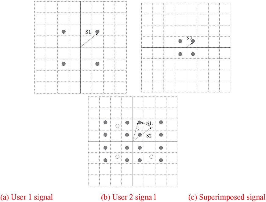
Figure 1 Overlay coding under two NOMA users.
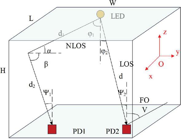
Figure 2 Transmission model of indoor visible light channel.
The visible light signal emitted from LED radiates outward with LED as the center. In this process, the visible light signal will reach the receiving end through direct light, first-order reflection, second-order reflection and other multiple reflections. The indoor propagation path of visible light signal is shown in Figure 2, including Line of Sight (LoS) and Non Line of Sight (NLoS). In LoS channel, the visible light signal reaches the receiver directly without any obstacles, and its energy loss is small. The energy of the received signal is only determined by the distance between the light source and the receiving end. In NLoS channel, visible light signal will arrive at the receiver through first-order or multi-order reflection, and its energy loss is large, and the received signal is easily affected by multipath effect, resulting in intersymbol interference. However, due to the complex propagation path of light, the proportion of first-order reflection and multi-order reflection in the total impulse response of the channel is low, and the power reaching the receiving end is small, which can be ignored. Therefore, only LoS channel is considered in this paper. If the indoor LED light source is assumed to conform to Lambert radiation model, the channel gain of direct link can be expressed as [19]:
| (2) |
In the above formula, and represent the electro-optic conversion efficiency of LED and the photoelectric conversion efficiency of PD, respectively. represents the gain of the transimpedance amplifier. represents the distance between the transmitting end and the receiving end, and represents the Lambert radiation order, which can be obtained by the formula . Among them, and represent the radiation angle of the transmitting end and the incident angle of the receiving end receiver, respectively, and represents half of the opening angle of the transmitting end. represents the gain function of the optical concentrator, and its formula is as follows:
| (3) |
Among them, represents the reflectivity, represents the angle of view of the photodetector, and represents the physical area of the signal received by the photodetector. At the receiving end, the signal received by user can be expressed as:
| (4) |
Among them, represents the channel gain u of user i, and is additive white Gaussian noise with 0 mean and variance .
SIC detects multiple access interference from other user information step by step in a certain detection sequence, eliminates it in turn, and finally demodulates its own useful signal, as shown in Figure 3.

Figure 3 Principle of SIC receiver.
The detection order is determined according to the channel gain of the user. Among them, users with poor channel quality will be allocated larger transmission power at the sending end, and will be demodulated first at the receiving end. In this paper, we assume that the user channel gain satisfies , that is, the demodulation order of the user is . If it is assumed that the -th receiver needs to demodulate the -th user signal, the receiver first demodulates the signal of the user according to the demodulation sequence, and eliminates it from the received signal to obtain . After that, the signals of other users are regarded as noise, and the signals of the user are demodulated, then the Signal Noise Radio (SNR) of the -th signal is expressed as [20]:
| (5) |
Among them, is the noise power. Next, taking two users as examples, the steps of SIC detection signal are introduced in detail.
(1) Signal detection of edge signal (U1): The signal received by U1 is:
| (6) |
Step 1: Minimum Mean Squared Error (MMSE) algorithm is used to detect:
| (7) |
Among them, is the detection matrix.
Step 2: The estimated signal is normalized:
| (8) |
(2) Signal detection of near-end user (U2): The signal received by U2 is:
| (9) |
Thereafter, the SIC is used to detect the signal:
Step 1: A strong NOMA user signal U1 is estimated, and where represents a signal that has not been demodulated and channel decoded.
Step 2: The interference signal f is demodulated, decoded and re-encoded, modulated into , thereby reconstructing the interference signal;
Step 3: The U2 received signal eliminates the interference signal and normalizes the energy of the remaining received signal:
| (10) |
Step 4: MMSE detection is carried out on the U2 signal, and the estimated signal of U2 is:
| (11) |
Step 5: is demodulated and channel decoded to recover the desired U1 signal. SIC receiver has low implementation complexity and excellent performance compared with traditional signal receivers. However, its complexity is proportional to the cubic of the number of users in the system. When the number of users is large, the decoding complexity will increase dramatically, which can not guarantee the correctness of decoding.
Physical layer security performance index is a quantitative expression to measure the security of communication system from the perspective of information theory. For different eavesdropping scenarios, security performance index often has different expression forms, so physical layer security performance should be analyzed according to the channel conditions of eavesdroppers and legitimate receivers.
(1) The security capacity is obtained through the eavesdropping channel model, and the proposed eavesdropping channel model is shown in Figure 4:

Figure 4 Wyner eavesdropping channel model.
Among them, , , and respectively represent message symbols, transmission symbols, legal reception symbols and eavesdropping symbols. In this model, the eavesdropper’s eavesdropping mode is considered as passive eavesdropping, and the legal channel and eavesdropping channel are assumed to be discrete channels. The eavesdropper’s uncertainty of the received symbol is defined as the Equivocation Rate, which is expressed as:
| (12) |
Among them, is the entropy function, and . The greater the suspicion rate of eavesdroppers, the smaller the amount of information obtained, and the higher the safety performance of the system. When gets the maximum value, , that is, the sends of the receiving symbol of the eavesdropper and the sending symbol of the source node are completely independent. The amount of information received by the eavesdropper is 0, and any useful information of the sending end cannot be obtained. The system reaches a complete confidential state. The reachable security rate is defined as if there is a coding scheme such that is reachable in the fully secure state, then the information rate at this time is the reachable security rate, and its maximum value is the security capacity. Secure capacity is one of the commonly used physical layer security metrics, which is to meet the coding efficiency when the legitimate receiver can recover the information sent by the sender and these messages are useless at the eavesdropper, that is, the secure channel capacity can be expressed as the difference between the legitimate channel capacity and the eavesdropper channel capacity. Security capacity can be expressed as:
| (13) |
Among them, and are the channel capacity of legal channels and eavesdropping channels, respectively. ergodic channel secrecy capacity and channel status are closely related. If the channel status is relatively stable, the system will have a stable security performance. Ergodic secrecy capacity is proposed as a physical layer security performance index under random channels. It is defined as the maximum safe capacity of the transmitted signal after sufficient channel implementation, and its expression is:
| (14) |
Among them, and represent the instantaneous SNR of the legal and eavesdroppers, and and represent the corresponding distribution functions.
(3) Security outage probability: For delay-sensitive services, such as voice and video calls, the traversal security energy index cannot be used to measure their security performance. Therefore, a security outage probability index based on probability theory is proposed, which can better reflect the security of delay-limited systems. The security outage probability is defined as the probability that the security capacity is less than the target security rate , and its expression is:
| (15) |
The basic eavesdropping model of NOMAVLC system consists of a sender, two legitimate NOMA users and a malicious eavesdropper. In this model, the sender sends private information to legitimate NOMA users, and the eavesdropper’s goal is to intercept the information transmitted between the sender and legitimate users. Based on this eavesdropping model, the physical layer security performance of NOMAVLC system is introduced below. In the NOMAVLC eavesdropping model, we assume that the user’s channel gain satisfies , and the user signals and satisfy the mean value of 0 and the variance of , and and are statistically independent. Considering the material limitation and safety of light emitting devices, VLC system should be harmless to human eyes and skin while communicating, and the amplitude of transmitted signal should be limited to . Among them, A is the maximum signal amplitude allowed by LED. Therefore, the received signal of the user can be expressed as:
| (16) | ||
| (17) |
In the above formula, and represent additive white Gaussian noise at user 1 and user 2, respectively, and satisfy independent and identical distribution . The signal received by the eavesdropper can be expressed as:
| (18) |
Among them, . When the channel gain of NONA user 1 is smaller than the channel gain of eavesdropping user, the security performance of legitimate user link is seriously degraded, and its security capacity is 0. Conversely, when , the secure channel capacity of User 1 can be expressed as:
| (19) | ||
Among them, and represent mutual information and entropy operators respectively. However, due to the particularity of the transmitted signals and , it is difficult to obtain an analytical solution of the above-mentioned secure capacity expression. According to the distribution characteristics of different input signals, formula (19) can be scaled by using methods such as entropy power inequality and dual solution, and the original problem can be transformed into an inequality problem that is easy to solve, thus obtaining the upper and lower bounds of safe capacity. The lower limit of safe capacity can be obtained by solving the lower limit of the first and fourth terms and the upper limit of the second and third terms of formula (19). Based on this idea, the lower limit expression of safe capacity obtained by using entropy power inequality is:
| (20) |
Among them, represents the variance operator. At the sending end, we can improve the safe channel capacity of users by means of pre-coding and artificial noise, and realize the safe transmission of information.
2.2 Algorithm Model
The downlink NOMA VLC (Non orthogonal multiple access VisibleLightCommunication) system model of colluding eavesdroppers is shown in Figure 5.
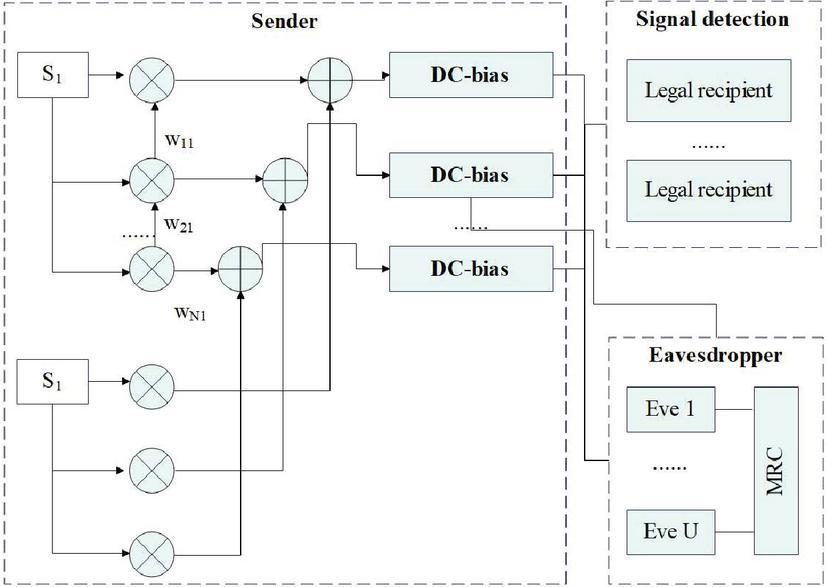
Figure 5 Downlink NOMA VLC system model of collusive eavesdropper.
In the downlink NOMAVLC system shown in Figure 5, the system includes N senders, K legitimate receivers (Bobs), and U eavesdroppers (Eves). The system employs a pre-coding scheme in which the pre-coding matrix is assumed to be , and the transmitted signal can be expressed as:
| (21) |
Among them, and are signal transmission vectors, satisfy a mean value of 0 and a variance of , and is independent of each other and identically distributed. At the same time, in order to ensure that the LED can work in the linear region, the signal amplitude should be limited to , and is the maximum signal amplitude allowed by LED.
If the legal channel matrix of Bobs is assumed to be , and satisfies , the received signal of the -th legal user can be expressed as:
| (22) |
Among them, is additive white Gaussian noise with mean value of 0 and variance of . Similarly, if the eavesdropping channel matrix of Eves is assumed to be , the received signal of eavesdropper may be expressed as . The collusion of eavesdroppers is reflected in the fact that multiple eavesdroppers can jointly detect signals. In this paper, we assume that multiple eavesdroppers use Maximum Ratio Combining (MRC) technology to jointly detect signals in order to obtain the best signal quality. Therefore, the output signal of joint detection by colluding eavesdroppers can be expressed as:
| (23) |
Among them, is the weight vector under MRC.
In NOMA system, SIC is used to demodulate the received signal of users. According to SIC principle, a user will demodulate and reject the user’s signal in sequence according to the demodulation order until this user signal is demodulated. In this paper, it is assumed that the demodulation order of user signals is . It is worth noting that the demodulation order of user signals is related to channel gain and pre-coding matrix. Therefore, in order to ensure the demodulation order of the user signal, should satisfy:
| (24) |
Among them, . However, when users use SIC technology, once the demodulation of a certain user goes wrong, it will lead to error propagation, which will make all the subsequent signal demodulation go wrong. In order to avoid this situation, it is necessary to limit the Signal To Interference Plus Noise Ratio (SINR) of the demodulated signal. In this paper, it is assumed that the SIC technique without error propagation can be realized when the SINR of the signal satisfies the following condition
| (25) |
Among them, represents the signal-to-interference ratio of signal when demodulated at , and is the threshold of .
3 Construction and Testing of Model
Because the distribution communication network is mostly built with the primary line of distribution network or rebuilt with the pipeline and overhead resources of the existing primary line, the topology structure of distribution communication network scheme should be suitable for the primary grid structure of distribution network.
The realization modes of distribution automation include remote centralized and local distributed. Moreover, the system structure consists of distribution automation system master station, distribution automation system substation (optional), distribution automation terminal (FA) and communication network. It mainly realizes the collection and control of equipment information such as switch station, ring network cabinet, box-type substation, switch on column and transformer on column. A typical distribution automation system structure is shown in Figure 6.

Figure 6 Typical structure of distribution automation system.
Cloud computing platform mainly divides a large task into several small fragments, and processes them in turn according to different fragments, thus saving the time for comprehensive processing of large tasks and reducing the difficulty of processing. The working principle is shown in Figure 7. In the cloud computing platform, multiple nodes are processed synchronously through optical communication state identification, which can more effectively improve the speed of optical communication state identification data. The steps of identifying features are as follows: (1) With the help of special tools, the optical communication status signals are collected. (2) Wavelet transform is selected to decompose the optical communication state signal in a multi-scale way, and the obtained signal is expressed in different amplitudes. (3) Data energy characteristics are unified.
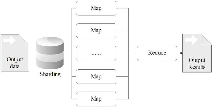
Figure 7 Schematic diagram of working principle of cloud computing platform.
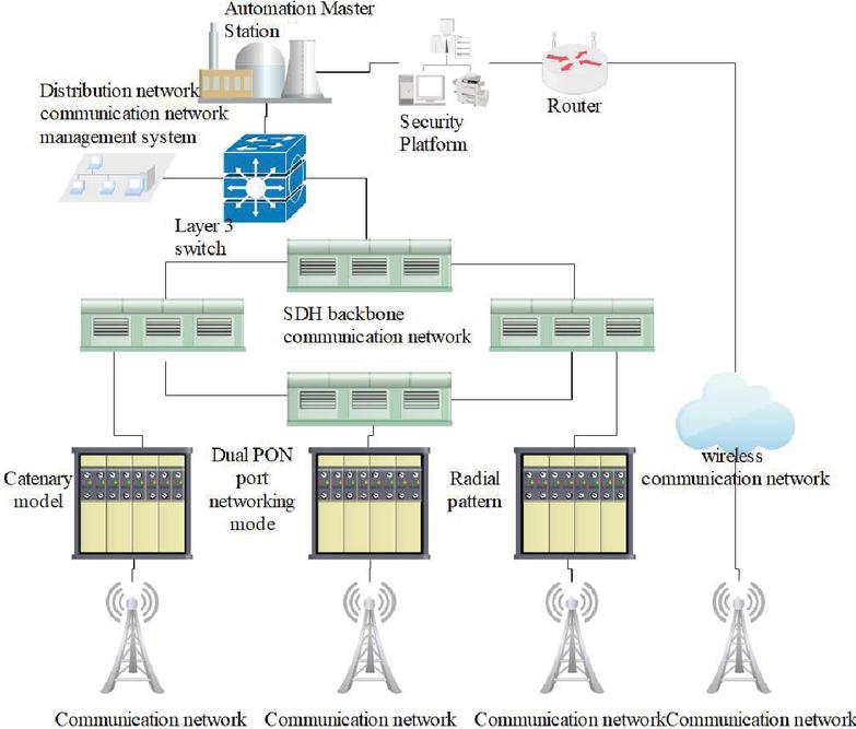
Figure 8 Communication network topology diagram of distribution automation system.
The distribution automation system realizes the full coverage of data acquisition and monitoring of distribution lines and equipment (Figure 8), and further improves the efficiency and accuracy of distribution network fault handling. Terminals are divided into “two remote” terminals and “three remote” terminals. Among them, the “three remote” terminals upload telemetry, remote communication and remote control information to the distribution automation master station. The “two remote” terminal uploads telemetry and remote communication information to the distribution automation master station. Moreover, the distribution automation master station is set up in each city company, and the optical communication network provides a channel for the information transmission of the “three remote” terminals. Distribution communication network generally adopts EPON mode, which collects the distribution automation service information of each terminal to the substation, and then provides the transmission channel to the municipal company by the backbone communication network. The information of “two remote” terminals is generally transmitted by wireless public network, so its bandwidth is not listed in this paper.
A virtual private IP network from the distribution master station to each substation is constructed through the core, switch and convergence switch carried on SDH (Synchronous Digital Hierarchy) network in the master station and substation, and the designed bandwidth from each substation to the master station is not less than 10M, and the private port is used for transmitting distribution automation information. The network architecture is shown in Figure 9.
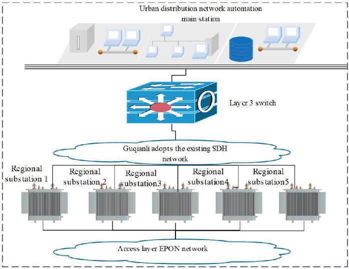
Figure 9 Construction scheme of communication network from distribution master station to substation.
The experimental simulation system in this article is mainly developed based on JADE and Java platforms. The JADE platform mainly provides an Agent design environment. During the design process, the simulation system in this article is designed as a plugin, through which the application system can build a secure communication environment between Agents. SAISCF is designed using the multi-agent framework in JADE, and its data model and communication protocol design comply with the standard IEC61850.
In order to test the performance of the power grid information dispatching model designed in this paper in optimizing power grid configuration and improving power grid load, simulation experiments are carried out. The simulation parameters are set as shown in Table 1.
Table 1 Setting of simulation parameters
| Parameter | Parameter Value | Unit |
| Operating frequency of smart grid | 20 | MHz |
| Channel bandwidth of cloud computing | 20 | MHz |
| Subcarrier number | 25 | Number |
| Sampling interval of power grid information flow | 0.5 | MHz |
| Autocorrelation matching period | 3.2 | s |
| Protection interval of overload in power grid | 1 | s |
| Carrier frequency | 5.5 | kHz |
| Modulation mode of optical communication | 4 | QAM |
| Modulation mode of optical communication | 25 | Mbits/s |
According to the above simulation environment and parameter settings, simulation analysis of smart grid information dispatching model under cloud computing and optical communication is carried out. Figure 10 shows the sampled time domain waveform of power grid information transmission. The multipath component information recombination method is used to reconstruct the information feature space of smart grid under optical communication network, and the impulse response of power grid information transmission is calculated. The results are shown in Figure 2.
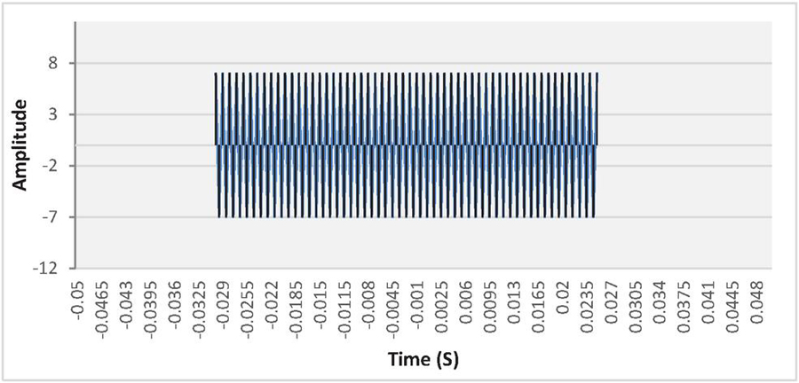
Figure 10 Time domain waveform used in power grid information transmission.
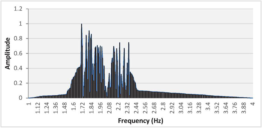
Figure 11 Impulse response calculation of power grid information.
From the above analysis, it can be seen that when the method proposed in this paper is used for smart grid information dispatching under optical communication network, it has wide broadband impulse response, which shows that it can improve the load capacity of power grid transmission dispatching.
On this basis, the method proposed in this paper is used to test the network security of smart grid. The carrier frequency of grid intrusion is 12kHz, the duration of network fluctuation intrusion is 12s, and the intrusion data comes from KDDCup2015 virus database in Web network. The channel model of optical communication network transmission is divided into two groups: channel model 1 and channel model 2. The simulation experiment is set to 18s, and the data sampling time domain waveform and intrusion detection results of power grid optical communication channel under virus invasion are shown in Figure 12(a) and 12(b) below, respectively.
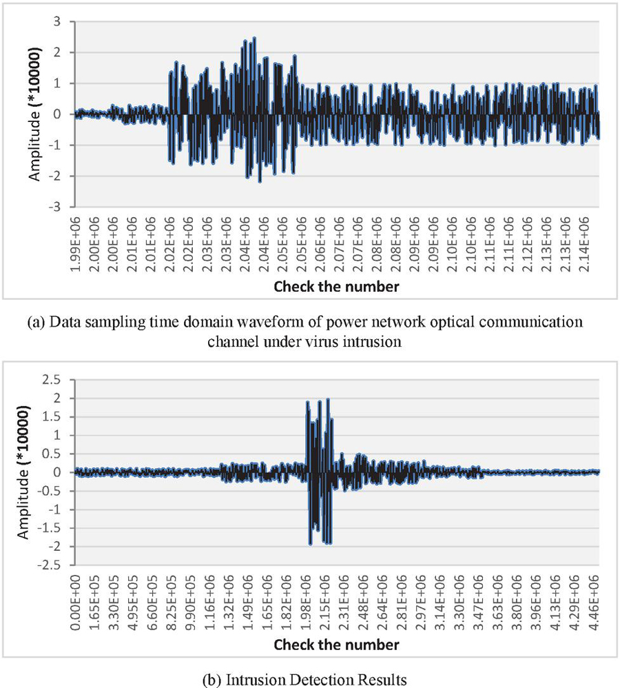
Figure 12 Optical communication network security test of smart grid.
Through the above analysis, it can be seen that in the complex data ripple of power grid optical communication channel (Figure 12a), the communication method proposed in this paper can accurately identify the intrusion factors and obtain the intrusion detection graph shown in Figure 12(b). Therefore, using this method for smart grid optical communication network intrusion detection in cloud computing environment can effectively detect intrusion data, and implement filtering processing, which improves the security of smart grid optical communication network.
Due to experimental conditions and time constraints, there are still some areas that need to be improved or further in-depth research in this study, which will be left for further study in the future In the study of error rate performance in this article, only the case where both users use 4-QAM has been considered, and in practice, there may be situations where multiple users use higher-order modulation methods for access. Therefore, studying how to further improve the reliability of transmission in this situation will have important practical significance.
4 Conclusion
In smart grid visible light communication, signals are exposed to the air and are easily intercepted by eavesdroppers. Traditional encryption algorithms achieve confidentiality by improving the computational complexity of eavesdroppers. If the eavesdropper’s computing power is limited, the encryption algorithm of encryption key will play a certain role in secrecy. However, in the future, the emergence of quantum computers with powerful parallel computing capabilities makes the traditional key scheme no longer reliable. At the same time, without the limitation of eavesdropper’s computing power, optical communication security technology based on channel characteristics has become a solution to ensure secure communication. Based on this, this paper combines intelligent cloud computing technology to build the network security system of power grid optical communication. In order to test the performance of the power grid information dispatching model designed in this paper in optimizing power grid configuration and improving power grid load, simulation experiments are carried out. Through the analysis of the experimental results, we can see that in the complex data ripple of optical communication channel, the communication method proposed in this paper can identify the intrusion factors accurately, and get the intrusion detection graph to identify the attack factors. Therefore, the method proposed in this paper can effectively improve the security of smart grid optical communication network
References
[1] Aguado, A., Lopez, V., Lopez, D., Peev, M., Poppe, A., Pastor, A., … and Martin, V. (2019). The engineering of software-defined quantum key distribution networks. IEEE Communications Magazine, 57(7), 20–26.
[2] Aguado, A., Lopez, V., Martinez-Mateo, J., Peev, M., Lopez, D., and Martin, V. (2018). Virtual network function deployment and service automation to provide end-to-end quantum encryption. Journal of Optical Communications and Networking, 10(4), 421–430.
[3] Guan, M., Yang, X., and Hu, W. (2019). Chaotic image encryption algorithm using frequency-domain DNA encoding. IET image processing, 13(9), 1535–1539.
[4] Huang, Q., Liu, D., Chen, Y., Wang, Y., Tan, J., Chen, W., … and Zhu, N. (2018). Secure free-space optical communication system based on data fragmentation multipath transmission technology. Optics express, 26(10), 13536–13542.
[5] Jiang, N., Zhao, A., Xue, C., Tang, J., and Qiu, K. (2019). Physical secure optical communication based on private chaotic spectral phase encryption/decryption. Optics letters, 44(7), 1536–1539.
[6] Karinou, F., Brunner, H. H., Fung, C. H. F., Comandar, L. C., Bettelli, S., Hillerkuss, D., … and Poppe, A. (2018). Toward the integration of CV quantum key distribution in deployed optical networks. IEEE Photonics Technology Letters, 30(7), 650–653.
[7] Ke, J., Yi, L., Xia, G., and Hu, W. (2018). Chaotic optical communications over 100-km fiber transmission at 30-Gb/s bit rate. Optics letters, 43(6), 1323–1326.
[8] Liang, X., Zhang, C., Luo, Y., Wang, X., and Qiu, K. (2022). Secure encryption and key management for OFDM-PON based on chaotic Hilbert motion. Journal of Lightwave Technology, 41(6), 1619–1625.
[9] Mehic, M., Niemiec, M., Rass, S., Ma, J., Peev, M., Aguado, A., … and Voznak, M. (2020). Quantum key distribution: a networking perspective. ACM Computing Surveys (CSUR), 53(5), 1–41.
[10] Pirandola, S., Andersen, U. L., Banchi, L., Berta, M., Bunandar, D., Colbeck, R., … and Wallden, P. (2020). Advances in quantum cryptography. Advances in optics and photonics, 12(4), 1012–1236.
[11] Sultan, A., Yang, X., Hajomer, A. A., and Hu, W. (2018). Chaotic constellation mapping for physical-layer data encryption in OFDM-PON. IEEE photonics technology letters, 30(4), 339–342.
[12] Wengerowsky, S., Joshi, S. K., Steinlechner, F., Zichi, J. R., Dobrovolskiy, S. M., Van der Molen, R., … and Ursin, R. (2019). Entanglement distribution over a 96-km-long submarine optical fiber. Proceedings of the National Academy of Sciences, 116(14), 6684–6688.
[13] Yazdeen, A. A., Zeebaree, S. R., Sadeeq, M. M., Kak, S. F., Ahmed, O. M., and Zebari, R. R. (2021). FPGA implementations for data encryption and decryption via concurrent and parallel computation: A review. Qubahan Academic Journal, 1(2), 8–16.
[14] Zhang, W., Zhang, C., Chen, C., and Qiu, K. (2017). Experimental demonstration of security-enhanced OFDMA-PON using chaotic constellation transformation and pilot-aided secure key agreement. Journal of Lightwave Technology, 35(9), 1524–1530.
[15] Zhang, W., Zhang, C., Chen, C., Zhang, H., and Qiu, K. (2017). Brownian motion encryption for physical-layer security improvement in CO-OFDM-PON. IEEE Photonics Technology Letters, 29(12), 1023–1026.
[16] Zhang, Z., Luo, Y., Zhang, C., Liang, X., Cui, M., and Qiu, K. (2022). Constellation Shaping chaotic encryption scheme with controllable statistical distribution for OFDM-PON. Journal of lightwave technology, 40(1), 14–23.
[17] Zhao, A., Jiang, N., Liu, S., Zhang, Y., and Qiu, K. (2021). Physical layer encryption for WDM optical communication systems using private chaotic phase scrambling. Journal of Lightwave Technology, 39(8), 2288–2295.
[18] Zhao, J., Liu, B., Mao, Y., Ullah, R., Ren, J., Chen, S., … and Shen, J. (2020). High security OFDM-PON with a physical layer encryption based on 4D-hyperchaos and dimension coordination optimization. Optics Express, 28(14), 21236–21246.
[19] Song, H., Fang, X., and Fang, Y. (2016). Millimeter-wave network architectures for future high-speed railway communications: Challenges and solutions. IEEE Wireless Communications, 23(6), 114–122.
[20] Liu, L., Tao, C., Qiu, J., Chen, H., Yu, L., Dong, W., and Yuan, Y. (2012). Position-based modeling for wireless channel on high-speed railway under a viaduct at 2.35 GHz. IEEE Journal on Selected Areas in Communications, 30(4), 834–845.
Biographies

Zhefeng Li graduated from China University of Political Science and Law. At present, the main research directions are: big data and artificial intelligence, power Internet of Things.

Botao Hou, Senior Engineer of State Grid Hebei Electric Power Research Institute, and Master’s degree in Computer Science and Technology from North China Electric Power University. The current research interests are focused on information and communication technology, network security, and artificial intelligence.

Xiaojun Zuo holds a Master’s degree in Computer Technology from Tianjin University. Current research interests are focused on network security technology, big data technology, and artificial intelligence technology.

Yuling Guo, Senior Engineer of State Grid Hebei Electric Power Research Institute, and Master’s degree in Computer Technology from North China Electric Power University. The current research interests are focused on software testing, information security, information operation and maintenance, etc.

Jianchun Zhou, Testing Engineer at China Electric Power Research Institute, Bachelor’s degree from Hunan University of Science and Technology. The main research areas are information systems, communication equipment detection, and network security technology.
Journal of Cyber Security and Mobility, Vol. 13_4, 605–632.
doi: 10.13052/jcsm2245-1439.1342
© 2024 River Publishers