Vulnerability Assessment and Experimentation of Smart Grid DNP3
Received 15 March 2016; Accepted 30 March 2016;
Publication 29 June 2016
Ihab Darwish*, Obinna Igbe and Tarek Saadawi
City University of New York, City College, USA
*Corresponding Author: idarwish@ccny.cuny.edu
Abstract
Smart-grids security is becoming a challenging research area that has emerged in recent years facing the energy sector. Threats are arising every day that could cause great scale of damages in critical infrastructure. Our paper will assess vulnerabilities pertaining to internal security threats associated with the smart grid. We will perform penetration testing using various attack scenarios in a simulated virtual environment involving DNP3 protocol. Vulnerability analysis and penetration testing involving Man-in-the-middle (MITM) attack will be addressed. Ultimately, by utilizing theoretical modeling of smart-grid attacks using game theory, we will be able to optimize our detection and mitigation strategies to reduce cyber threats in DNP3 environment. Intrusion detection system (IDS) will be necessary to identify attackers targeting the smart grid infrastructure. Mitigation techniques will ensure a healthy check of the network. Performing DNP3 vulnerabilities assessment, security attacks, detections, preventions and counter measures will be our goals to achieve in this research paper.
Keywords
- Smart-Grid
- SCADA
- DNP3
- IED
- Malicious Attacks
- MITM
- DoS
- Game Theory
1 Introduction
Security concerns in the energy sector will be our key driver and the smart-grid technologies will be our primary focus in this research paper. Physical and cyber security are using both physical and cyber components integrated with both legacy systems and new technologies running over TCP/IP platform [1]. Legacy Supervisory Control and Data Acquisition (SCADA) [2, 3] were initially designed to be isolated systems that had both dedicated and separate communication links and therefore cyber or physical security was never considered to be a threat. Today’s systems [1] and [4–6] demand a much higher level of communication to be available in smart-grid automation systems involving components like Intelligent Electronic Devices (1IED’s). IEDs [7, 8] are designed to automate protection, control, monitoring and metering for the smart grid system in both peer-to-peer and client server implementation.
According to [9–11], SCADA based implementation is using several standards and protocols developed over the years to enable data communication in Industrial Control Systems (ICS) including the smart grid. MODBUS [12, 13], DNP3 [14, 15] and the latest IEC 61850 [17, 18] are considered to be the most popular ones. Distributed Network Protocol (DNP3) as our main focus in this research paper, is an IEEE-1815 standard and the primary protocol being deployed in smart-grid systems and other utility providers. It is considered to be the predominant SCADA protocol in the US energy sector.
DNP3 is a reliable and efficient protocol used in the delivery of measurement data from an outstation or slave located in the field to a utility master operating in the control center. Control requests are made from the master to the outstations by an operator or by using an automated process in addition to other activities like time synchronization, file transfer and other related tasks. Therefore, it is very critical to study the protocol’s behavior and its application in real-time implementations. Taxonomy of attacks were identified in [19] and the recent publication of [20] that shows many deficiencies and vulnerabilities in DNP3 including 28 generic attacks. Related SCADA attacks were also studied using techniques including fault trees, attack trees and risk analysis [21] that provided more theoretical approach as opposed to our method that is more specific to DNP3 and based on using a combination of experimental and theoretical techniques to complement the conceptual analysis.
Our approach consists of carrying out four primary tasks starting with reviewing DNP3 and performing vulnerability assessment to identify and to evaluate potential threats associated with smart grid DNP3 implementations. We will setup a basic smart-grid testbed experiments using virtual environment to analyze vulnerabilities and to perform penetration testing. Various attack scenarios will be evaluated including denial-of-service (DoS) and man-in-the-middle (MITM) type of attacks to identify possible threats associated with the smart grid. Also, by utilizing theoretical modeling of smart-grid attacks using game theory, we can further analyze the outcomes of MITM in DNP3 environment. Ultimately this will lead us to the use of intrusion detection system (IDS) that will be necessary to identify attackers targeting different part of the smart grid infrastructure and we can apply mitigation strategies to ensure a healthy check of the network.
Our research paper will have four primary objectives as follows:
- Review the security threats in DNP3 based smart-grid infrastructures.
- Perform several attack experiments including DoS and MITM to show vulnerabilities in DNP3 implementation using Opendnp3 platform as a prototype environment.
- Use “Game Theory” to model man-in-the-middle (MITM) attack in DNP3 environment, analyze detection strategies, mitigations and perform Nash Equilibrium analysis.
- Establish the pass and drop mitigation technique to reduce the impact of MITM attacks along with the selection of the retransmission timer.
Section two of this paper will address the DNP3 protocol stack and the security threats. In the third section, four attacks scenarios will be presented in more details using DNP3 prototype model. Theoretical modeling using game theory will be analyzed in section four, detection and mitigation analysis will follow in section five along with our conclusion.
2 Security Threats in DNP3 Environment
DNP3 [14, 15] is an open standard that can be deployed using several topologies including point-to-point (one master and one outstation or slave), multi-drop topology (one or multiple masters and multiple outstations) or using the hierarchical layout where systems are arranged in a tree like setup and the outstation could act as both a slave to a DNP3 master or a master to other outstations.
2.1 The DNP3 Protocol Stack
DNP3 messages [19] can be mapped to the upper layers of the OSI model and are based on three layers as shown in “Figure 1”: data link, pseudo-transport and application layers where AH, TH and LH respectively denote Application Header, Transport Header and Data Link Header. If a DNP3 data stream will be sent over a LAN/WAN, it will be constructed from the three main DNP3 layers and then will be encapsulated in the Transmission Control Protocol (TCP) by the transport layer, which in turn is encapsulated in the Internet Protocol (IP) layer.

Figure 1 DNP3 Protocol Stack.
The DNP3 data link packet header (LH), “Figure 2”, consists of a fixed size of 10 bytes long header block referred to as block 0, followed by 282 bytes long data portion divided into 16 bytes blocks; block 1 to block 16. Each block ends with two bytes of CRC code with a total of 32 bytes. The link header (LH) is split into a two bytes “sync” field for synchronizing the receiver and the transmitter, a one byte length field that specifies number of bytes in remaining fields (with the exception of the CRC length), a one byte control field, two bytes for each of source and destination addresses, and finally a 2-bytes CRC [22, 23].
2.2 DNP3 Attack Model
To set up the prototype infrastructure to perform the attack scenarios including DoS and MITM type of attacks, three Linux nodes are used to run in a virtualization environment. The Master (M) and the Outstation or Slave (S) are both running Ubuntu operating system [24] with OpenDNP3 protocol [25] and are exchanging dnp3 request and response packets. The attacker node (A) is also running Ubuntu and with the help of Ettercap [26] tool, it is configured to be in the middle of the communication between the master and the outstation.
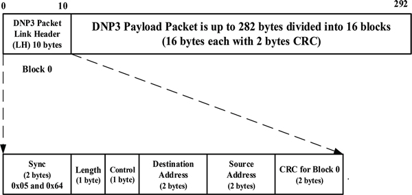
Figure 2 DNP3 Packet Blocks.
Figure 3, below shows the state transition diagram representing a specific attack scenario by the attacker (A) to stop the slave (S) from sending unsolicited messages to the master (M). The attacker is performing packet intercepting and packet injection.
2.3 Attack Categories – Scenarios
To perform security penetration in DNP3 environment, four possible attack scenarios are discussed as follows:
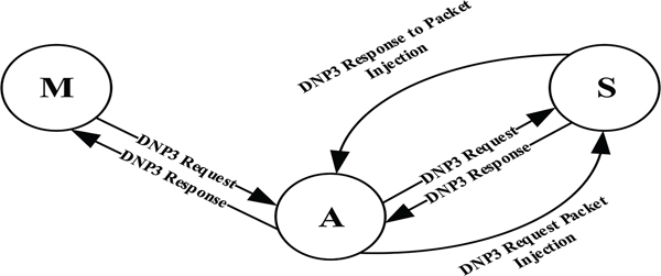
Figure 3 MITM Attack State Diagram 1.
1) Man-in the-Middle (MITM) Attack – Sniffing Generated Traffic from the Slave and Master nodes
Sniffing or capturing the traffic passing between the master and the slave nodes is handled by using man-in-the-middle attacker node. Ettercap tool on the Attacker node was used to perform the attack by adding both master and slave IP addresses to the target list, and then Address Resolution Protocol (ARP) poisoning was initiated, and the sniffing option was selected.
2) Blackhole Attack (Packets Drop Attack) and Selective DNP3 Packets Dropping Attack
Packets drop attack or blackhole attack is considered to be a type of denial-of-service attack in which all packets passed through the attacker are discarded instead of passing through to reach their destination. In packets dropping attack, packets are routinely and selectively dropped that makes it even harder to detect and to prevent.
3) DNP3 Packets Modification and Injection Attacks
Packets modification is the process of altering the content of a specific DNP3 payload using predefined filters. Payload is modified and replaced with a new one. Here the attacker tries to manipulate DNP3 packets by imposing changes to the exchanged packets. Actually the attacker will capture one of the exchanged packets from the source to the destination and will apply modification to the DNP3 payload in order to portray different message to the destination. Injection of a totally new packet is also a possibility in this category.
4) Denial of Service (DoS) Attack
Denial of Service (DoS) attack is an attempt to make a machine or a network resource unavailable to its intended users, such as to temporarily or indefinitely interrupt or suspend services of a host connected to the network.
Our next section we will provide more experimentation details related to performing the four mentioned categories of attacks in the prototype model discussed earlier.
3 Attack Experiments
In order to demonstrate vulnerabilities in smart-grids, we will set up a basic grid infrastructure in a virtual environment. In this section, we will simulate experiments of smart grid environment involving one master and one outstation or slave (Figure 4) for the purpose of investigating important vulnerabilities and possible insider attack scenarios using MITM. The Attacker node is connected to the same network of the Master and the Outstation nodes.
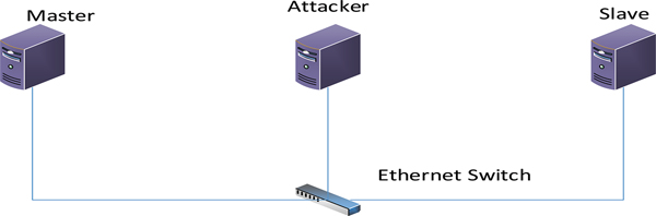
Figure 4 A cyber-attack model.
The following graphs (Figure 5 and Figure 6) show normal communication between master and outstation. Both graphs are almost identical since it’s a reflection of the same thing seen from the two different nodes, but with different time delays.
Next, we will provide more details of the attacks as follows:
1) Man-in the-Middle (MITM) Attack – Sniffing Generated Traffic from the Slave and Master nodes
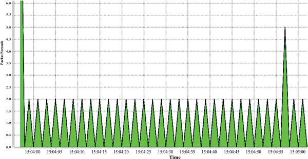
Figure 5 Packets received from the outstation as seen at the master node in packets/sec.
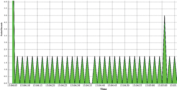
Figure 6 Packets sent from the outstation to the master node in packets/sec.
This type of attack can be categorized as a network attack, and forms the basis for other types of attacks. Although, there are many kinds of MITM attacks that exist, but we will be using the type that involves poisoning the Address Resolution Protocol (ARP) cache of the victims and it is called ARP spoofing or poisoning. To perform this attack, the first requirement will be to have the attacker node on the same network as the victims. Here, the attacker uses Ettercap to accomplish this task; a network attack tool by running the following code:
sudo ettercap -T -q -i eth3 -M ARP
/10.1.1.2/ /10.1.1.3/
Hence, any traffic passing through the network to and from the Master or the Slave node, would go through the attacker’s machine. Figure 4 depicts MITM attack performed on the attacker node against victim nodes, traffic to and from the master node passes through the attacker. If this attack is achieved, then the attacker can further perform other attacks.
The master and the outstation IP addresses are both added to the target list of the Ettercap tool, and the ARP spoofing option is selected. Notice that prior to the attack, the attacker can’t see the traffic being exchanged between the master and the outstation. The received packets/seconds by the attacker node shows blank during this period because of the fact that the network is not a broadcast and hence, nodes connected to the same switch can only see packets destined to them. Figures 7 and 8, show the traffic in packets/second as seen at the master and the outstation before and during MITM attack.
Notice the time between 15:53:35 and 15:54:42 from Figure 9, no packets are passing through the attacker node. But after initiating the MITM attack at time 15:54:42, it is shown that the outstation and the master traffic are passing through the attacker node.
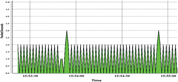
Figure 7 Generated traffic from outstation to master before and during a MITM attack as seen at the Master node.
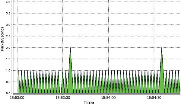
Figure 8 Traffic before and during a MITM attack as seen at the Outstation node.
2) Blackhole Attack (Packets Drop Attack) and Selective DNP3 Packets Dropping Attack
As discussed earlier in section two, packets drop attack is referred to as a blackhole attack that is considered to be a type of denial-of-service attack in which all packets passed through the attacker are routinely and selectively dropped or discarded instead of passing to reach their destination. Now, the Attacker node can view the DNP3 traffic of both victims and in order to drop the traffic generated by any of them, an Ettercap filter is created to specify the conditions to enable the selective dropping of dnp3 traffic.
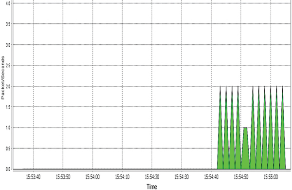
Figure 9 Traffic before and during a MITM attack as seen at the Attacker node.
If packets are selectively dropped, then this type of attack is called a gray hole attack. To perform this attack, a python script is executed by the attacker node after a successful MITM attack. The script contains the following lines of code to direct the attacker’s network interface adapter to drop all DNP3 packets to and from the Master node:
if(ip.src == '10.1.1.2' || ip.dst == '10.1.1.2'):
  if (ip.proto == TCP & tcp.dst == 20000):
   drop()
   print ("DNP3 packet to or from Master node dropped\n")
Now, in order to drop the packets generated or received by the Outstation, the following lines of code are used:
if(ip.src == '10.1.1.3' || ip.dst == '10.1.1.3'):
  if (ip.proto == TCP & tcp.dst == 20000):
   drop()
   print ("DNP3 packet to or from Outstation node dropped \n")
The above scripts identify the DNP3 packets by looking for TCP packets that has a port number of 20000 which is the DNP3 port number. Figures 10 and 11 will show the traffic before and after the attack.
According to Figure 10 below, the “black hole” attack was executed between the time 18:33:15 and 18:36:00, which corresponds to a time of 18:33:38 to 18:36:31 in Figure 11. The traffic in the middle between 18:35:00 and 18:36:04 of Figure 11 represents link status request command packets sent by the outstation to inquire of the status of the link after the “black hole” attack caused a communication breach between the two stations. Once the black hole attack was stopped by the attacking node (time 18:36:00 in Figure 10 or time 18:36:40 in Figure 11), then the two victim nodes will try to reestablish the communications as shown by the increased amount of traffic. This form of attack can really be a destructive one since the attacker can choose to redirect packets instead of dropping them. In which case, sensitive information about the grid could be stolen by the attacker for further analysis.
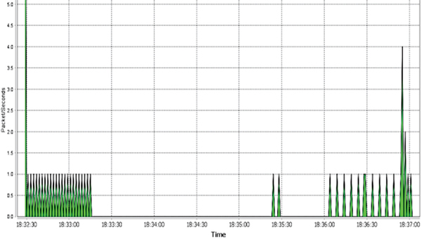
Figure 10 Packets per seconds sent from the outstation to the master as seen at the Master node – “Black Hole Attack”.

Figure 11 Packets per second sent from the outstation to the master as seen at the Outstation node – “Black Hole Attack”.
3) DNP3 Packets Modification and Injection Attacks
To manipulate the dnp3 traffic, we created a code to capture a packet instance and to check the length of the TCP before modification and replacing the contents of the payload with the modified one. A new length of the TCP packet was computed and added to the payload in addition to updating the IP length field and deleting both of the IP and the TCP checksum fields. We have used a packet manipulation program called Scapy [27] to recalculate the checksums.
Now, in order to send the modified packet, a new TCP session was initiated with the slave node listening at the dnp3 port 20000, and another hijacking technique was invoked to take over the existing TCP session. The test results showed that the attacker; by modifying the TCP/IP header and DNP3 messages, was able to manipulate, control and redirect the DNP3 traffic and even change the exchanged messages (DNP3 payload) between the master and the outstation.
To make the necessary modifications stated above, we pushed the desired DNP3 payload to our attack code using the “nfqueue” python module in combination with Linux “iptables” utility that can be used to allow or to block incoming or outgoing traffic on specific ports. This code also predicts the sequence and acknowledgment numbers of the next packet to be sent by the victim node(s). In order to inject the modified packet, the predicted sequence and acknowledgement numbers were obtained as explained in the above paragraph and are used to hijack the TCP connection. Then, Scapy program is used to inject a malicious TCP packet to the already existing TCP connection. Hence, the Slave would think that this crafted message is coming from a legitimate master. The test results showed that the attacker; by modifying the TCP/IP header and DNP3 messages, was able to manipulate, control and redirect the DNP3 traffic and even change the exchanged messages (DNP3 payload) between the master and the outstation.
Now, in order to inject a totally new DNP3 packet into the traffic stream, the filter is modified and the attacker keeps track of the exchanged traffic between the dnp3 stations and monitors the sequence numbers (SN) and the acknowledgement numbers (AN) and make the move to inject a totally new packet with newly predicted SN and AN. Also, the attacker will maintain a response to the injected packet and make sure it is dropped to prevent being detected. Attacker, then stops the MITM attack and the communication resumes between the master and the slave. Next we will show two examples reflecting the attacks.
a) Unsolicited Messages Attack Example
Unsolicited message is considered to be a way the remote terminal unit (RTU) or the outstation, can communicate certain activities or events data to the master station without being polled. Messages can be in the form of specific readings, warnings, or errors detected by the outstation that need to be sent to the master station for further and immediate actions. It is a way to ensure that current status is understood by the master station, for example unsolicited message from the RTU in a smart-grid environment can be sent to the master to indicate that the load’s requirement has decreased and it needs to be changed by the master station to a different value and the outstation will be expecting to receive the control message from the master.
In virtualization environment while normal communication is occurring between the master station and the outstation exchanging DNP3 messages encapsulated in TCP/IP packets, an attack is successfully performed to intercept the communication by stopping the outstation from sending unsolicited messages without impacting the normal communication behavior. Such an attack can lead to very disastrous situation if such penetration occurred in the smart grid network. Figure 12 shows an example of security penetration executed by the attacker to intercept the communication channel and to inject the malicious payload data without impacting the rest of the communication session.
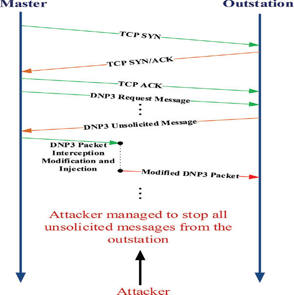
Figure 12 A cyber-attack scenario – DNP3 Unsolicited Message Attack.
b) Cold Restart Attack Example
When DNP3 “Cold Restart” request command is received by the outstation and the packet is confirmed to be originated from the master, the outstation then performs a full restart on completion of the communications sequence. The outstation will also send a reply to the master with the time the outstation is available before restarting. This attack involves sending a command called “Cold Restart” to an outstation which causes the outstation to completely restart.
After “Cold Restart” command was injected into the traffic stream from the master to the outstation, Figures 13 and 14 show that the outstation is shutting down after a duration specified by the attacker. Hence, after the time 17:22:02 (Figure 14), the outstation performed a cold restart which is apparent from the zero traffic displayed on the graph from the time of the restart. Meanwhile, the master node is still trying to communicate with the outstation (Figure 13 shows pulses after the time 17:21:31) and not knowing that the outstation is performing a cold restart.

Figure 13 Traffic in packets per second sent from the outstation node to the master node as seen at the Master node – “Cold Restart”.

Figure 14 Traffic in packets per second sent from the outstation node to the master node as seen at the Outstation node – “Cold Restart”.
4) Denial of Service (DoS) Attack
Denial of Service (DoS) attack is an attempt to make a machine or network resource unavailable to its intended users, such as to temporarily or indefinitely interrupt or suspend services of a host attached to the network. To perform this attack, hping3 is installed in the attacker node which is a tool for DoS and distributed-DoS attack. Below is the command that was executed by the attacker.
sudo hping3 -c 1000000 -d 120 -S -w 64 -p
20000 --flood --rand-source 10.1.1.2
The above command would flood port 20000 (DNP3 port) of the outstation node (10.1.1.2) with 1000000 packets (with body size of 120 bytes) that have randomly generated (spoofed) IPs. Figures 15 and 16 show the outcomes of running this attack.
According to Figures 15 and 16 below, and once the attack was initiated, the outstation gets huge amount of fake DoS traffic (time 13:22:44 of Figure 16 (a) or 16 (b) which causes the commands or responses sent by the master not to be processed by the outstation. Hence, the blank space is shown at the master (Figure 15) between 13:22:44 and 13:22:58.
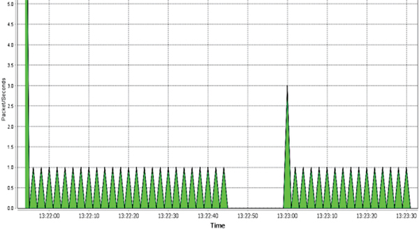
Figure 15 Packets per Second received by master from outstation as seen at the Master station.

Figure 16 (a) Packets/sec received by the Outstation as seen at the Outstation. (b) Zoomed version of Figure 16 (a).
4 Theoretical Modeling of MITM Attack
In modeling the behavior of communication between the intruder and the legitimate IED devices, game theory principles [28] can be used to establish the attack scenarios as a competition game between the attacker and the IED defender, where each side’s strategy is to maximize one’s gains. In our modeling, the game will be a non-cooperative game between the Attacker (A) and the normal nodes, Master (M) or Slave (S).
We will model each exchange of DNP3 packets between the master and the slave as a single handshaking game where the master sends a request and the slave responds with a response packet. “Figure 17”, displays an example of exchanged messages involving master (M), the slave (S) and the attacker node (A) while keeping track of the timing of each transaction. For simplicity, we are showing T1,T2 and T3 as time stamps.
In our model, illustrated in Figure 18, we will demonstrate one type of man-in-the-middle (MITM) attacks, possible strategies for each node on the network and the possible outcomes of the attack by analyzing Nash Equilibrium (NE).
4.1 Assumptions
- Each game is a single exchange of DNP3 packets between the master and the outstation.
- Each player chooses a strategy and will receive a payoff based on the selection.
- Master station will initiate the transaction by sending a DNP3 packet.
- Attacker node will intercept the packet and perform modification to the payload and sends the outstation the modified version of the original packet.
4.2 Game Setup
We will model the attack as a three node game involving non-cooperating strategies between the master and the attacker and with the communication channel (C) acting as the nature player imposing network delays that behaves stochastically.
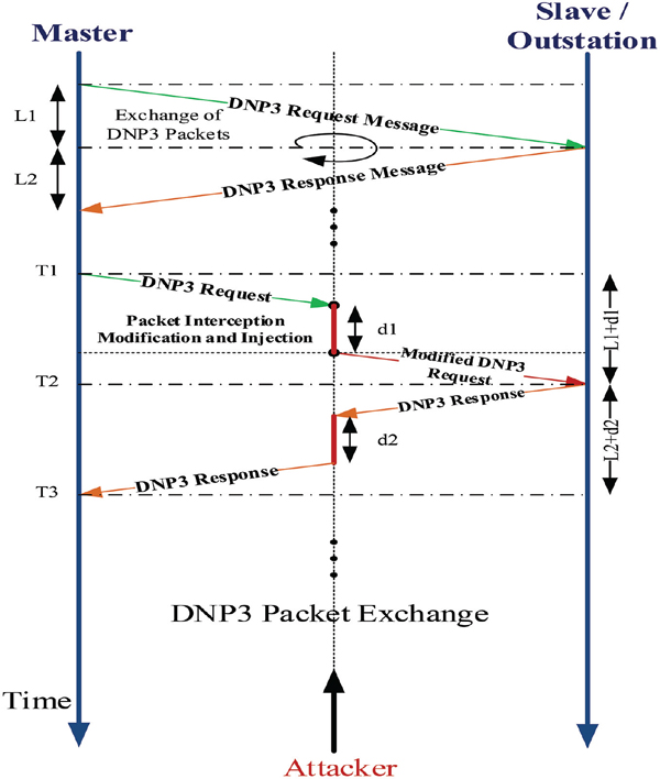
Figure 17 DNP3 Packet Exchange.

Figure 18 MITM Attack State Diagram 2.
In our analysis, we will use the master node that is generating the packet exchange and the attacker as the primary two rational non-cooperative players utilizing incomplete information but have common knowledge of the game setting including the payoffs.
Our game is sequential and starts when attacker A, acting as MITM, chooses its actions, followed by the actions of the communication channel (C) and then by the initiating node M who chooses its actions based on the time stamps and based on the outcomes of A and C’s actions. Figure 19 illustrates the game setup and actions in an extensive form with A as being the root of the tree.
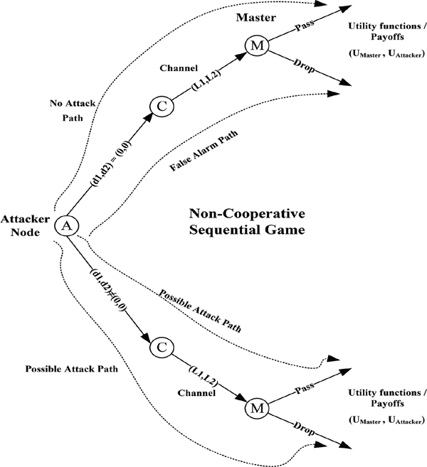
Figure 19 Game setup – Extensive form.
Attacker will be able to capture DNP3 traffic between the master and the slave and therefore can perform several type of attacks including Denial of Service (DoS), packet modification, and packet injection and so on. In Figure 17, we represented the time involved by the attacker in performing the interception and packet modification as d1 and d2 that both are real numbers and could take any value between 0 and dA.
The master node will generate the DNP3 request and will wait for the DNP3 response from the slave and can detect the attack based on the delay imposed by the attacker and will have two possible actions; either dropping the received packet or accepting it after checking the timestamps associated with this transaction (T1 to T3).
The communication channel C as the third player will have two possible decisions based on the delays in each direction of the packet exchange, L1 or L2 and are random real numbers and for simplicity we will assume that both are identical.
4.3 Pass/Drop Algorithm
During packet exchange, we can compute the round trip time delay (RTTD) based on the actual timestamps (T1 and T3) as follows:
Actually, each legitimate node on the smart-grid can be setup to calculate the round trip time delay for each DNP3 packet exchange and each node will be able to generate an average for RTTD as a baseline Trtrip. We then have the following equation:
For symmetric exchange of packets between the master and the slave, ½Trtrip will represent half the average round trip time delay for either request or response packets and Δ will represent the deviation from half of the average and if the deviation is between zero and a safety margin ΔSM then master will accept the packet otherwise, it will be dropped. Therefore, the safety margin (ΔSM) must be carefully chosen to prevent attacker from having the needed time to perform the attack.
4.4 Players’ Strategies
Root of the tree, Figure 19, represents the attacker node and each player will have a strategy set as follows:
- SMaster: Strategy set for the master node are {Pass, Drop} and will depend on the round trip time delay according to the timestamps (Equation 1)
- SAttacker: Strategy set for the attacker node, time delays (d1, d2) where: 0 ≤ d1 ≤ dA and 0 ≤ d2 ≤ dA
- SChannel: Strategy set for the communication channel, propagation delays {(L1, L2), where L1 ≥ 0 and L2 ≥ 0}
Therefore, the strategy space S will be (SMaster × SAttacker × SChannel).
4.5 Payoff Utility Functions
In our game the attacker will try to maximize its gains and the defender or the master will try to minimize its losses and we will assume that the defender has no prior knowledge of the deviation Δ and for the attack to be successful Δ must be greater than ΔSM. We introduce the following utility functions for a given strategy s = {sAttacker, sMaster, sChannel}:
The attacker will receive a payoff of 0, if the defender will choose to play “drop” to the packet, or playing “pass” strategy given that Δ, the deviation from half of the average round trip time delay ( ½Trtrip), is less than or equal to the deviation safety margin ΔSM. Attacker will gain a positive payoff Ug if the master chooses “pass” and Δ > ΔSM and in this case the attack is successful. Also, the utility will pay Uf for having the master playing safe and drop the packet when there is no attack as being a false alarm case.
In our model, there is no positive gain for the master, and the maximum achieved payoff is zero for the case the attacker is choosing a strategy sAttacker ≠ (0, 0), i.e. there is an attack and the master has managed to avoid the attack with “drop” strategy, in addition to the second case where the master chooses to pass when Δ ≤ ΔSM. This is a zero-sum game when we add the payoff utilities of both players, UAttacker(s) and UMaster(s) and for all given cases, the sum will be zero.
4.6 Game Theory Analysis
In this section we will analyze the outcomes of the two-players game modeled for DNP3 packets exchange between the master and the slave where packets are being intercepted by the attacker acting as MITM.
According to the game settings and the strategy sets for each player, both the attacker and the defender had multiple strategies to choose from. For the attacker, he will observe the defender who chooses strategy s1Master from SMaster strategy set and then the attacker will choose strategy s1Attacker from SAttacker strategy set and we represent the strategy combination as s = (s1Master, s1Attacker) ∈ S, strategy space. Now, the attacker (A) can choose a strategy to either perform the attack successfully or having unsuccessful one. If A chooses the strategy SAttacker = (d1, d2) and 0 ≤ d1 ≤ dA and 0 ≤ d2 ≤ dA, we will have the following possibilities as shown in Table 1.
The master node as being the defender will have one strategy s1Master conditioned according to the round trip time delay (RTTD) of Equation (1) and against the baseline average Trtrip. The Master node will choose a pass strategy if RTTD ≤ Trtrip + ΔSM and a drop one if RTTD > Trtrip + ΔSM. But due the nature of communication channel (C) and its stochastic nature, this strategy is not always safe as it can lead to have a false alarm to drop the packet even without having any attack.
Table 1 Game analysis – attacker and master strategy combinations
| SAttacker | SMaster | Analysis |
|---|---|---|
| (d1, d2) = (0, 0) |
Drop | Attacker chooses not to attack and Defender Drop the packet that will lead to a false alarm. Attacker in this case will gain +Uf and defender will get –Uf. |
| (d1, d2) = (0, 0) |
Pass | Attacker chooses not to attack and Defender Pass the packet and the both receives a gain of 0 as payoff. |
| (d1, d2) ≠ (0, 0) |
Pass and Δ > ΔSM |
Attacker chooses to attack from either direction and if either delays d1 or d2 is greater than safety margin ΔSM and defender chooses to pass then the attack is successful. Attacker will gain Ug and defender will have a loss of the same value. |
| (d1, d2) ≠ (0, 0) |
Pass and Δ ≤ ΔSM |
Attacker chooses to attack similar to the previous case but Δ is less than the safety margin ΔSM and the defender chooses to pass. In this case the attack is unsuccessful and both will a gain of 0. |
| (d1, d2) ≠ (0, 0) |
Drop | There is an attack and the defender plays safe with a drop strategy payoff will be 0 for both the defender and the attacker. |
4.7 Nash Equilibrium
Next, we will consider the evaluation of the Nash Equilibrium (NE) in reaching an equilibrium point(s) between the attacker and the defender that is the profile of strategies for each player in choosing the best strategy for the choices of the other player(s). Deviating from NE will not provide the best results to the players.
In our game we have two NE, the first one is reached when the defender always chooses to drop the packet irrespective of having an attack or not, this is the safe thing to do since this will lead to an equal payoff of zero and therefore both players have no interest of deviating from this equilibria. On the other hand, the attacker will not reach his goal of getting the attack done and the defender will not be able to complete the DNP3 packet exchange with the other party. Notice that if A decided to choose strategy (0, 0) not to attack and defender chooses to drop the packet that will lead to false alarm and the attacker in this case will gain +Uf and defender will get –Uf and this will not provide the defender with the best possible payoff and hence it will tend to change its strategy.
Our second NE is using the drop threshold strategy discussed in Section 4.3 and in this case the defender is choosing to pass the packet if Δ ≤ ΔSM and hence RTTD ≤ Trtrip + ΔSM and to drop it if Δ > ΔSM and RTTD > Trtrip + ΔSM. In both cases, the attacker strategy is sAttacker ≠ (0, 0) and the attack will not be successful and results will lead to an equal payoff of zero for both the defender and the attacker reaching a NE. Therefore, for this NE, the defender will optimize its drop threshold value, (Trtrip + ΔSM) to allow attack detection and to prevent from having false alarms possibly due to channel delays and hence this will yield an effective detection and mitigation strategy for the defenders. Our next section will support our analysis and results from game theory.
5 Detection and Mitigation Strategies
Intrusion Detection is the primary tool for protecting DNP3 environment from malicious behavior attempting to intercept the network, interrupting communication or manipulating data transmission. There are two types of intrusion detection, host based providing protection at the host level and network based that monitors traffic across the entire network. In our research we used the host based detection method, mitigations strategies and techniques as an attempt to prevent successful MITM attack on DNP3 environment.
In order to optimize our detection and mitigation procedures to eliminate cyber threats, we will utilize logs and machine-learning techniques such as statistical analysis to create and implement procedures for IED’s to detect cyber threats independently and/or collaboratively. Also, we can prevent attacks by implementing pattern recognition based on traffic analysis between the legitimate devices and the attacker(s). Measuring the average round trip time delay Trtrip between legitimate communicating IED nodes for each request and response packet exchange and perform dynamic adjustments to maximum allowed timeout to be equivalent to Trtrip + ΔSM, where ΔSM is a safety marginal time for the round trip as discussed in Section 4. This should prevent attackers from having enough time to initiate any attack by injecting traffic since their packets will be automatically dropped by the receiver.
5.1 Setting up the Round Trip Time Measurement
Steps for setting up the average round trip time measurement at the master or the outstation using Round Trip Timing Agent tool (RTTA developed internally):
- Establish the dnp3 session between the master and the slave.
- Compute the average dnp3 round trip time delay for dnp3 packets (Trtrip) by running the RTTA at the master and the slave.
- An output text file is generated for the duration of the runtime that contains round trip time (RTTD) for each dnp3 packet exchange.
- An Average Round Trip Time Delay (Trtrip) is calculated.
5.2 Pass/Drop Algorithm
During packet exchange between master and outstation, we will compute the round trip time delay (RTTD) for each DNP3 packet exchange and will be able to generate an average as a baseline Trtrip. We have the following equation similar to Equation 2:
Tarrival and Ttransmitted are actual time stamps for the returning packet and for symmetric exchange of packets between the master and the slave, ½Trtrip will represent half the average round trip time delay for either request or response packets and Δ will represent the deviation from the average and if the deviation is between zero and a safety margin ΔSM then the master will accept the packet, otherwise the packet will be dropped. The safety margin ΔSM, must be carefully chosen to prevent attacker from having the needed time to perform the attack. The following scenario steps show the algorithm sequence in more details:
- Each node will measure its average round trip time delay Trtrip for each exchange of DNP3 packets.
- Master sends a DNP3 packet to the outstation encapsulated by TCP with Sequence Number (SN) and Acknowledgement Number (AN) in the segment header.
- Outstation will send DNP3 response to master request.
- The master will monitor the round trip time for the received response packet and perform a comparison against Trtrip and if the deviation exceeds the safety margin, then the packet will be dropped and a retransmission will occur.
5.3 Mitigation Techniques
Mitigation techniques will follow the retransmission strategy. In [29], two events have been defined to require this strategy, damaged TCP segments in transit is the first possible event and the segment fails to arrive as the more common one. In both cases, if segment does not arrive successfully, there is a timer associated with each segment and a retransmission will occur if the timer expire before acknowledging the segment. Therefore, it is a key design issue to evaluate the timer in TCP that encapsulate DNP3 packets, timer should not be too small to cause many unnecessary retransmissions or too large to cause response delay for lost segments. The timer is variable and it should be set larger than the round trip time delay.
Now, if we consider the DNP3 packet exchanges between the master and the outstation, they will follow the same analogy and if the timer is carefully set close to the round trip delay, MITM attacks could be prevented. Hence, any delays caused by the attacker exceeding the safety margin ΔSM will trigger a retransmission to the original packet by the sender. Both, master and the outstation will use the average round trip delay calculated in Section 5.1 to adjust its retransmission timer.
6 Conclusion
In this paper we analyzed various threats and vulnerabilities in DNP3 protocol operating in SCADA based implementation as part of the smart grid using prototypes and virtual environments. Security penetration testing was performed using four primary attack scenarios including denial-of-service (DoS) and man-in-the-middle (MITM) type of attacks. In our research we were able to explore and combine both experimental analysis and theoretical modeling techniques using game theory. Nash equilibria was utilized to highlight possible outcomes of the MITM attack and to validate the pass and drop strategy that effectively can be used to detect attacks and to provide understanding to mitigation. In our last section, mitigation of attacks and attack’s prevention was explored using packet retransmission strategy and the timer was carefully set close to the round trip time delay in order to minimize the impact of various attacks. Our future work, will expand this area further by implementing real-time smart-grid network and performing more penetration testing involving the secured authentication version of DNP3 (DNP3-SA) using multiple scenarios and smart grid configurations.
References
[1] Miles H. F. Wen, Ka-Cheong Leung, Victor O. K. Li, Xingze He and C.-C. Jay Kuo (2015). A survey on smart grid communication system. APSIPA Transactions on Signal and Information Processing, 4, e5 doi:10.1017/ATSIP.2015.9
[2] C. Feltus, M. Ouedraogo and D. Khadraoui, “Towards cyber-security protection of critical infrastructures by generating security policy for SCADA systems,” Information and Communication Technologies for Disaster Management (ICT-DM), 2014 1st International Conference on, Algiers, 2014, pp. 1–8.
[3] Cyber security risk assessment for SCADA and DCS networks, ISA Trans. 2007 Oct; 46(4): 583–94. pub 2007 Jul 10.
[4] Quadrennial Technology Review 2015 Ch3: Enabling Modernization of the Electric Power System Technology Assessments – U.S. Department of Energy – http://energy.gov/sites/prod/files/2015/09/f26/QTR2015-3A-Cyber-and-Physical-Security 0 0.pdf
[5] R. Brown, “Impact of smart grid on distribution system design,” in Proc. IEEE Power Energy Soc. Gen. Meeting, 2008, pp. 1–4.
[6] P. Parikh, M. Kanabar, and T. Sidhu, “Opportunities and challenges of wireless communication technologies for smart grid applications,” in Proc. CCECS Power Energy Soc. Gen. Meeting, 2010, pp. 1–7.
[7] IEEE Standard for Intelligent Electronic Devices Cyber Security Capabilities – Redline,” in IEEE Std 1686–2013 (Revision of IEEE Std 1686–2007) – Redline, vol., no., pp. 1–49, Jan. 13 2014.
[8] D. C. Mazur, R. A. Entzminger and J. A. Kay, “Enhancing Traditional Process SCADA and Historians for Industrial and Commercial Power Systems With Energy (Via IEC 61850),” in IEEE Transactions on Industry Applications, vol. 52, no. 1, pp. 76–82, Jan.–Feb. 2016. doi: 10.1109/TIA.2015.2463792
[9] J. Wiles, “Techno Security’s Guide to Securing SCADA: A Comprehensive Handbook On Protecting The Critical Infrastructure”, Elsevier, 2008.
[10] John D. McDonald “ELECTRIC POWER SUBSTATIONS ENGINEERING”, Second Edition, 2007, ISBN-13: 978-0-8493-7383-1 (alk. paper)
[11] Gordon Clarke, Deon Reynders, “Practical Modern SCADA protocols”, 2004, Newnes, ISBN 978-0-7506-5799-0
[12] modbus.org/docs/PI MBUS 300.pdf
[13] motion.schneider-electric.com/downloads/manuals/modbus tcp.pdf
[14] IEEE Standard for Electric Power Systems Communications-Distributed Network Protocol (DNP3) – IEEE Std 1815–2012 (Revision of IEEE Std 1815–2010) -, vol., no., pp. 1,821, Oct. 10 2012.
[15] www.DNP3.org
[16] http://www.iec.ch/smartgrid/standards/
[17] www.iec.ch/smartgrid/standards/
[18] A. Khavnekar, S. Wagh and A. More, “Comparative analysis of IEC 61850 Edition-I and II standards for substation automation,” 2015 IEEE International Conference on Computational Intelligence and Computing Research (ICCIC), Madurai, 2015, pp. 1–6.
[19] Samuel East, Jonathan Butts, Mauricio Papa, and Sujeet Shenoi, “A Taxonomy of Attacks on the DNP3 Protocol,” Critical Infrastructure Pretection III, Springer Berlin Heidelberg, 2009. 67–68.
[20] Z. Drias, A. Serhrouchni and O. Vogel, “Taxonomy of attacks on industrial control protocols,” 2015 International Conference on Protocol Engineering (ICPE) and International Conference on New Technologies of Distributed Systems (NTDS), Paris, 2015, pp. 1–6.
[21] C.-W. Ten, J. Hong, and C.-C. Liu, “Anomaly detection for cyber security of the substations,” IEEE Trans. Smart Grid, vol. 2, no. 4, pp. 865–873, Dec. 2011.
[22] DNP USers Group, “DNP3 Protocol Primer”, http://www.dnp.org/about us/dnp3%20primer%20rev%20a.pdf
[23] 1815–2012 – IEEE Standard for Electric Power Systems Communications-Distributed Network Protocol (DNP3).
[24] www.ubuntu.com
[25] https://github.com/automatak/dnp3
[26] github.com/Ettercap/ettercap/issues/23
[27] SCAPY – www.secdev.org/projects/scapy
[28] Noam Nisan, Tim Roughgarden, Eva Tardos and Vijay V. Vazirani “Algorithmic Game Theory” Cambridge (Sep 24, 2007).
[29] William Stallings, “HIGH-SPEED NETWORK AND INTERNETS”, 2/e, 2001, William Stallings, ISBN 0-13-032221-0
[30] www.wireshark.org
Biographies

I. Darwish is a Ph.D. candidate in Electrical Engineering at City College of New York – CUNY involved in Cyber Security research affiliated with the Center of Information Networking and Telecommunications (CINT) with a focus on vulnerabilities, attack models, simulation and prevention techniques covering different practical implementation including power-grid systems. He is a certified Project Management Professional (PMP) holding multiple certificates from the industry including Microsoft and Oracle with over than 20 years of IT & project management related experiences, and have worked with various IT solutions and applications in many different business environments. Currently, he is a Visiting Professor at DeVry University and a Lecturer at various institutions in NY and NJ in the areas of electrical engineering and information technology.

O. Igbe is a Ph.D. candidate in Electrical Engineering at the City College of New York (CCNY) with particular interest in Network Security; more especially security of cloud infrastructures, connected vehicles and smart grids. He also holds a master’s degree in Electrical Engineering from CCNY and a B.E. in Electrical and Electronics Engineering from Imo State University, Nigeria. Obinna has worked with the International Business Machines Corporation (IBM) and the Department of Instructional and Information Technology under New York’s Department of Education (DIIT-NYCDOE). He is currently working with Dr. Tarek Saadawi; his Ph.D. mentor and director of CCNY’s Center for Information Networking and Telecommunication (CINT) on a biological computation approach to intrusion detection in cloud computing environments.

T. Saadawi Directs the Center of Information Networking and Telecommunications (CINT) at the City University of New York, City College. He has published extensively in the area of information networks and network security. He is a co-editor of the book “Cyber Infrastructure Protection,” Strategic Study Institute, Volume 1, May 2011, Volume 2 May 2013, and Volume 3 (expected December 2016), and the Lead-author of the book, “Fundamentals of Telecommunication Networks,” John Wiley & Sons, 1994 (which has been translated into Chinese). His most recent research work has focused on vulnerability of wireless network, denial of service attacks and mitigation strategy, and resilient routing protocols for wireless mobile networks. He received the Ph.D. (EE) from the University of Maryland, College Park in 1980. His fundamental work in 2001, on the Wi-Fi development (IEEE 802.11) has been cited heavily in many standards committees and published work, then he followed on with the recent 2013 work on the security of Wi-Fi technology.
Journal of Cyber Security, Vol. 5, 23–54.
doi: 10.13052/jcsm2245-1439.513
© 2016 River Publishers. All rights reserved.
1IED is used to denote any station operating in the smart-grid including the DNP3 master and outstation or slave.