Security Improvement in Next Generation Wireless System by Interleaver in Transceiver Structures
B. Partibane1,*, R. Kalidoss1 and R. Karthipan2
- 1Department of ECE, SSN College of Engineering Kalavakkam, Chennai, Tamil Nadu 603 110, India
- 2Department of EEE, V V College of Engineering, Thesaiyanvillai, Tirunelveli, Tamil Nadu 627 657, India
E-mail: partibaneb@ssn.edu.in; kalidossr@ssn.edu.in; karthipan@vvcoe.org
∗Corresponding Author
Received 07 November 2017; Accepted 05 January 2018;
Publication 23 January 2018
Abstract
This paper presents the multiple-input multiple-output Interleave division multiple access (MIMO-IDMA) system with dual polarized division multi-
Keywords
- Interleave Division Multiple Access (IDMA)
- Multiple Input Multiple Output (MIMO)
- Multi-User Detection (MUD)
- Multi-User Interference (MUI)
- Multi-Stream Interference (MSI)
- Polarization diversity
- Stanford University Interim (SUI) channel model
- Long Term Evolution (LTE) channel model
1 Introduction
A dual polarized multiple input multiple output (MIMO) with interleave division multiple access (IDMA) techniques is presented in this paper. The concept has received a recent attention since it supports high data rates, reduced inter symbol interference (ISI) and overcomes the effects of MAI. Deployment of dual-polarized antenna is an effective solution to overcome noindent the space constraints since deployment of antennas to get maximum capacity and reliability more number of antennas with half wavelength spacing is required in a MIMO system [1].
In comparison with single-input single-output (SISO) system, the multiple-input multiple-output (MIMO) communication system presented in [2] uses co-polarized (CP) antenna arrays at the transmitter (Tx) and receiver (Rx) to improve the spectral efficiency in multipath fading environment. The users in IDMA system are separated via user-specific interleavers combined with low-rate channel coding [3]. The proposed technique in [3] is in contrast to the code-division multiple access (CDMA), where users are separated through user-specific spreading sequences [4]. In comparison with CDMA, the IDMA has significant advantages such as less complex detection scheme without compromising the diversity gain [5, 6–9]. Further the IDMA outperforms the CDMA when it is integrated with iterative turbo decoding schemes at the receiver terminal [4, 5, 8]. The other important significance of the IDMA is the easy integration with MIMO systems [10]. The more detailed descriptions on the interleaver design for IDMA can be accessed from [11]. The performances of the MIMO system rely on the overall channel characteristics which are attributed to metrics such as antenna height, antenna spacing and multi-path environment [12]. The antenna spacing is to be at least ten times the wavelength at the mobile station (MS) to achieve higher multiplexing gain. However large antenna spacing poses serious space constraint and also increases the cost to construct the infrastructure. Further the use of more number of antennas generally a case when the number exceeds four, there is a serious energy constraint [12]. A simple strategy to estimate the channel properties under BPSK modulated single antenna IDMA system is presented in [13]. An extended version of the IDMA termed as multi-layer IDMA is proposed in [14]. The combination of IDMA system with orthogonal frequency-division multiplexing (OFDM) [14–16] has been presented.
The coded multiuser systems exploiting iterative turbo style interaction between the multi-user detector and channel decoder has considerably increased the performance of the systems [17]. In [3, 5, 7], iterative IDMA receiver design using soft rake equalizers has been presented. This was limited to either the single antenna system or to the BPSK modulation scheme or to the case of perfect channel state information (CSI). The coupling between the dual polarized antennas has been presented in [18–22]. Significant variations in the capacity due to channel variations has been reported in [20] under outdoor conditions. The variations are attributed to delay spread, Ricean-K factor and cross-polar discrimination (XPD). A dual polarized MIMO system with space time block code has been investigated in [21]. A test bed for dual polarized urban radio MIMO wireless system is demonstrated in [23]. Further receiver cooperation in Gaussian MIMO channel has been demonstrated in [24]. The channel state information at transmitter (CSIT) of MIMO-IDMA has been discussed in [25]. The multiuser transmitter pre-processing (MUTP) has been discussed in [6]. The different channel models for MIMO and fixed wireless system was discussed in [26–29]. The authors in [30–35] discussed recent advancements in next generation networks. Especially they concentrate on 5G networks. From the above discussions, it is inferred that the research is mainly focussed on dual polarized MIMO and fixed network system, this paper deals with combining dual polarized MIMO system with IDMA will get better performance than the conventional MIMO system.
In this paper, MIMO-IDMA systems with dual polarization to achieve increased spectral efficiency have been considered and a detailed study on the system configuration and the performance has been discussed in the following sections.
2 System Configuration
In this work, a single cell multi-user downlink communication which supports K users has been consider.
The Figure 1 shows the transceiver structure of a single cell multi-user MIMO–IDMA system with dual-polarized antennas. Each K user is equipped with Nr receives antennas and the base station is equipped with Nt transmit antennas. Let input bit stream be expressed as
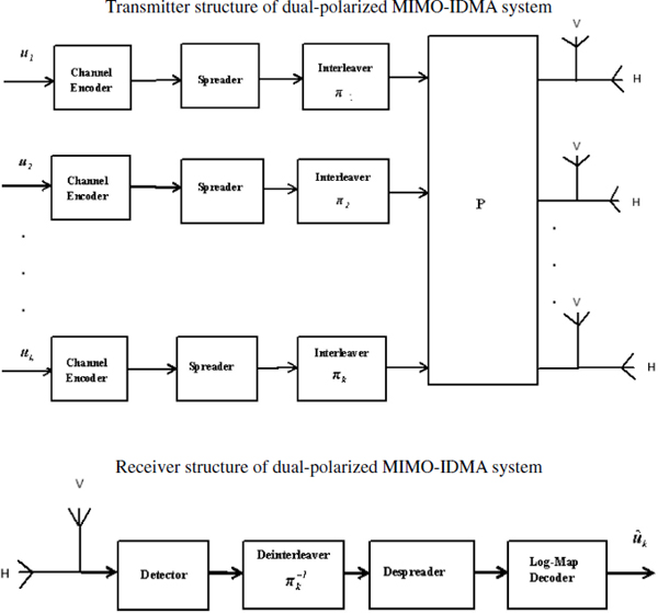
Figure 1 Transceiver structure of single cell multi-user dual-polarized MIMO-IDMA system.
The bit stream is then encoded by the channel encoder.
Let the bits stream transmitted contain m bits after channel encoding and is denoted as bk, the bits transmitted to the k-th user from the base
Where
The input bit stream is then interleaved to overcome the burst errors. The bit stream bkj, j = 1,2,3,…,m is spread with the user-specific orthogonal spreading sequence ck and is expressed as
where Nc is frame length.
The element ck is referred to as the coded bits. Then the ck is permuted by an interleaver πk.
This user-specific spreading matrix is used to obtain the spread sequence of the k-th user having length vector Ncm and is expressed as
The signal of all the users are summed up to obtain xk
Where
The bit streams are transmitted using VBLAST architecture using the dual-polarized antennas.
2.1 Channel Model for Dual-Polarised Antenna Configurations
For the MIMO-IDMA system with dual-polarised antennas, the channel matrix is generally described in terms of the vertical and horizontal polarizations. The transmit and receive relationship between the vertical and horizontal polarizations of the antennas at the BS and MS are described by the channel state information matrix H. This can be modelled with the help of Figure 2 as given by [12, 18]
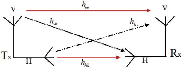
Figure 2 Dual-polarized antenna configuration.
The backdrop of dual-polarised antenna structures suggest the ability to separate the vertical and horizontal polarisation components as described by the cross-polarization discrimination (XPD) factor which is directly related to the random component of the channel. XPD is the main parameter that features the information leakage from one polarisation to another induced by the channel imperfections. Since the electromagnetic waves traverse through the medium, they may undergo depolarisation due to scattering and reflection in the rich fading environment. The XPD for the variable component of the channel can be defined as given by [18]
A symmetric leakage is assumed as suggested in [12]. The parameter β,
Here the following normalizations are assumed.
The XPD for the fixed component matrix of the dual-polarized channel is given by
and the normalizations factor for the dual-polarized antennas is summarized [18] as
In a multi-antenna signalling approach, the elements of spatially separated single polarised channel matrix are correlated when the channels do not exhibit rich scattering and when the antenna spacing is small [18].
The channel matrix for the dual-polarized Nr × Nt, is then expressed as
where
defines the polarization leakage matrix, and Rrx1/2 and Rtx1/2 are the receive and transmit correlation matrices.
Now, without loss in generality, and for specific reference extension to the arrays of several spatially separated dual-polarised antennas can be readily expressed using [18].
In this work, the frequency selective feature of channel matrix has been assumed and it connects k-th MS and BS. The channel model is based on the Standard University Interim (SUI) and Long-Term Evolution (LTE) specifications. The power delay profile for SUI and LTE channel model are summarized in Table 1. The impulse response connecting j-th receive antenna and i-th transmit antenna may be defined as
Where L represents the number of paths between j-th receive antenna and i-th transmit antenna.
The received vector component y at the k-th MS be expressed as,
where H kdp is the dual-polarized Nr × Nt channel matrix and can be written as
Also, nk is the complex Gaussian noise with Nr length vector component and xk is the transmitted Nr × 1 vector component.
Clearly the Equation (19) can be expressed as
where nk′ is the Gaussian complex vector with zero mean and covariance matrix be expressed as
where E{⋅} indicates expected value of argument and σ represents standard deviation.
Table 1 Channel specifications for SUI and LTE channel models
| SUI-1 Channel Model | SUI-5 Channel Model | LTE-Extended Vehicular Channel Model | LTE-Extended Pedestrian Channel Model | |||||
| Path Number (l) | Delay (μs) | Power (dB) p(τl) | Delay (μs) | Power (dB) p(τl) | Delay (ns) | Power (dB) p(τl) | Delay (ns) | Power (dB) p(τl) |
| 1 | 0 | 0 | 0 | 0 | 0 | 0 | 0 | 0 |
| 2 | 0.4 | –15 | 4 | –5 | 30 | –1.5 | 30 | –1 |
| 3 | 0.9 | –20 | 10 | –10 | 150 | 0 | 70 | –2 |
| 4 | 310 | –1.5 | 90 | –3 | ||||
| 5 | 370 | –0.6 | 110 | –8 | ||||
| 6 | 710 | –9.1 | 190 | –8 | ||||
| 7 | 1090 | –7 | 410 | –20.8 | ||||
3 VLAST/MMSE Detection Algorithm
The Minimum Mean Square Estimation (MMSE) algorithm based on the order successive interference cancellation technique (Choi 2006) is considered for detection of the transmitted sequence. The algorithm can be described as follows.
The input-output relationship of MIMO-IDMA system is given by the following equation
Initialize
Recursion
The above MMSE/OSIC detection algorithm is carried out for obtaining
4 Results and Discussion
In this section, the computer simulation and corresponding results of MIMO-IDMA system under SUI and LTE [26–29] channel specifications has been presented. The channel model parameters and simulation parameters are presented in Table 1 and Table 2 respectively.
Table 2 Simulation Parameters
| Parameters | Attributes |
| Modulation technique | BPSK |
| Channel spacing | 20 MHz |
| Sampling frequency | 22.5 MHz |
| Number of dual-polarized antennaat the transmitter | 1 |
| Number of dual-polarized antennaat the mobile station | 1 |
| Channel model | SUI-1, SUI-5, LTE-Extended vehicular and Typical urban |
| Channel coding | Turbo |
| XPD | –3.98 db |
A Doppler shift of 0.5 Hz and 2.5 Hz with antenna correlation of 0.7 and 0.3 for SUI-1 and SUI-5 channel models [26, 28] respectively has been assumed. We presume a Doppler shift of 70 Hz and 300 Hz and mobile moving at velocity of 40 km/hr and 160 km/hr for LTE-typical urban channel model and LTE-extended vehicular respectively [27, 29]. 10,000 channel realizations for each value of SNR has been considered. We realize parallel concatenated convolutional encoder with a rate of 1/2. Further, we consider the value for η to be 0.4.
From the figure, we observe that to acquire a BER of 10-2, the uncoded system requires an SNR of 8 dB. Figure 3 and 4 depict the BER performance of a dual-polarized MIMO-IDMA system for SUI-1 and SUI-5 channel specifications. We observe that the coded dual-polarized MIMO-IDMA system with VBLAST/MMSE algorithm provides a better BER performance with less SNR in comparison with the uncoded dual-polarized MIMO-IDMA
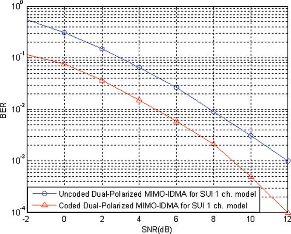
Figure 3 BER vs. SNR performance of coded and uncoded dual-polarized MIMO-IDMA system for SUI-1 channel model.
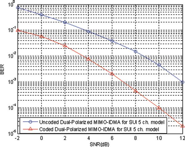
Figure 4 BER vs. SNR performance of coded and uncoded dual-polarized MIMO-IDMA system for SUI-5 channel model.
Figure 5 and 6 indicates the BER performance of dual-Polarized MIMO-IDMA system for LTE pedestrian and vehicular channel model. It is observed that the coded system require to achieve a BER of 10-4 approximately 10 dB From the Figure 7, it is observed that to achieve a BER of 10-4, the considered system with an uni-Polarized antenna require 3.5 dB SNR than the dual-Polarized antenna requires 10 dB under SUI-5 and LTE channel
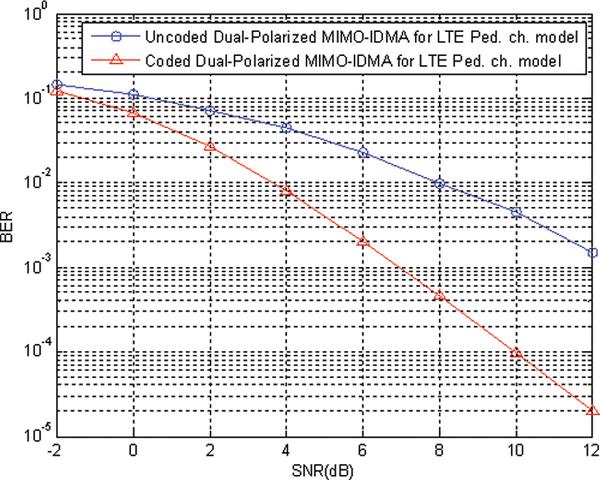
Figure 5 BER vs. SNR performance of coded and uncoded dual-polarized MIMO-IDMA system for LTE Ped. channel model.
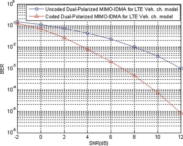
Figure 6 BER vs. SNR performance of coded and uncoded dual-polarized MIMO-IDMA system for LTE Veh. channel model.
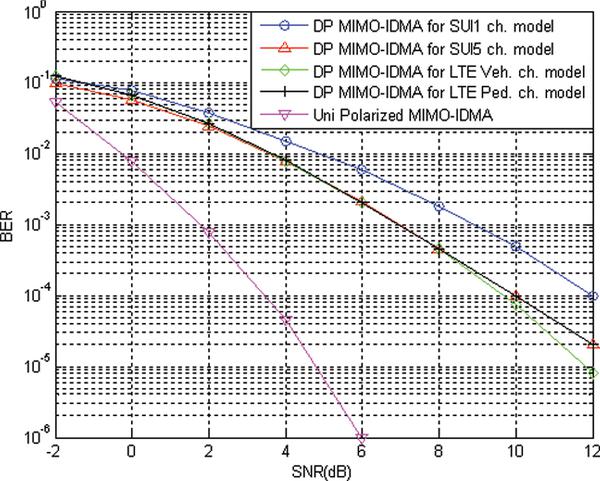
Figure 7 Comparison of uni-polarized and dual-polarized MIMO-IDMA system.
Figure 8 illustrates the performance of the number of iterations with different SNR, it is inferred that our considered dual-polarized MIMO-IDMA system with turbo code achieves BER of 10-4 after the fifth iteration of 7 dB for SUI and LTE channel models.
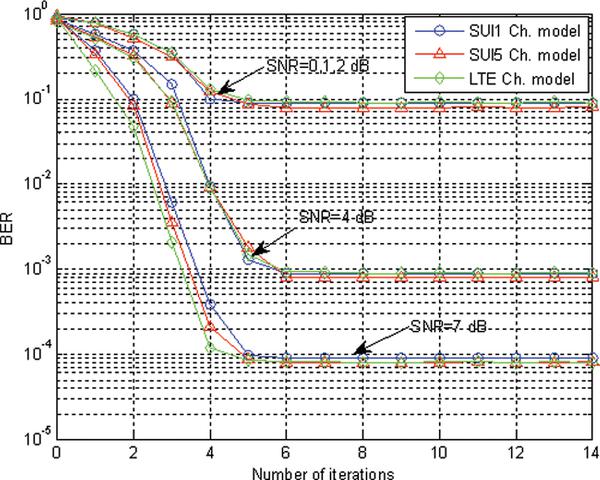
Figure 8 BER vs. No. of Iterations dual-polarized MIMO-IDMA system with various channel models.
5 Conclusion
In this paper, we investigated the BER performance of a turbo coded dual-polarized MIMO-IDMA system for frequency-selective channels based on SUI and LTE channel specifications in the context of DL communication. The ability of path-dependent Doppler and angle spread with rich scattering that degrades the BER performance of the system has been considered and solutions are provided to mitigate the effects of MSI both at the transmitter and receiver. The results show better performance when the system is equipped with dual-Polarized MIMO-IDMA employing turbo style of iterative decoding algorithm. The overall systems provides better BER performance with less SNR irrespective of the channel conditions while offering higher data rate with reduced size of MSs.
References
[1] Oestges, C., Erceg, V., and Paulraj, A. J. (2004). Propagation modeling of MIMO multipolarized fixed wireless channels. IEEE Transaction on Vehicular Technology (53), 644–654.
[2] Foschini, G., and Gans, M. (1998). On limits of wireless communications in a fading environment when using multiple antennas. Wireless Personal Communication (6), 311–335.
[3] Ping, L., Liu, L., Wu, K., et al. (2006). Interleave-division multiple access. IEEE Transaction on Wireless Communication (5), 938–947.
[4] Ping, L. (2005). Interleave-division multiple access and chip-by-chip iterative multi-user detection. IEEE Communication Magazine
[5] Kusume, K., and Bauch, G. (2005). CDMA and IDMA: Iterative multiuser detections for near-far asynchronous communications, in Proceedings of IEEE PIMRC, Berlin, Germany, 426–431.
[6] Partibane, B., Nagarajan, V., Vishvaksenan, K. S., et al. (2015). Performance of Multi-User Transmitter Pre-Processing Assisted Multi-Cell IDMA System for Downlink Transmission. Fluctuation and Noise Letters (14), 1550030-16, doi: 10.1142/S0219477515500303
[7] Kusume, K., Dietl, G., Utschick, W., et al. (2007). Performance of interleave division multiple access based on minimum mean square error detection, in Proceeding of IEEE International Conference on Communication, Glasgow, UK, 2961–2966.
[8] Cristea, B., Roviras, D., and Escrig, B. (2009). Turbo receivers for interleave division Multiple access systems. IEEE Transaction on Communication (57), 2090–2097.
[9] Kusume, K., Bauch, G., and Utschick, W. (2009). IDMA vs. CDMA: Detectors, performance and complexity, in Proceedings of IEEE GLOBECOM, Honolulu, HI,USA.
[10] Novak, C., Hlawatsch, F., and Matz, G. (2007). MIMO-IDMA: Uplink multiuser MIMO communications using interleave-division multiple access and low-complexity iterative receivers, in Proceedings of IEEE ICASSP, Honolulu, HI, USA, 225–228.
[11] Hao, D., and Hoeher, P. A. (2008). Helical interleaver set design for interleave division multiplexing and related techniques. IEEE Communication Letters (12), 843–845.
[12] Nabar, R.U., B’lcskei, H., Erceg, V., et al. (2002). Performance of multi antenna signalling techniques in the presence of polarization diversity. IEEE Transaction on Signal Processing (50), 2553–2562.
[13] Zhou, X., Shi, Z., and Reed, M. C. (2007). Iterative channel estimation for IDMA systems in time-varying channels. In Proceedings of IEEE GLOBECOM, Washington, DC, USA, 4020–4024.
[14] Hoeher, P. A., Schoeneich, H., and Fricke, C. (2008). Multi-layer interleave-division multiple access: Theory and practice. European Transaction on Telecommunication (19), 523–536.
[15] Mahafeno, I., Langlais, C., and Jego, C. (2006). OFDM-IDMA versus IDMA with ISI cancellation for quasi-static Rayleigh fading multipath channels, in Proceedings of 4th International Symposium on Turbo Codes Related Topics, Munich, Germany, 3–7.
[16] Ping, L., Guo, Q., and Tong, J. (2007). The OFDM-IDMA approach to wireless communication systems. IEEE Wireless Communication (14), 18–24.
[17] Novak, C., Matz, G., and Hlawatsch (2009). Factor graph based design of an OFDM-IDMA receiver performing joint data detection, channel estimation, and channel length selection, in Proceedings of IEEE ICASSP, Taipei (Taiwan), 2561–2564.
[18] Aamir Habib (2012). Receive antenna selection in diversely polarized MIMO transmissions with convex optimization. Elsevier Journal on Physical Communications (5), 328–337.
[19] Loeliger, H. A., Dauwels, J., Hu, J., et al. (2007). The factor graph approach to model-based signal processing, in Proceedings IEEE 2007, Vol. 95, 1295–1322.
[20] Boutros, J., and Caire, G. (2002). Iterative multiuser joint decoding: Unified framework and asymptotic analysis. IEEE Transaction on Information Theory (48), 1772–1793.
[21] Worthen, A. P., and Stark, W. E. (2001). Unified design of iterative receivers using factor graphs. IEEE Transaction on Information Theory (47), 843–849.
[22] Valenti, M. C., and Woerner, B. D. (2001). Iterative channel estimation and decoding of pilot symbol assisted turbo codes over flat-fading channels. IEEE Journal on Selected Areas Communication (19),
[23] Huaning, N., Manyuan, S., Ritcey, J., et al. (2005). A factor graph approach to iterative channel estimation and LDPC decoding over fading channels. IEEE Transaction on Wireless Communication (4), 1345–1350.
[24] Liu, Y., BruneL, L., and Boutros, J. J. (2008). Belief propagation with Gaussian approximation for joint channel estimation and decoding, in Proceedings of IEEE PIMRC, Cannes, France, 1–5.
[25] Zhao, M., Shi, Z., and Reed, M. C. (2008). Iterative turbo channel estimation for OFDM system over rapid dispersive fading channel. IEEE Transaction on Wireless Communication (7), 3174–3184.
[26] Kermoal, J. P., Schumacher, L., K. Pedersen, K. L., et al. (2002). A stochastic MIMO radio channel model with experimental vali-
[27] 3GPPP(TR 30.803) (2007). Evolved universal terrestrial radio access (E-UTRA) user equipment (UE) radio transmission and reception (Release8). Technical specification, 2007, Sophia Antipolis, France.
[28] IEEE 802.16a-03/01. Channel Models for Fixed Wireless Applications, 2003-06-27.
[29] 3GPP TR25.996 V6.1.0. Spatial Channel Model for Multiple Input Multiple Output (MIMO) Simulation (Rel.6), 2003-09.
[30] Kalidoss, R., Vijayarangan, V, and Sukanesh, R. (2006). “Low Crest Mapping for PAPR reduction in OFD M system”, IET International Conference on Wireless, Mobile and Multimedia Networks,
[31] Kalidoss, R., Bhagyaveni, M. A., and Vishvaksenan, K. S. (2014). A location based duplex scheme for cost effective rural broadband connectivity using IEEE 802.22 cognitive radio based wireless regional area networks. Fluctuation and Noise Letters (13).
[32] Karthipan, R., Vishvaksenan, K. S., Kalidoss, R., and Sureshbabu, R. (2016). Uplink capacity enhancement in IEEE 802.22 using modified duplex approach. Wireless Personal Communication (86),
[33] Vishvaksenan, K. S., Mithra, K., Kalidoss, R., and Karthipan, R. (2016). Experimental study on Elliot wave theory for Handoff Prediction. Fluctuation and Noise Letters (15), 1–11.
[34] Vishvaksenan, K. S., Kalaiarasan, R., Kalidoss, R., and Karthipan, R. (2017). “Real time experimental study and analysis of Elliott wave theory in signal strength prediction,” in Proceedings of National Academy of Sciences, Springer, 2017. (Article in Press).
[35] Saravanan, M., Kalidoss, R., Partibane, B., and Karthipan, R. (2017). Mitigation of mutual exclusion problem in 5G new radio standards by token and non token based algorithms. Cluster Computing, 2017.
Biographies

B. Partibanereceived his B.E. degree in ECE from Madras University, Chennai, in 1999, and the M.Tech degree in ECE from Pondicherry University, Pondicherry, in 2003. Further, he obtained doctoral degree from Anna University, Chennai in 2017. He currently holds an academic post as Associate Professor in the department of ECE, SSN Institutions. His research interests include Wireless Communication and Networks, Antenna Engineering and Security in Ad hoc and Sensor Network.

R. Kalidoss completed bachelor degree (B.E., 2004) in Electronics and Communication Engineering from Madurai Kamaraj University and master degree (M.E., 2006) in Communication Systems from Anna University, Chennai. Further, he obtained doctoral degree (Ph.D., 2015) from Anna University, Chennai. He currently holds an academic post as Associate Professor in the department of ECE, Sri Siva Subramaniya Nadar College of Engineering, Chennai. His current research interests include Adaptive Channel Modeling in Cognitive Radio, Advanced Spectrum Utilization and Cognitive Radio architecture. He has published/presented over 20 research articles in refereed International/National Journals/Conferences.

R. Karthipan received his B.E. degree in Electrical and Electronics Enginee-
Journal of Cyber Security, Vol. 6_4, 379–396.
doi: 10.13052/jcsm2245-1439.641
This is an Open Access publication. © 2017 the Author(s). All rights reserved.