Information Hiding Based on Histogram and Pixel Pattern
Ari Moesriami Barmawi* and Deden Pradeka
Informatics Graduate Program, School of Computing, Telkom University, Indonesia
E-mail: mbarmawi@melsa.net.id; deden.pradeka@gmail.com
∗Corresponding Author
Received 29 August 2017; Accepted 24 December 2017;
Publication 1 February 2018
Abstract
Recently, information exchange using internet is increasing, such that information security is necessary for securing confidential information because it is possible to eavesdrop the information. There are several methods for securing the exchanged information such as was proposed by Rejani et al. Rejani’s method can be noiseless in low capacity but noisy in high capacity. In the case of high capacity, it will raise suspicion. This research proposed a method based on histogram and pixel pattern for keeping the stego image noiseless while still keeping the capacity high. Secret information can be embedded into the cover by evaluating the histogram and map the characters used in the secret message to the consecutive intensity in the cover image histogram. The map of the characters is sent to the recipient securely. Using the proposed method there is no pixel value changes during the embedding process. Based on the result of the experiments, it is shown that in noiseless condition, the proposed method has higher embedding capacity than Rejani’s especially when using cover image with sizes larger than 128 × 128. Thus, in noiseless condition the embedding capacity using the proposed method is higher than Rejani’s method in noiseless condition.
Keywords
- Steganography
- Histogram
- Mod bit algorithm
- Pixel value
1 Introduction
Nowadays, internet is used for data communications between two or more parties, such that securing and protecting data are necessary. There are two methods for securing and protecting data: cryptography and steganography [1]. Cryptography is a technique for protecting the secret messages by changing the messages into a code, such that unauthorized party cannot understand it. Steganography is the art of protecting secret messages by embedding the message into a cover. The cover can be innocent digital media file such as images, videos, audios, texts, voices, smart phones, cloud storage services and the Skype video traffic. The main difference between cryptography and steganography is that using cryptography [1, 2], the message is sent after it was modified into code, such that it will raise suspicion. Meanwhile, using steganography [4, 5] it will not raise suspicion since the message is embedded into a cover where the changes of the cover cannot be directly perceived by human. Recently, steganography is combined with cryptography for increasing the security of information [2]. In some applications, where the content’s owner did not trust the embedded information, then the message was encrypted by the owner before it was embedded into the cover.
This paper discussed about steganography which is used along with cryptography which is applied to an image as the cover. There are several steganography methods which has been proposed such as proposed by
For overcoming the problem of Rejani’s method [3], a histogram and pixel pattern based steganography is proposed. The basic idea of the proposed method was embedding the code of the character without generating noise in the cover. This idea was implemented by observing the range of pixel value which matched with the character code. Furthermore, the character code of each unique character in the message should be compared with the function of pixel value. If they were equal, then the pixel position was sent to the receiver after randomized. Otherwise, another pixel would be observed and checked whether the function of the pixel value is equal. This process was conducted for all pixels in the image until the function of the designated pixel was found. Thus, using the proposed method no pixel value would be modified or changed, such that there was no noise in the cover
Based on the experiment result, it was shown that there was no noise in the cover image if messages with less than or equal to 95 unique characters were used, while using Rejani’s method the noise would be generated if the embedded message consisted of more than 29 characters. This method can be implemented in a grey scale cover which is compressed using lossless compression.
2 Information Hiding Based on Pixel Pattern
Rejani proposed an information hiding method which is not only hiding message behind the image, but also strengthen the security. A message is embedded into an image by finding the value of the pixel mod bit that is equal to character code, and further use the pixel as the character representation. The pixel position that represents each character is encrypted and recorded in the image metadata. The cover image including its metadata is sent to the receiver, while the key used to encrypt data should be agreed upon in advance. The overview of the embedding process is shown
In hiding (embedding) process mod bit function is used. The basic idea of this method is finding a value by calculating the pixel value mod N, where N is the number of unique character used in the message. Suppose the pixel value is p and p consists of m numbers p1,p2,…,pm, then calculate di as follows:
Furthermore, calculating the sum of di mod N:
Where mp is the result of mod bit function which further will be evaluated whether it is equal to the character’s code.
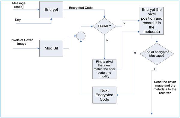
Figure 1 Rejani’s embedding process.
For embedding the information, three input is needed which are image cover, message and key for the encryption process. The detail of the process is shown in Figure 1 and it can be described as follow:
- Encrypt the message using RSA [13] or DES [14].
- Change the unique characters in the encrypted message into specific code.
- Get a pixel value and calculate the mod bit function.
- If the mod bit result equal to the character code, then encrypt the pixel position and record it in the image meta data.
- Otherwise, observe another pixel in the image and repeat step 4.
- If there is no mod bit of the pixel value which is equal to the character code, then find a pixel throughout the image whose mod bit value is the nearest one to the character code and modify the pixel value such that it is equal to the character code.
- Repeat step 2–5 until the last character of the message.
For extracting the message, the receiver should get the key and decrypt the encrypted position of the pixel. Furthermore, find the pixel value from the intended position, and calculate the mod bit of the pixel value.
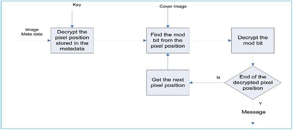
Figure 2 Rejani’s extracting process.
Finally, decrypt the mod bit value using the key that has been agreed upon in advance. The overview of the extraction process is shown in Figure 2.
3 The Proposed Method
For overcoming the problem of Rejani’s method where there are still possibilities that the pixel value is modified, information hiding based on histogram and pixel pattern was proposed. For embedding the message, the sender chose a cover from the cloud, and embedded a message into the image based on histogram [8] and pixel position. In this case a seed was agreed upon in advance by both the sender and the receiver. Instead of using encryption for encrypting the message and the pixel position, this proposed method used number theory concept for strengthening the method.
3.1 Embedding Process
The embedding process consisted of three processes i.e. randomizing unique character order, selecting intensity, and message camouflaging. The goal of unique character order randomizing process was to obtain random order of unique characters instead of only ordered based on alphabet order. The output of this process was random ordered unique character which was the input of selecting intensity process. The goal of selecting intensity process was obtaining intensity range that can be used for representing the unique characters. Further, the intensity range would be used as an input for camouflaging message process. In this process the message camouflaging would be based on the intensity range that can be used for representing the message. The overview of embedding process was shown
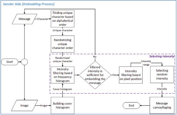
Figure 3 Embedding process.
3.1.1 Randomizing unique character order
Randomizing unique character order process is a process that randomized the order of unique characters used in the message. The function of randomizing unique character order process was to secure the characters used in the secret message, instead of using encryption since encryption needs more resources. There were two sub-processes for randomizing character order i.e. finding unique character of the message, and randomizing unique character. Finding unique character used in a message was done by segmenting the message into characters and classified unique character used in the message. For randomizing the unique character order, a method as shown in Figure 4 was used.
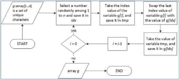
Figure 4 Method for randomizing unique character order.
3.1.2 Selecting intensity
Selecting and randomizing intensity to represent the unique character were conducted for camouflaging the message. There were three steps in choosing intensity process, i.e. intensity filtering based on intensity frequency, intensity filtering based on pixel position and selecting random intensity [9] for representing of unique character.
Selecting intensity process was intensity filtering based on the frequency of intensity. The implementation of this process was by comparing the frequency of unique character and the frequency of specific intensity. If the frequency of specific intensity (fi) was larger than or equal to the frequency of unique character (gj), then the related intensity can be used to represent the unique character, or in other words the intensity was chosen as the valid intensity to represent a specific unique character, and the status st was set to 1. Otherwise, the specific intensity could not represent the specific character, and st was set to 0 (see Equation (3)).
Suppose the number of unique character is n such that 0 < j ≤ n, and the number of intensity code is 256 such that 0 ≤ i ≤ 255. If all stj (for j = 1,2,…,n) was 1, such that gj (for j = 1,2,…,n) was represented by fi (for i = s,s + 1,…,s + n- 1; where s was the starting index of pixel whose intensity could be used to represent character g1), then the fulfillment indicator tfi = 1 [10] (see Equation (4)).
Suppose Figure 5(A) illustrates the cover histogram, and Figure 5(B) is the message histogram of the unique character. Furthermore, the frequency between cover histogram and message histogram were compared, starting from the smallest intensity of the cover histogram.
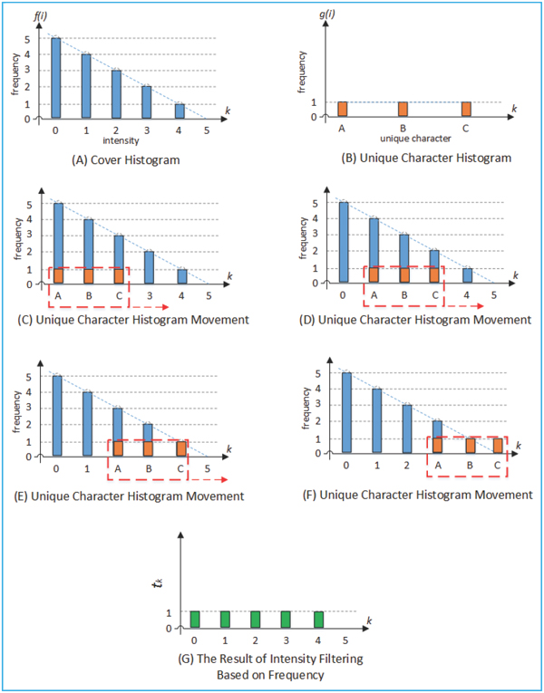
Figure 5 Intensity filtering based on frequency. (A) Cover histogram, (B) Unique character histogram, (C)–(F) Unique character movement, and (G) The result of filtering or
The capacity fulfillment of cover histogram is shown in Figure 5(C). This can be illustrated in Figure 5(C) that the frequency of the intensity 0, 1, and 2 of the cover is greater than the intensity frequency of A, B, and C in the message. In this condition the value of capacity fulfil-ness will be 1. The result of filtering process is shown in Figure 5(G) while Figure 5(D), (E), and (F) shows the step by step process.
The second step of selecting intensity process was intensity filtering based on pixel position. For minimizing the number of bit represented the pixel position, then minimizing the position distance between two pixels represented the unique characters was proposed. This process filtered the intensity based on the distance of position between two pixels whose intensity difference is one. The maximum distance should be less than 16 such that the representation of the distance will not exceed 4 bits. If the distance is greater than 16, then the process was repeated until a set of pixels representing unique characters was found. The position distance between 2 pixels in the set that represented two unique characters should be less than 16. Suppose the cover capacity fulfil-ness is as shown in Figure 6(A), the message histogram as shown in Figure 6(B) and the cover pixel positions as shown in Figure 6(C). The intensity difference between two intensities represented the unique characters should be 1. There are two processes that should be conducted for obtaining the distance between two pixels used to represent the unique characters. They are finding and storing the positions of pixels in the range of filtered intensity and calculating the distance between two pixels whose intensity difference is one. Suppose the intensity representing 0, 1, and 2 respectively as shown in Figure 6(D). Then, the position of pixels with intensity 0 should be searched and its position should br stored in the storage. This process is executed for intensities 1 and 2 as well. The position distance is calculated by calculating the distance between row and column of the intended pixels. If RAi, and RAi-1 is the row number of character B and A respectively, while RBi, and RBi-1 is the row number of character C and B respectively, then the distance between the row number of A and B is Row A = RAi – RAi-1, and the distance between the column number is Column A = CAi – CAi-1. This process was also executed for calculating the position between character B and C. Finally, after the distances were collected, the sender would select pairs of pixels whose intensity difference between pixels in one pair is one and with the distance of position less than 16.
Assume that for representing a message consisted of n characters (c1, c2, c3,…, cn), n consecutive intensities (x1, x2, x3,…, xn, where xi+1 – xi =1) were necessary. Each intensity represent one character such that map (ci) = xi.
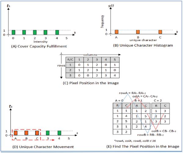
Figure 6 Intensity filtering based on the pixel position. (A) Capacity fulfillment, (B) Unique character histogram, (C) Pixel position, (D) Unique character movement, and (E) Find the pixel position.
In this case, the distance of position between xi and xi+1 should be less than 16. Suppose the number of unique character used in a message is n =5, then the cover fulfil-ness is as shown in Figure 7(A) and the result of filtering based on pixel position is as shown in Figure 7(B). Then, it is shown that pixel with intensity of x1, x2, x3, x4, x5 could be used for representing unique character c1, c2, c3, c4, c5 which is M, A, K, N, and E respectively. Furthermore, map(ci) for i = 1, 2, 3, 4, 5 were x1, x2, x3, x4, x5 respectively. Thus, the distance of position between pixel(xi+1) and pixel(xi) (where pixel(xi) is a pixel whose intensity is xi) should be less than 16. If this requirement can not be fulfilled in the range of xi to xnthen xi should be shifted to xi+1 and find the distances between pixel(xi+1) and pixel(xi). In the case of Figure 8, the requirement can be fulfilled in the intensity range of 16–31. While it can not be fulfilled in the intensity range of 200 to 203 since there were some pairs of pixels whose intensity difference was less than one and the difference of positions
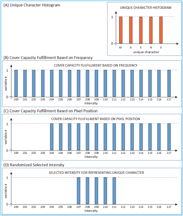
Figure 7 The result of intensity filtering based on pixel position. (A) Unique character. (B) Embedding capacity fulfillment based on frequency. (C) Cover capacity fulfillment based on position. The pixel with intensity of 207, 208, 209, 210, and 211 could be used for representing the unique character, and (D) Selected intensity for representing unique character.
was greater than 16. Finally, the result of intensity filtering based on pixel position is shown in Figure 7(C), where pixel intensities of 204 to 217 could be used for representing unique characters. Since intensities 204–217 can be used to represent the unique characters, then for mapping characters M, A, K, N and E any five consecutive pixels intensity in this range could be used. For example pixels with intensities 207, 208, 209, 210 and 211 were selected at random for representing unique character M, A, K, N, and E respectively.
Suppose the unique character for secret message ‘KEAMANAN’ is M, A, K, N and E and the selected intensities represented the unique characters are as shown in Table 1.
Table 1 Randomized selected intensity for representing M, A, K, N, E
| Unique Character: | M | A | K | N | E |
| Intensity: | 207 | 208 | 209 | 210 | 211 |
Then, the positions of pixels (rows and columns) representing the pixels with intensities of 26, 27, 28, 29, and 30 (in the cover image) is shown in Table 2.
Table 2 Rows and columns of pixel used
| Intensity: | 207 | 208 | 209 | 210 | 211 |
| Rows: | 3 | 4 | 6 | 6 | 7 |
| Columns: | 407 | 407 | 409 | 410 | 411 |
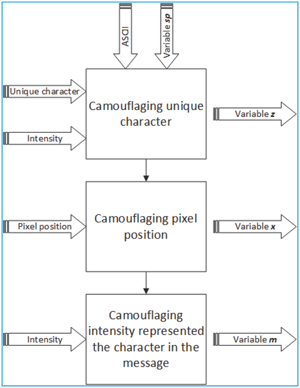
Figure 8 Message camouflaging process.
3.1.3 Message camouflaging
The objective of message camouflaging process was to camouflage a message using an image. There were three steps in message camouflaging process i.e. camouflaging unique character, camouflaging pixel position, and camouflaging character position in the message. The message encoding process was described in Figure 8.
3.1.4 Camouflaging the unique character
The objective of camouflaging unique character was to change a unique character into a number. Suppose the secret message was ‘KEAMANAN’, and the unique characters based on the order in the message were K, E, A, M, and N. After randomizing the order, the randomized order of unique characters were M, A, K, N, and E. The selected intensities for representing unique characters were 207, 208, 209, 210 and 211. Furthermore, the camouflaging unique character process consisted of the following steps:
- The first step was to change the unique character into a number based on ASCII code, and the result was M=77, A=65, K=75, N=78, and E=69. These numbers were stored as variable a.
- The second step was to find the modulus number sp, that was the prime number used in Diffie-Hellman method [12]. Suppose variable sp was 241. There were two parties Alice and Bob that would like to communicate with each other. Alice and Bob published a number p = 449 as the modulo number of Diffie-Hellman equation, and number q which were relatively prime with p (in this case q = 113). Then, the sender, Alice chose her secret number 1a = 3 and the receiver Bob also chose his secret number 1b = 5. Furthermore, Bob computed B (B ≡ qlb mod p), and the result was B = 34. Alice sent A (A ≡ qla mod p) to Bob, and Bob also sent B to Alice. Finally, Alice calculated their common secret modulo number sp ≡ Bla mod p, where the result was sp = 241. Bob also calculated their common secret using sp ≡ Alb mod p which was equal to 241. This common secret would be used as both parties’ common modulo number.
- Suppose the intensity of a pixel representing the unique character was d, then the modular inverse of intensity d which was d-1 modulo sp should be calculated. If intensity d used for representing the unique characters were 207, 208, 209, 210, and 211, then the result of d-1 mod sp [11] is as shown in Table 3.
Table 3 Modular inverse of d mod sp
| d mod sp: | 207 mod 241 | 208 mod 241 | 209 mod 241 | 210 mod 241 | 211 mod 241 |
| d-1: | 163 | 73 | 128 | 171 | 8 |
- Furthermore, the sender calculated z using Equation (6) [11]. The result of Equation (6) for d as shown in Table 3 is shown in Table 4.
Table 4 The result of multiplicative inverse
| a.d-1mod sp: | 77.163 mod 241 | 65.73 mod 241 | 75.128 mod 241 | 78.171 mod 241 | 69.8 mod 241 |
| z: | 19 | 166 | 201 | 83 | 70 |
3.1.5 Camouflaging the pixel position
The purpose of camouflaging pixel position was normalizing the pixel position to 16. Suppose the intensity used to represent the unique character (‘MAKNE’) was 207, 208, 209, 210, 211, and the position of pixels representing the unique character were (3,407), (4,407), (6,409), (6,410), and (7,411) respectively. The process for normalizing the pixel position was conducted as follows:
The first step was to find the position of the pixel representing intensity of 207 which had the smallest index (address) of row and column. Suppose the smallest index of row kr was 3, and the smallest index of columns kc was 407. The sender and receiver should agree in advance on variables
The second step was camouflaging each pixel position using Equation (7) for rows, and Equation (8) for columns.
where ri was a rows value and ci was a columns value from pixel position, xri is a variable with index i to save normalized rows ri, and xci is a variable with index i to save normalized columns ci. The result of camouflaging pixel position is shown in Table 5.
Table 5 The result of camouflaged position
| xr: | 0 | 1 | 2 | 0 | 1 |
| xc: | 0 | 0 | 2 | 1 | 1 |
Finally, all xri and xci should be concatenated together to form an array of numbers. In the case of Table 5, the array was 0, 1, 2, 0, 1, 2, 0, 0, 2, 1, 1.
3.1.6 Camouflaging intensity representing the character
The objective of camouflaging intensity that represented the character in the message was to change intensities that represented a character in the message into a code. Suppose the unique characters of the secret message ‘KEAMANAN’ were M, A, K, N, E which were represented by pixels with intensities 207, 208, 209, 210, 211 respectively. Camouflaging intensity that represented the character in the message had the following steps:
The first step was to change the intensity represented each unique character into a code w using Equation (9).
Where variable d was the intensity and n was number of unique character in the message and the result is shown in Table 6.
Table 6 Result of camouflaging intensity process
| Unique Character: | M | A | K | N | E |
| d mod n: | 207 mod 5 | 208 mod 5 | 209 mod 5 | 210 mod 5 | 211 mod 5 |
| w: | 2 | 3 | 4 | 0 | 1 |
The second step was to change each character of the message into a code. Furthermore, the variable m should be generated from the code of unique character w (see Table 6). Suppose the first character in the secret message ‘KEAMANAN’ was ‘K’, and it was represented by intensity of 4. Thus, the value of array m for message ‘KEAMANAN’ was 4, 1, 3, 2, 3, 0, 3, and 0, as shown in Figure 9.
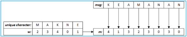
Figure 9 The result of camouflaging character position in the message.
After conducting all process for embedding message, then the sender store the sender randomized x, z and m in the metadata of the image. In this case, sp, kr, kc and the method for randomizing x, z and m will be agreed upon by both parties.
3.2 Message Extraction Process
After receiving the cover image, x, z and m, the receiver can extract the message. The decoding process is shown in Figure 10. There were three processes for extracting the message, (a) extracting the position of the pixel represented the unique character for obtaining its intensity, (b) extracting the ASCII code of the unique character that would be used for obtaining the unique character and finally (c) extracting the message.
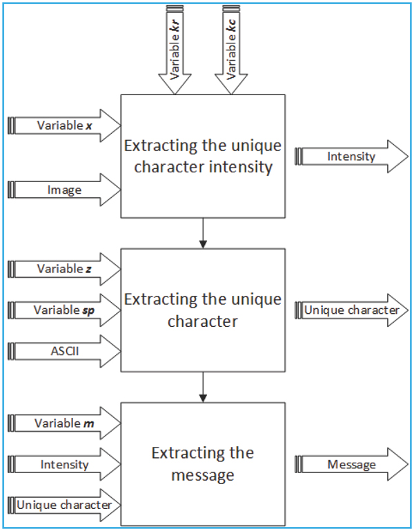
Figure 10 Decoding process.
3.2.1 Extracting unique character intensity
The objective of extracting unique character intensity process was to obtain intensity used in the cover. The input of this process was variable x (code number of pixel position), cover image, variables kr and kc (see camouflaging pixel position). Suppose the cover was Lena (with image size of 512 × 512) as shown in Figure 12, x = 0, 1, 2, 0, 1, 0, 0, 2, 1, 1, kr is 3 and, kc is 407, then xr = 0, 1, 2, 0, 1 and xc = 0, 0, 2, 1, 1. The procedure for extracting the intensity of unique character is described as follows:
The first step was obtaining the row index and the column index of the pixel whose intensity represented the unique character using Equations (7) and (8). The result is shown in Table 7 where rows is the index of row and columns is the index of column.
Table 7 The result of extracting pixel position process
| 3 | 4 | 6 | 6 | 7 | |
| 407 | 407 | 409 | 410 | 411 |
The second step was to find the intensity using the pixel position on the cover image, as shown in Figure 11, where it was obtained that the intensity used for representing the unique characters were 207, 208, 209, 210 and 211.
3.2.2 Extracting the unique character
The process of extracting the unique character needed z as the input, y (intensity obtained from the process for extracting the intensity), and sp (secret modulo number). Suppose variable z were 19, 166, 201, 83, 70, y were 207, 208, 209, 210, 211, and sp = 241. Then, for extracting the unique character, the following procedure should be conducted.
At first, extract the ASCII code of unique characters using z and
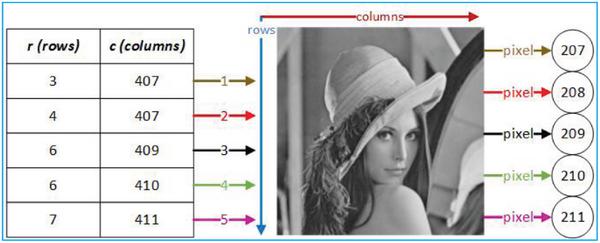
Figure 11 Finding Intensity process.
Table 8 Extracted ASCII Code of the unique character
| z.y mod sp: | 19.207 mod 241 | 166.208 mod 241 | 201.209 mod 241 | 83.210 mod 241 | 70.211 mod 241 |
| a: | 77 | 65 | 75 | 78 | 69 |
Table 9 The extracted unique character
| a: | 77 | 65 | 75 | 78 | 69 |
| cal: | M | A | K | N | E |
Furthermore, the ASCII code should be converted into the unique character, and the result is shown in Table 9, where cal was the unique character.
3.2.3 Extracting the message
For obtaining the message, m and cal were necessary. In this case, m were 4, 1, 3, 2, 3, 0, 3, 0, unique character cal were M, A, K, N, E, intensity y were 207, 208, 209, 210 and 211, and the number of unique character n was 5.
For changing the numbers in m into the code represented the unique character w, the second step was to change the intensity y into a code using Equation (13), and the result is shown in Table 10.
The final step, variable m should be changed into a character based on the extracted unique character code. Suppose the unique characters were M, A, K, N, E, and their codes for representing of unique character were 2, 3, 4, 0, and 1 respectively, then the message can be extracted as “KEAMANAN” as shown in Figure 12.
Table 10 The extracted unique character code
| d mod n: | 207 mod 5 | 208 mod 5 | 209 mod 5 | 210 mod 5 | 211 mod 5 |
| w: | 2 | 3 | 4 | 0 | 1 |
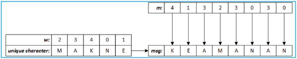
Figure 12 Message extraction.
4 Experiment and Discussion
This section discussed about capacity evaluation in term of embedding capacity without pixel changes. This experiment used 128 × 128, 256 × 256 and 512 × 512 cover image, with 30 type of cover image. Besides, analysis based on steganalysis also observed in this section.
4.1 Capacity Evaluation
For evaluating the effectiveness of the proposed method, comparison of embedding capacity between the proposed and Rejani’s method should be conducted. For evaluating the embedding capacity, two experiment’s scenarios had been conducted. The first one was embedding the unique characters represented by ASCII symbol into image covers using Rejani’s method and the second one was using the proposed method. This process was conducted using 30 types of cover image with three sizes 512 × 512, 256 × 256, and 128 × 128 for each types of cover image. In this case, the definition of embedding capacity was the capacity of a cover image to be embedded by text (array of characters) without changing the pixel intensity. In this case, 131 characters of message length with 95 unique characters was used. The embedding capacity as the result of the experiments was shown in Figure 13.
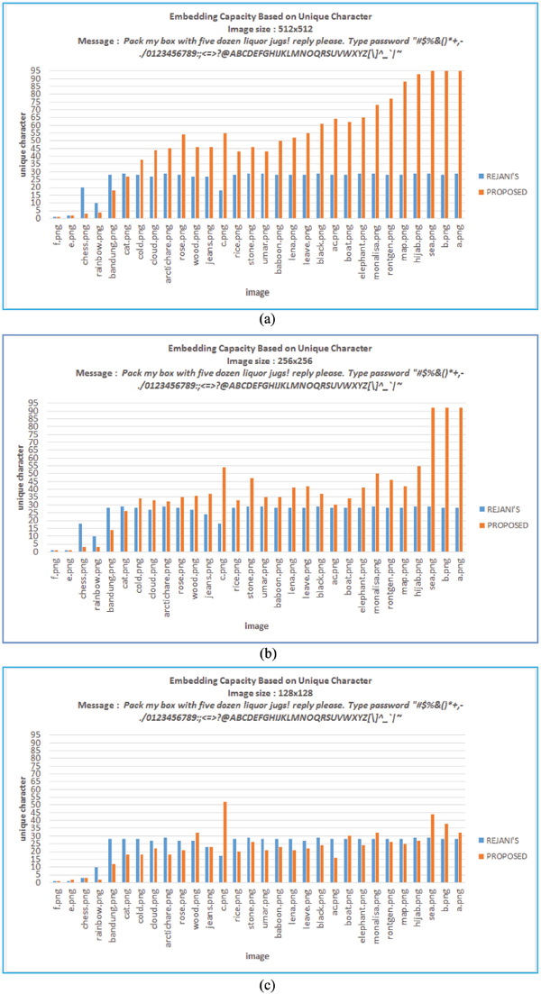
Figure 13 Embedding capacity using Rejani’s and proposed method. (a) Cover image size of 512 × 512. (b) Cover image size of 256 × 256. (c) Cover image size of 128 × 128.
Based on Figure 13, it is shown that the highest embedding capacity of the proposed method was obtained when image covers of 512 × 512 and 256 × 256 were used (see Figure 13(a), since there were only four cases where the embedding capacity of the proposed method was less than the embedding capacity of Rejani’s. However, if a 128 × 128 cover image was used, then there were more than four cases (19 cases) where the embedding capacity of the proposed method was less than Rejani’s were occurred. This condition was occurred because the proposed method required high frequency for each intensity as well as wide range of intensity to represent unique character code, while in Rejani’s method neither high frequency of each intensity (which was used as the code of unique character) nor wide range of intensity was necessary since it was possible for changing the pixel value based on the value such that it would be equal to the code of unique character. The larger the size of cover image, the larger the frequency of each intensity, then this would increase the embedding capacity of the proposed method. Furthermore, observation on cases where the embedding capacity of the proposed method was less than Rejani’s one was conducted.
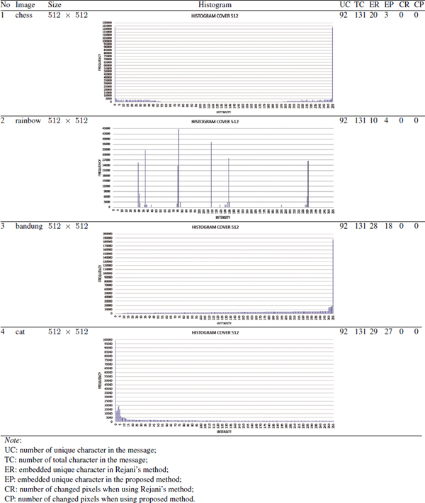
Since the high embedding capacity using the proposed method was occurred when hijab.png, sea.png, b.png and a.png were used, then the observation would focus on those cover image. Table 11 shows the characteristic of hijab.png, sea.png, b.png, and a.png. Based on Table 11, it can be concluded that the frequency of those four image intensity were high and/or the range of intensity was wide. As the impact of this condition, the embedding capacity of the proposed method was completely higher than Rejani’s without any pixel changes. On the contrary, the embedding capacity of chess.png, rainbow, bandung.png, and cat.png was low and/or the range of intensity was narrow as shown in Table 12. As the impact of this condition, the embedding capacity of the proposed method was less than Rejani’s, since the frequency of intensity was low. In the proposed method, Low frequency of intensity causes the insufficient number of pixel represented the unique character, while in Rejani’s method frequency of intensity was not influenced the representation of unit character.
Table 11 Embedding capacity 512×512 cover images whose the embedding capacity using the proposed method was greater than the embedding capacity using Rejani’s
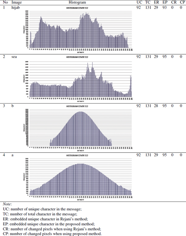
Table 12 Characteristic of 512 × 512 cover images whose the embedding capacity using the proposed method was less than the embedding capacity using Rejani’s
4.2 Steganalysis
Since there is no pixel intensity changes in the cover image, the steganalysis is not conducted based on histogram, but based on the data embedded into the metadata. The data embedded in the metadata is the randomized xr, xc, z and m, while sp, kr, kc including the method for randomizing xr, xc, z and m will be agreed upon by both parties. kr and kc should be encrypted and sent to the receiver. Furthermore, sp is public. For obtaining the secret message, m and w should be obtained, while for obtaining w, d should be found as well. D can be obtained if xr, xc, kr and kc has been obtained. Thus, the probability for obtaining the message depended on the probability of obtaining kr and kc. Since kr and kc is encrypted, then the probability for obtaining these variables depended on the probability of success attack on the encryption algorithm. Meanwhile, even if w was already obtained the attacker could not obtain the message because they do not know the order of unique characters in the related message. The order was represented as m. Since m was stored in the metadata, then the probability for obtaining m depended on the probability to recover the randomized data. Suppose the probability for obtaining w was pw and the probability for obtaining m is pm, then the probability for obtaining the message was pw ×pm. Thus, it can be concluded that probability for obtaining the secret message depended on the encryption and the randomization method used in the proposed method.
5 Conclusion
Information hiding based on pixel pattern proposed by Rejani has problem with its embedding capacity, where the embedding capacity without pixel changing is less than 29 characters and it will be decreased along with the decreasing of frequency of pixel intensity. For overcoming this problem, information hiding based on histogram and pixel pattern is proposed. The embedding capacity using the proposed method without pixel changing was higher than Rejani’s method (which is 29 characters) in the case of wide intensity range and high frequency of pixel for intensity used to represent the character in the message. In this case, the embedding capacity using the proposed method was more than 29 characters or near 95 without any pixel changes. However, the proposed method has less embedding capacity than Rejani’s method when using 128 x 128 cover image. Then, it can be concluded that the proposed method is worth to be used for a size larger than 128 × 128.
Since there is no change in pixel intensity in the cover image but in the metadata, then the probability for obtaining the secret message depends on the probability to attack the encryption system and randomization algorithm used in the proposed method.
References
[1] Joseph, A., and Sundaram, V. (2011). Cryptography and steganography–a survey. Int. J. Comput. Sci. (Rabat). 2, 626–630.
[2] Babita and Ayushi (2013). Secure image steganography algorithm
[3] Rejani, R., Murugan, D., and Krishnan, D. V. (2015). Pixel Pattern Based Steganography on Images. J. Image Video Process 5, 991–997.
[4] James, C. (2001). Steganography Past, Present, Future. SANS Institute.
[5] CH, M. V. R. (2015). Medical Image Watermarking Schemes against Salt and Pepper Noise Attack. Int. J. Bio-Sci. Bio-Technol. 7, 55–64.
[6] Hussein, K. W., Sani, N. F. M., Mahmod, R., and Abdullah, M. T. (2013). Enhance Luhn algorithm for validation of credit cards numbers. Int. J. Comput. Sci. Mobile Computing 2, 262–272.
[7] Johansson, R. (2015). Developing a Knock-out Code for Production Purposes. M. eng. thesis, University of Lund, Sweden.
[8] Solomon, C., and Breckon, T. (2011). Fundamentals of Digital Image Processing: A Practical Approach with Examples in Matlab. Wiley-Blackwell. doi: 10.1002/9780470689776
[9] Arndt, J. (2010). Generating Random Permutations. PhD thesis, University of Australian National, Canberra.
[10] Ušáková, A., Kotuliaková, J., and Zajac, M. (2002). Using of Discrete Orthogonal Transforms for Convolution. J. Electrical Eng., 53, 285–288.
[11] Solomon, C., and Breckon, T. (2008). Elementary Number Theory. Peter and Productions, HHH.
[12] Kaur, N., and Nagpal, R. (2014). Authenticated Diffie-Hellman Key Exchange Algorithm. Int. J. Comput. Sci. Inf. Technol. 5, 5404–5407.
[13] Hoffstein, J., Pipher, J. C., and Silverman, J. H. (2008). An Introduction of Mathematical cryptography, 1st ed., New York: Springer.
[14] Delfs, H., and Knebl, H. (2015). Introduction to Cryptography: Principles and Applications, New York: Springer.
[15] Al-Husainy, M. A. (2009). Image Steganography by mapping Pixels to letters. J. Comput. Sci. 5, 33–38.
[16] Nilizadeh, A. F., and Nilchi, A. R. N. (2013). Steganography on RGB Images Based on a “Matrix Pattern” using Random Blocks, I.J.Modern Education and Computer Science, 4, 8–18. Avalilable at: http://www.mecspress.org/
[17] Nilizadeh, A. F., Mazurczyk, W., Zou, C. and Leavens, G. T. (2017). Information hiding in RGB images using an improved matrix pattern approach. In Conference on Computer Vision and Pattern Recognition Workshops (CVPRW), IEEE, 1407–1415.
Biographies

Ari Moesriami Barmawi received B.Sc from the Department of Electrical Engineering, Bandung Institute of Technology, Indonesia in 1985, M.Sc and Ph.D from the Department of Computer Science, Keio University, Japan in 1997 and 2001 respectively. Her research interests are Cryptography, Steganography, and Artificial Intelligence. She is a member of IEEE and IACR (International Association of Cryptography Researcher). Now she is the head of Intelligence, Multimedia and Computation research group in Telkom University Bandung. She is the TPC of IEEE and ACM Conferences.

Deden Pradeka received B.Sc from Information System, Widyatama University, Indonesia in 2012. He achieved his master degree in computer science from Telkom University Indonesia in 2017. His research area is in security, steganography and cryptography. Currently, he is a lecturer in Indonesia Informatics and Business University.
Journal of Cyber Security, Vol. 6_4, 397–426.
doi: 10.13052/jcsm2245-1439.642
This is an Open Access publication. © 2017 the Author(s). All rights reserved.