Real-Time Performance and Security of IEC 61850 Process Bus Communications
Stéphane Mocanu1,* and Jean-Marc Thiriet2
1Laboratoire d’Informatique de Grenoble, Univ. Grenoble Alpes, CNRS, Inria, Grenoble INP, Grenoble France
2GIPSA-Lab, Univ. Grenoble Alpes, Grenoble France
E-mail: stephane.mocanu@imag.fr; jean-marc.thiriet@univ-grenoble-alpes.fr
*Corresponding Author
Received 28 November 2020; Accepted 01 December 2020; Publication 23 March 2021
Abstract
Modern power-network communications are based on the IEC 61850 series standards. In this paper, we investigate the real-time performance and the vulnerabilities and attack scenarios at the sensor level communication networks more precisely on Sampled Measured Value protocol. The approach jointly evaluates the communication protocol, network topology and impact on electrical protection functions. We test the practical feasibility of the attacks on an experimental workbench using real devices in a hardware-in-the-loop setup. The tests are conducted on the two high-availability automation networks currently used in IEC 61850 process bus communications: Parallel Redundancy Protocol (PRP) and High-availability Seamless Redundancy (HSR).
Keywords: IEC 61850, process bus, sampled measured value, parallel redundancy protocol (PRP), high-availability seamless redundancy (HSR).
1 Introduction
IEC 61850 standards collection was intended to be a universal specification for the design and operation of intelligent power grids. Although focusing on the communication part, the standards are far more general. Such that, it specifies the electrical protection and control function models, device configuration languages, physical process data model and even electromagnetic compatibility and environmental requirements. The standard collection is intended to answer to two specific electrical domain needs. The first one is the distributed control and protection. Due to the complexity, versatility and interdependence of electrical networks, control and protection functions are also complex. Given that the power grid is a very large size physical process, even considered at transformation substation level, control and protection function have to be distributed such that communication between controllers and protection relays is paramount. The second need is interoperability. Industrial communication is, historically, a proprietary world. Each manufacturer will tend to support only his own communication protocol stack such that interoperability is a real issue. IEC 61850 aims to provide a universal protocol stack (actually 3 protocols) for power systems communication and a distributed control and protection functions modeling framework.
Our work is concerned with the analysis of one of the protocols from the IEC 61850 collection: Sampled Measured Value (SMV). This Ethernet based protocol is intended to be used for the transmission of sampled current and voltage data from sensors to protection relays. One of the characteristics of SMV traffic is its intensity. Data is sampled on sensors at 4 kHz in 50 Hz electrical networks then a frame is sent every 250 s for each measurement point. Due to the criticality of the traffic a highly available network is commonly used. There are two solutions which are supported currently by the commercial devices: High-availability Seamless Redundancy (HSR) and Parallel Redundancy Protocol (PRP). In this paper we compare the performances of the two process bus architectures. A first contribution is an experimental study and comparison of the real-time performances of the sample values traffic between HSR and PRP networks. In particular we are interested by the influence of the process bus topology on the frame interarrival jitter. A second contribution concerns the feasibility and implementation of the attacks on SMV protocol. We provide proof of the attacks on real hardware connected to a simulated process in a hardware-in-the-loop setup. We compare the resilience of the two architectures and we analyse attack detection and possible mitigation measures.
The paper is organized as follows, in Section 2 we provide the IEC 61850 minimal background focusing on the SMV protocol and high availability automation networks. Section 3 is dedicated to the test system architecture, SMV traffic calculation and jitter measurement. In Section 4 we describe attack implementation and experimental results. Some comments on intrusion detection and mitigation measures are provided in Section 5. Section 6 will review related work and comment out the positioning of our results. We conclude with a summary of the work and comments on our further research in Section 7.
The data sets from all our experiments are available online at: http://lig-g-ics.imag.fr/mediawiki/index.php/Datasets.
2 IEC 61850 and SMV
2.1 Protection Functions and Communication
There are two key concepts in IEC 61850 which are relevant for our work: electrical functions model and the communication stack. The electrical functions (protection, control, measurement …) model in IEC 61850 introduce the concept of distributed functions. That means that an electrical function is composed by several standard elementary procedures called Logical Nodes (LN) which exchange data in order to achieve the process control goal. A LN is a piece of software or hardware that accomplishes a specific basic functionality like signal acquisition and conditioning, metrology, arithmetic, etc.
In order to make the concept clear, let us consider one of the simplest protection functions. In Figure 1(a) we consider a simple feeder overcurrent protection. The feeder is an electrical distribution line which connects clients to the transformer substation. Internal substation electric line is called a busbar.
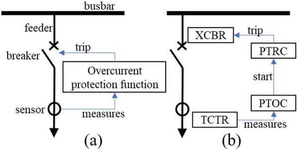
Figure 1 Simple protection function (a) and LN decomposition (b).
The objective of the protection function is to isolate the feeder from the busbar if an electrical fault occurs on the feeder. A current transformer is used as a sensor to measure the current on the feeder. The most common protection function is the overcurrent protection which compares the sensor measure with a given threshold and will send an opening command (a trip signal) to a circuit breaker if the threshold is crossed.
A possible decomposition of the protection function in standard LNs is as shown in Figure 1(b): a LN “current transformer” (TCTR) provides current measures to a time overcurrent protection (PTOC). In case of a fault, PTOC will activate a trip conditioning LN (PTRC) which will issue the trip command to the circuit breaker LN (XBRC).
Communication requirements between LNs, including timing requirements, are provided by the Piece of Information for COMmunication (PICOM). Several thousand PICOMs are specified for all the allowed LN interconnections [1].
The LN/PICOM specification does not impose a particular implementation on the actual hardware. A protection function does not need to be implemented on a single physical device. The LN used by a protection function may be distributed on several physical devices. Depending on the implementation, the PICOMs will be mapped to inter-process communications on a single device or to network flows. Physical devices, which are called Intelligent Electronic Devices (IEDs), are very variate in terms of available sensor and actuator hardware interfaces and available LNs. Most commercial IEDs can be customized. In general, an IED will support LNs corresponding to one or several protection functions (like overcurrent, thermal, distance protection) and a variable number of sensor/actuator interfaces and/or network interfaces. The combination corresponds to a typical electrical application (like transformer or generator or motor protection). An IED dedicated to measurement (i.e., no protection function LNs, only sensor/actuator interfaces) is called a Stand-Alone Measurement Unit (SAMU).
In Figure 2 two possible implementations of the simple protection function are shown: centralized on a versatile IED or distributed using a SAMU with breaker control capabilities and a protection IED.
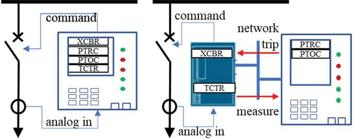
Figure 2 Two possible implementations: single IED or distributed.
Modern electrical grids heavily rely on distributed implementations and there are many reasons for this choice (see, for example, [2] for details). One of them is that network communication makes the sensor information available to many consumers without extra sensor wiring and allows the deployment of many new applications requiring power grid data such as power quality or metering. Another reason is that smart-grids have to optimize production, distribution, consumption, energy storage, energy mix and increase the availability of the electrical network. This requires more and more information available so, clearly, the data networks are a key element for the electrical network performance.
2.2 IEC 61850 Communication Protocols
Although serial-line communication is supported by IEC 61850, we will focus uniquely on Ethernet-based communication. IEC 61850 specifies three mappings to three communication protocols which correspond to the three main types of data flows in a power grid: local regular sampled values of sensors, local event transmission and remote control-room communication (supervisory control). Thus, two local Ethernet non-IP and one TCP/IP communication are defined. The TCP/IP-based protocol is Manufacturing Message Specification (MMS) [3] and the Ethernet non-IP protocols are Generic Object-Oriented Substation Event (GOOSE) [4] and Sampled Measured Values (SMV) [5]. Three logical levels of communication are present: remote TCP/IP between Supervisory Control and Data Acquisition (SCADA) and Protection IED [4], local (bay) communication between IEDs and process bus communication between SAMUs and IEDs. Figure 3 shows the respective communication levels and protocols.
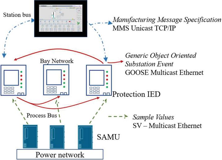
Figure 3 Communication levels and protocols specified by IEC 61850.
GOOSE protocol is designed for grid event propagation between IEDs like transmission of a trip event. SMV is designed for the periodic broadcasting of sensor measures by the SAMU.
The three communication levels do not necessarily correspond to three different networks although the standard recommends network segmentation and isolation as the three types of traffic have different requirements: low volume weak real-time for MMS (around 10 kbps per IED traffic and 100 to 1000 ms response time), average traffic and hard real-time for GOOSE (1 kpbs per flow with bursts at 1 Mbps in case of events and 3 ms response time) and heavy traffic hard real-time for Sample Values (SV) (around 5 Mbps per measurement point and 4 ms response time). The typical Ethernet connection available on a commercial IED is Fast Ethernet 100 Mbps. This is mainly due to the limited resources available on IEDs.
2.3 Real-time in IEC 61850 Communications
It is quite obvious that different data flows will have different real-time requirements according to their use in the electrical automation application. For instance, the data flows directed to the operator console will have low real-time requirements as the operator reaction time is very high (more than 1 s). Then, a hard real-time constraint on this traffic will be pointless. Therefore, the rationale employed by the 61850 standard is to deduce the traffic real time constraint from the real-time requirement of the electrical automation function. As a 61850 function is defined by a set of interconnected LNs and the communication between the LNs is described by the PICOMs, the real-time constraints are expressed at the specification level and not at the network or protocol level. Therefore, different flows carried by the same protocol type (GOOSE for instance) and sharing the same network (bay network, for example) may have different real-time requirements. Such that a trip signal carried by a GOOSE protocol will require a different transmission delay if used by a local (fast) protection function a remote (slow) protection function. For fast protection functions, reaction time is supposed to be less than a quarter of the cycle of the electrical signal (i.e. 5 ms for a 50 Hz electrical network or 4 ms for 60 Hz) while for slow protection function it is supposed to be in the order of half a cycle (10 ms for 50 Hz and 8 ms for 60 Hz). Then the chosen application to application transfer real-time constraints are 3 ms for fast protection functions and 10 ms for the slow ones.
Based on similar reasoning five more transfer real-time constraints ranging from 20 ms to over 1 s where defined for less demanding traffic. For the object of our study, the sample values data flows as they are used for protection functions the 3 ms and 10 ms transfer time requirements will apply. The 3 ms transfer time includes the computing time of the protection function on the IED. Of course, this time depends on the hardware and manufacturer and it is generally not specified but calculation examples in the standard assume computing times as high as 1.2 ms. Typical network latency is assumed to be less than 1 ms.
The 61850 does not explicitly specify a traffic jitter requirement (excepting for the time synchronization) but, the sample values traffic is required to be such that the electrical automation function behave “bumpless” that means there is no discontinuity of the calculated values due to network perturbation. As the computation algorithms and calculated values vary from one electrical automation function to another, an absolute jitter limit cannot be specified.
In our study we evaluate two network architectures with respect to the variation of the jitter. A performant network architecture shall show small jitter variation when the number of connected devices and flows increase.
2.4 High-availability Automation Networks
Due to the criticality of data flows in a power grid, the use of high availability networks like Rapid Spanning Tree Protocol (RSTP), Parallel Redundancy Protocol (PRP) or High-availability Seamless Redundancy (HSR) is recommended. High quality IEDs are often equipped with up to three redundant interfaces for process, bay and SCADA communications. Some of the SAMUs available on the market cannot be configured otherwise than for a redundant network. When flows with different real-time requirements share the same network, the use of VLAN is also highly recommended.
Although there is no “best choice” of a solution between RSTP, PRP and HSR, due to the long recovery time, RSTP is not suitable for bay and process communication (GOOSE and SMV).
Both HSR and PTP can be used for process bus and bay network. In practice, HSR seems to be more suitable for process bus communication (SMV to IED) as it does not need supplementary interconnection equipment and therefore is cheaper for simple network topologies, while PRP is most suitable for station communication (IED to IED) while it allows complex topologies.
In our study we are interested in the compared real-time performance of HSR and PRP networks for process bus communications. The next two sections are dedicated to short presentation of the two solutions.
2.5 HSR Networks
HSR is one of the two protocols described in IEC 62439-3 [6]. The network topology is a ring built by the interconnection of nodes having two ports operated in parallel (Doubly Attached Node with HSR protocol – DANH). A source will duplicate every frame, add an identification tag “A” or “B” and send each copy of the frame on an Ethernet port. A destination will receive the two copies, remove the tag keep the first arrived and destroy the second. All nodes are forwarding frames from one port to another except if they already sent the same frame into the same direction. A Singly Attached Node (SAN) may participate to the ring if they connect to a REDundancy Box (RedBox). Several SANs may connect to the ring via the same RedBox and a switch. The RedBox is periodically broadcasting into the ring all the MAC addresses seen on the external interface. Then the RedBox may be used to interconnect the HSR ring with a regular LAN. A basic HSR ring configuration is presented in Figure 4.
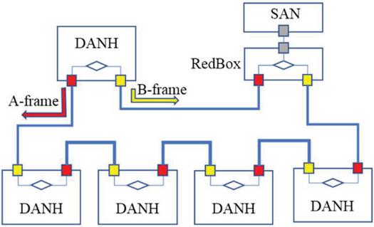
Figure 4 HSR ring including DANH nodes and a RedBox.
Note that HSR does not specify a real-time traffic scheduling algorithm, determinism is not guaranteed by design. For optical rings a less than 50 ns jitter is expected for each converter. Latency will increase with the number of connected DANHs.
2.6 PRP Networks
PRP networks are also specified in IEC 62439-3 [6]. The topology is a dual LAN. Doubly Attached Nodes with PRP (DANP) connect to both LANs. As in HSR case a source duplicates every frame and sends a copy though each LAN. The destination keeps the first arriving copy and destroys the second one. The two LANs can be regular Ethernet LANs or redundant (RSTP or HSR). They do not have to be identical and can be constructed with regular Ethernet switches. PRP networks supports cohabitation with non-redundant Ethernet frames, therefore a SAN may connect to the network through a RedBox or directly. However, there is no connection between the two LANs and frames never pass from one LAN to the other. A typical PRP network is shown in Figure 5.
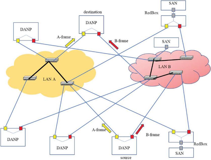
Figure 5 Dual LAN PRP network including DANP and SAN connected directly or via RedBox.
On the one hand, compared to HSR, the PRP solutions are more expensive due to the presence of LAN interconnection networks. On the other hand, the flexibility of the topology comes with a cost in terms of determinism: if the two LANs are not identical the transmission times of A-frames and B-frames will be different. This is particularly important when time synchronization frames like IEEE 1588 Precision Time Protocol (PTP) are sent through a PRP network. As the electrical applications may require a clock synchronization with a precision of a few nanoseconds, transmission times have to be very well known and offset have to be adjusted for each LAN in the PRP network.
For both HSR and PTP the jitter has to be kept as low as possible. In our study we used a separate network for the time synchronization signals in order to avoid cross influence of the jitter on both PTP and SMV but this point has to be addressed in the future as next generation substations will use one single network for process bus data and clock signals.
3 Experimental Workbench
Access to real substation automation network is difficult due to their critical mission and industrial secret. Moreover, as we intend to test attacks scenarios it is clearly impossible to experiment on a real electrical substation. Using the available material of our SCADA cybersecurity lab G-ICS [7], we built a small substation automation prototype connected to a simulated electrical grid using our hardware-in-the-loop simulation system [8].
The considered use-cases are reproduced following the reference topologies 7.3.2.3.6 (Process bus as a dual star) and 7.3.2.3.9 (Process bus as a single ring) and the case studies from IEC 61850-90-4 technical report [9].
3.1 Use-Cases and Topology
The two test workbenches are presented in Figure 6 (HSR) and Figure 7 (PRP). Up to eight IEDs are used: a protection IED, a control IED and six SAMUs.
For the HSR workbench the eight IEDs participate to an optical HSR ring on multi-mode 100 Mbps fiber optic. The six SAMUs are active DANH while the two IEDs use a passive DANH extension card (only receiving and forwarding frames). A RedBox is also connected to the HSR ring. It will be mainly used for external traffic observation and attacks. The two IEDs have also two other redundant network interfaces: one that is used for real time communication with other IED in a PRP network and a second one for the traffic with the control room in an RSTP network. The full workbench includes two other protection IEDs and a SCADA, but for the scope of this paper only the four participants to the HSR ring are relevant. In accordance with the classification of the IEC 61850 standard, this use-case is relevant for a medium size distribution substation (six IEDs or more).
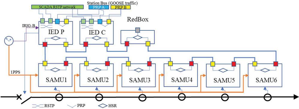
Figure 6 Electrical and topological view of the HSR test system.
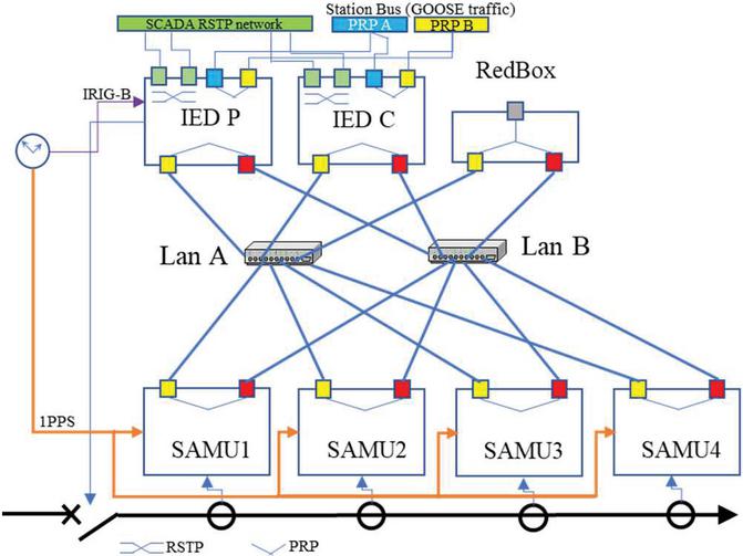
Figure 7 Electrical and topological view of the PRP test system.
The protection IED is a distant protection. It uses measurement points (current and voltage) and estimates the location of a fault based on line impedance measurement or current measurement. In our setup the distant protection uses the measure point of one of the SAMUs and pick-up on overcurrent. The control IED is not implementing a protection function. It is used for interlocking of protection IED. That means, it is checking that the joint state of the protection IED and circuit breakers is coherent and that changes in the state of breakers will not violate the safety functions. It uses the measurement point of the second SAMU. Both IEDs have internal supervision functions activated which check the internal status of the IED and also the sensors status; they may block the protection function on failure detection.
A time source is supplying IRIG-B [10] time synchronization to IED and one pulse per second (IRIG-H 1PPS) signal to SAMU. The choice of the two protocols were imposed by IED capabilities.
The IED brand is irrelevant for the study while we focus on IEC 61850 SMV protocol vulnerability not on manufacturer implementation. For the sake of detail, we mention that the protection IED is a Siprotec 5 7SA86 while the control IED is a Siprotec 5 6MD85. Both IEDs have a firmware version 7.54 and connect to HSR ring via the PB201 extension module. They are programmed with Digsi5 version 8.00. Both SAMUs are Merging Unit 6MU805 firmware version 4.03.05 and programmed with Digsi4 version 4.94.
The RedBox and time server are both RuggedCom. RedBox is a RSG950G firmware version 3.11.7. The IRIG-B and 1PPS time signals are generated by the RMM2431-5PTP module of a RSG2488 switch firmware 5.0.0. As SAMU time synchronization input is optical, a Meinberg TTL to FO converter is inserted between the RMM2431 and the SAMU.
The dynamics of the physical process are not important for our study as we are interested in how an attacker may inject corrupt data (like false faults) into a healthy system. Then a steady normal evolution of the measures is enough for the electric grid simulation. We use a simple client for our hardware-in-the-loop simulator to set steady values of the measured values. The details of the system and the software are available on the git repository.1
The PRP workbench uses the same IED and SAMU. The two LANs are simple identical star networks built around 61850 process bus qualified switches. Although any switch can be used in a PRP network some manufacturers qualify their equipment for low latency. As only 8 optical ports were available on our switches we included only four SAMUs in the PRP workbench. The 8th port is used for traffic monitoring. The switches are RuggedCom RST2228 with RMM2942-4LC2 optical modules.
3.2 Sample Values Calculations
The SMV frames are multicast Ethertype frames of type 0x88ba. There are 512 reserved multicast addresses from 01-0C-CD-04-00-00 to 01-0C-CD-04-01-FF. Each flow is supposed to use a different multicast address that receivers should subscribe to. SMV supports VLAN, so up to 4 VLAN-tag bytes might be added after the Ethernet header. If using HSR ring, the Ethertype is changed to HSR (0x892f) and six bytes are added storing the original Ethertype, the sequence number end routing information for bridging with PRP networks. If using PRP the Ethertype does not change and six bytes are added at the end of the frame containing the PRP sequence number (2 bytes), the LAN identifier (4 bits), the length of the payload in the original frame (12 bits) and a protocol identifier (0x88fb).
The Application Protocol Data Unit (APDU) has a variable size and format, which is described using ASN.1 BER [11] encoding rules. Then the information in the APDU is formatted as Tag/Length/Value in accordance with IEC 61850-9-2. The general APDU structure is presented in Figure 8 and contains at least a control field and service data unit (sampled data).
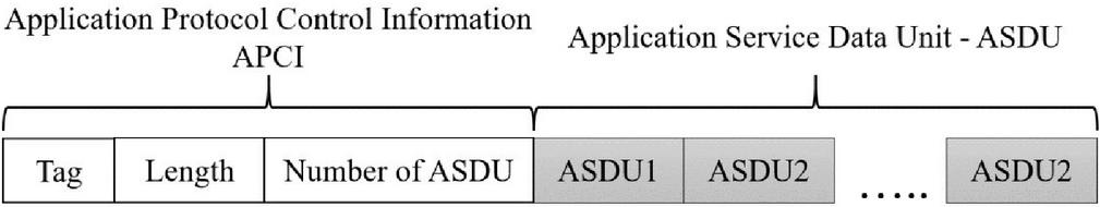
Figure 8 General APDU structure.
A precise Application Service Data Unit (ASDU) structure for SAMU is specified in UCA implementation guideline [12] (known as IEC 61850-9-2-LE). Measured values are sent together with sampling quality (four bytes value and four bytes quality) information, a string identifier, synchronization status and configuration version. For simplicity we illustrate the frame format on a Wireshark captured frame in Figure 9. One can note that there is no time stamp in 9-2-LE format. The only identification method available is the simple smpCnt field which is increased at every transmitted frame and overflows at 3999 (i.e., every second at a 4 kHz sampling rate).
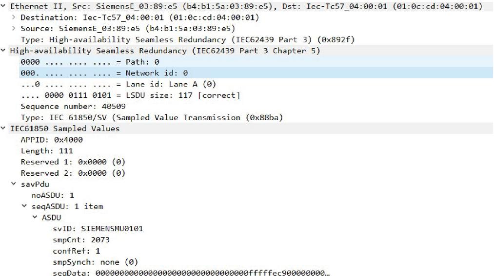
Figure 9 SMV frame with 9-2-LE ASDU format and HSR field.
In summary, for four current and four voltage samples, a SMV frame contains 112 bytes at the data link layer level plus four bytes, if VLAN is used, plus another six bytes, if HSR ring or PRP dual LAN is supported, plus the length of the identifier string. In our example, in Figure 9, there are 13 bytes in the identifier string, no VLAN support, but an HSR tag is added. Then, the SMV frame is 131 bytes long at Layer 2 or 143 bytes at Layer 1 (we add the eight bytes preamble and SFD and four bytes FCS removed by Wireshark).
Elementary calculations show that at a rate of 4000 frames per second a SMV flow uses at least 4 Mbps (without VLAN tags, outside the HSR/PRP network and one-byte identifier). Our SMV flows will use 4.384 Mbps outside the HSR ring/PRP LAN and 4.576 Mbps inside the HSR ring or PRP LAN. The interarrival interval between two frames of the same SMV flow is expected to be of 250 s and it is expected to be deterministic.
At 100 Mbps a SMV of 143 bytes length will be transmitted in 11.44 s plus 0.96 s interframe gap in FastEthernet. Simple arithmetic shows that at most 20 SMV flows may be transmitted in a 100 Mbps HSR ring. Actually, this is overestimated while it is not considering the non-real time traffic that may be present. This includes the supervision frames sent by all active nodes plus any other sporadic messages.
For the PRP the calculation might be more complicated as the links between the switches does not need to have all the same capacity. If we assume that all the links are identical (which is the case for our network) the same calculations as for HSR will hold.
3.3 Performance Measurement
The purpose of the measurement campaign is to check the traffic determinism provided by the HSR and PRP communication networks. Of course, one of the parameters of interest would be the end-to-end transmission delay. Unfortunately, the 61850-9LE SMV are not time-stamped. Therefore, we cannot measure the transmission delay.
Transmission delay puts aside the other important parameters from the point of view of the electrical application determinism of the traffic, i.e. the constant interframe arrival time. Because the SMV frames carry current measurement samples, and on the receiver side the electrical application has to rebuild the original signal timely, variations in the interarrival interval frames are important. In RFC 3550, for the characterization of the real-time traffic, the interarrival jitter is defined to be the “mean deviation (smoothed absolute value) of the difference in packet (or frame in our case) spacing at the receiver compared to the sender for a pair of packets” [13]. According to [13] the difference in frame spacing for a pair of frames is defined as:
Where and are the reception times of the packets while and are the emission time stamps of the packets. Then the jitter is the average of the absolute values of . In [13] an online estimator is proposed.
| (1) |
with some positive number. If then , i.e. the jitter estimator equals the absolute measure difference in packet spacing. In that case any noise on the measure is included in the jitter expression. If then the noise on the measure is filtered and smoothed but the estimator will follow with a delay the changes in the packet spacing duration. Use of the estimator is particularly interesting in traffic control applications. For our performance evaluation study, the jitter evaluated by (1) is less meaningful than the study of difference in frame spacing for a pair of consecutive frames. In RFC 4689 jitter is defined as the absolute value of the difference in frame spacing between two consecutive frames. As we are interested not only in the average value of the difference in frame spacing but also into the statistical properties of the distribution of these values we adopt, in this paper, the definition of jitter as the frame interarrival deviation (and not the absolute value). We allow then negative values of the jitter. Then, in this paper the jitter will use the formula:
Timestamps are not available for SMV in our experiments but as we are interested by the end-to-end application jitter we may assume that the emission times are deterministic (at least compared with the network) then s. Moreover, in order to allow comparisons with other deterministic durations we consider normalized values.
Then, for our performance evaluation, we use the following expression for the normalized jitter.
| (2) |
Where is 250 s unless otherwise stated.
3.4 Measurement Protocol
We used two different traffic measurement points: one on the external RedBox interface a second one using a network tap inside the HSR ring either on one of the directions or on one of the optical links in one of the PRP LANs. The measurements on the two points were performed independently. We used a passive optical tap from Keysight.2 We then used a fiber/copper converter (Allied Telesis DMC 100/LC) to interface with the traffic capture computer.
Observed traffic characteristics in the two points were quite the same. We chose for the experimental results measures in one or another measurement points according to the use-case.
3.5 Experimental Results3
We have conducted several experiments on both HSR and PRP architecture in order to study the influence of the number of SMV flows on the traffic deterministic properties. While the interconnection equipment is not the same for HSR and PRP configurations we do not attempt a direct comparison of the rough statistical values. We are mostly interested by the deterministic performance degradation when more SAMUs are connected on the same process bus.
3.5.1 Measurements on a single flow
Our SAMU can be configured in four different transmission modes: line mode (no redundancy), HSR, PRP and RSTP. Our first experiments consist in comparing the performance of one single SAMU in various configurations. We ignore the RSTP mode since the recovery is more than 40 seconds. We measure the frame spacing statistical properties. A histogram for linemode is shown in Figure 10. In all histogram representations in this paper values on abscissa correspond to the normalized jitter defined in (2). On the ordinate we represent the proportion of points with a histogram bin.
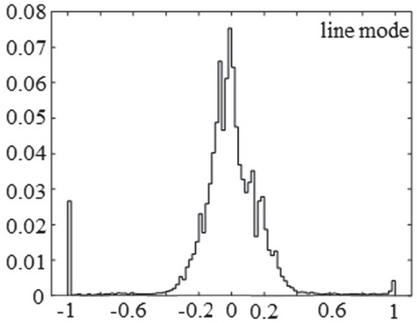
Figure 10 Histogram of normalized frame spacing for a single SMV flow in line mode.
Captures in the line mode and PRP for single SAMU experiments were made in a direct connection between the SAMU and the traffic capturing computer without any intermediary connection device.
For a perfectly stepped SMV flow all values would fall into the bin around 0 (i.e. 250 s between frames). The mean value of the normalized interarrival time is 0.0000013 for a data set of over 100000 frames (around 24 seconds traffic capture) and that is quite perfect. Negative values in Figure 10 correspond to frame spacings inferior to 250 s while positive values to spacings longer than 250 s. Values in the bin starting in -1 correspond to a value of frame spacing of zero which is obviously the result of the limited WinPcap timestamping precision.4 The shortest expected normalized interarrival value is 0.948 (as a SMV frame duration is less than 13 s). However, 2.7% of the measured intervals are less than 0.948 (see the first bin in the Figure 10 histogram) and 2183 values out of 105906 equals to zero. We tested several configurations for WinPcap time source but, for the moment, we did not find a satisfactory solution to improve WinPcap precision so this point has to be further clarified in the future. Due to this biased capture timestamp we consider our measures as a worst-case lower bound of the SMV jitter. At the other extremum of measured values there are 1295 frame spacing values superior to 1 in Figure 10, i.e. frame spacings superior to twice the expected deterministic pace. There are even 1500 spread between 1 and 10 not represented in Figure 10 while the bins were too small. The absolute average deviation from the deterministic spacing is 0.172, i.e. 43 s and the standard deviation is 0.346.
In PRP mode the performances are not very different from the line mode (Figure 11 PRP graphic). This is quite normal as the traffic capture is the same in the two cases (direct connection between the SAMU and the computer).
In HSR mode the performances are somehow better compared to the line mode and PRP. Frame spacing value are less spread (standard deviation 0.21 against 0.34 for PRP and line mode) but the absolute average deviation is comparable with PRP and Line mode 0.16. Anyway, it seems that the transmission in the ring with the presence of the RedBox and the two IEDs is improving the regularity of the frames. There is however an important spread of values. There are 11 (out of 108509) values between 1.5 and 2.3 (i.e. an interarrival time between 625 and 825 s) not displayed in Figure 11 while the height of the corresponding bins is too small to be visible on the figure. The shortest expected normalized interarrival value is 0.948. However, 0.13% of the measured intervals are less than 0.948 (the first bin in the Figure 11 HSR histogram) and 22 measures are 1.
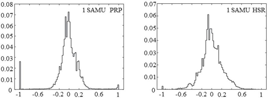
Figure 11 Histogram of normalized frame spacing for a single SMV flow for PRP and HSR.
There are several points of interest to be discussed concerning this experimental real-time performance assessment. The first one is to understand the source of this important variability of interarrival times and its consequences on the automation functions. As Line mode and PRP measures were acquired in a direct link connection the variability is not due to interconnection devices. In HSR configuration the presence of the interconnection device (RedBox) seems to improve the performances. It is difficult to explain this variability as the frames are not timestamped by the SAMU. The inspection of data sets showed that traffic other than SMV represents less than 0.1% of the capture and are only short ARP frames. Inside the HSR ring some HSR supervision frames are present, but this is also an insignificant traffic as there is a short (70 bytes) frame per DANH every two seconds. We assume that the interarrival times variability reflects the limit of the real-time performance of the SAMU network card. Adding time synchronization did not change the performance in a significant way (less than 1%). This is not surprising while our measurement concerns a short time performance evaluation (less than 30 seconds) while the time synchronization corrects the long-term internal clock drift. The fact that adding the 1PPS time synchronization does not improve the short term measured jitter simply means that the internal clock of the SAMU has a very small drift that does not manifest on short duration.
Table 1 below synthesizes the experimental results for the three configurations.
Table 1 Experimental measures for one single SMV flow
| Experiment | Variance | Standard Deviation | Absolut Average Deviation |
| Line Mode | 0.120 | 0.347 | 0.172 |
| HSR 1 flow | 0.047 | 0.217 | 0.160 |
| PRP 1 flow | 0.111 | 0.334 | 0.169 |
The crucial question is how the jitter affects the protection functions behavior. During our measurement sessions in HSR rings two IEDs (one control and one protection) were present, both of them using the measures in the SMV flow. There was no alert raised by the IED concerning the quality of the samples. We also checked that the PRP SMV flows do not raise any alert about the quality of the measures on an IED connected with the SAMU.
This is due to the fact that the protection and control functions do not use a 4 kHz sample rate. According to IEC 61850-5 Edition 1, protection and control functions requires only 480 samples/s, i.e., only 1/8 samples from the actual SMV flow. Edition 2 of IEC 61850-5 does not specify an exact throughput needed by protection functions but simply says that the jitter characteristics depend on the application. That has an important impact on the evaluation of the jitter. The same measures of the jitter variation, taking only one out of eight samples from the same dataset, show a standard deviation of interarrival duration reduced 10 times for both HSR and PRP. The interarrival duration is between 211 and 300 s (0.155 to 0.198 normalized intervals) for HSR while for PRP 97% of the values lay between 208 to 300 s and there are still 3% outside this interval. The corresponding histogram is shown in Figure 12. We kept the same interval and number of bins as in Figure 11 to allow the comparison between the histograms.
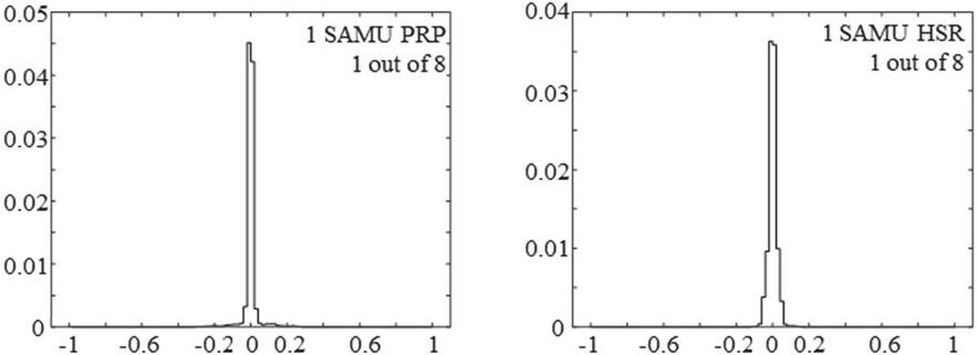
Figure 12 Histogram of normalized interarrival times as seen by protection and control IED (one out of eight samples).
The synthesis of the results while taking only one out of eight samples from the flow is presented in Table 2. We focus only on redundant topologies RSTP and PRP. Values in Table 2 are not intended for a comparative performance of PRP and HSR while the interconnection equipment is not the same but as a basis for the further study of the evolution of the performance in each network.
Table 2 Experimental measures for one single SMV flow when tacking one out of eight samples
| Experiment | Variance | Standard Deviation | Absolut Average Deviation |
| HSR 1 out of 8 | 0.001 | 0.022 | 0.015 |
| PRP 1 out of 8 | 0.003 | 0.055 | 0.016 |
3.5.2 Measurements on HSR networks
We are interested now in the interaction of several SMV flows sharing the same HSR ring and the effect on the jitter. We gradually increase the number of connected SAMUs and subsequently the number of SMV flows from 2 to 6. The flows have identical characteristics (frame size, sampling rate and priority). The results show that the interaction between flows is very important. We study the statistical performance of one of the flows in presence of several others. As the flows are identical any flow can be chosen for study. Statistics for one flow when two or six other flows are present is represented in Figure 13. Although the average value of the interarrival duration is still very close to 250 s, jitter is greatly increased. Even with only two flows, the standard deviation is multiplied by three (0.68 versus 0.217 for a single flow) and the maximal interarrival interval is greater than 1.3 ms (5.3 normalized value). Over 2% of an interarrival times in each flow are superior to 1 ms (normalized value of four) and 10% are very short (note the high bin around 1 in Figure 13). The performance degrades as more SAMUs are added to the ring. For six SAMUs present the standard deviation is close to 1 (0.953) i.e. almost one frame spacing interval. Moreover, we can remark on the histogram in Figure 13 that almost none of the measures are close to the nominal value (less than 0.2% of the measured values are into the bin around 0). We note that the average spacing is still close to 250 s but the absolute average value of the jitter is 200 s (0.8 normalized value) that means that in average, two consecutive samples will come either very close (50 s) or intervals of almost double the nominal interarrival value (450 s). Full results for the 5 experiments are presented in Table 3.
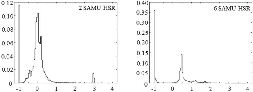
Figure 13 Histogram of normalized interarrival times for a SMV flow in a two-flow, respectively six-flow measurement experiment.
Table 3 Traffic performances evolution in HSR network as a function of the number of SAMUs
| Experiment | Variance | Standard Deviation | Absolut Average Deviation |
| 1-flow HSR | 0.047 | 0.217 | 0.160 |
| 2-flows HSR | 0.462 | 0.680 | 0.378 |
| 3-flows HSR | 0.177 | 0.420 | 0.220 |
| 4-flows HSR | 0.132 | 0.363 | 0.207 |
| 5-flows HSR | 0.458 | 0.677 | 0.369 |
| 6-flows HSR | 0.909 | 0.953 | 0.807 |
The SMV flow seen by protection and control IED (one out of eight samples) has also degraded performance. In the two-flow experiment, performance is still quite correct (less than 0.003 standard deviation with interarrival times between 184 and 328 s). In turn, in the six-flow experiment jitter performance is still low. Standard deviation is reduced only 4 times and there are still some frame spacing close to zero. The corresponding histograms are presented in Figure 14. Measures were performed with 34000 frames per flow (more than eight seconds traffic capture). Table 3 provides the statistical results. We note that even in the six-flow experiment the IED does not alert about the quality of the measures. Protection function requirements in terms of jitter seem to be quite low.
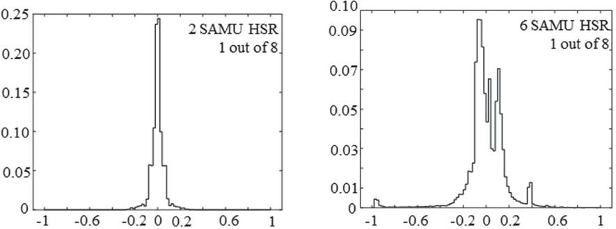
Figure 14 Histogram of normalized interarrival times as seen by protection and control IED (one out of eight samples).
Table 4 Statistical results for “1 out of 8” frames experiments
| Experiment | Variance | Standard Deviation | Absolut Average Deviation |
| 1-flows HSR 1 out of 8 | 0.001 | 0.022 | 0.015 |
| 2-flows HSR 1 out of 8 | 0.004 | 0.066 | 0.024 |
| 3-flows HSR 1 out of 8 | 0.005 | 0.074 | 0.024 |
| 4-flows HSR 1 out of 8 | 0.059 | 0.243 | 0.102 |
| 5-flows HSR 1 out of 8 | 0.067 | 0.258 | 0.057 |
| 6-flows HSR 1 out of 8 | 0.062 | 0.248 | 0.119 |
In all the experiments we measured the SMV flow from the same SAMU in order to avoid errors induced by possible different hardware performances of the devices. We also compared the measures between the different flows in the same setup in order to see if the results are different for example due to the different number of hops (retransmissions) between the emitter and the measurement point. For the two-flow experiment there are 10 % difference between the standard deviations of the two flows. As the number of flows increase the differences between the different flow performances are smaller. Such that for the six-flow experiments there is less than one percent difference between the standard deviations measured on different flows.
One can see that the evolution of standard deviation and absolute deviation in Table 3 is not monotonic when the number of SAMUs increase. For the moment there is no clear explanation for this behavior. We conjecture that, while adding a new SAMU in the ring we add a jitter source also a deterministic flow. Such that a new SAMU added to the ring will act both as a perturbation as it adds some jitter to the existing flows but also as a regulator of flow while adding a real-time cadence. The result of the combination of the two factors depends on the number of flows and DANHs. This conjecture is enforced by the observation that the standard deviation evolution of the standard deviation is monotonic in Table 4: on longer periods (cycles of eight frames) standard deviation is increasing when the number of flows increased. Then, even if locally between two consecutive frames the jitter may be improved when adding a SAMU to the ring, long term performance of the flow is degraded.
We conclude this section with the remark that the lack of real-time traffic scheduling mechanism in HSR has an important impact on the jitter performance. For the moment we do not have a simple mathematical model to explain this behavior of the jitter. A multi-class closed queuing network model may provide help in understanding the evolution of the jitter in an HSR ring as the number of flows and DANHs increases but this is out of the scope of the present work.
3.5.3 Measurements on PRP networks
We conducted similar experiments on a PRP network, i.e. we added gradually more SAMUs in the network configuration shown in Figure 20. Then we captured the traffic on one of the copper interfaces of the switch. As we had a limited number of optical interfaces available on the switch only four SAMUs were included into the experiment. Analysis of the captured traffic for various numbers of SAMUs connected shown that the LAN switch has a regulation effect on the traffic. The SMV performance does not vary significantly if one or the four SAMUs are connected. Performance is less good than the measures presented in Section 3.5.1 while it includes now a jitter added by the switch. When considering only one frame out of eight as seen by the IED, the performance is comparable to the case of one single flow. Histograms of the measures represented in Figure 15 and the statistical measures in Table 4.
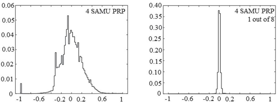
Figure 15 Histogram of normalized interarrival times for a SMV flow in a four-flow PRP experiment.
Table 5 Statistical results for the PRP experiments
| Experiment | Variance | Standard Deviation | Absolut Average Deviation |
| 1-flow PRP | 0.088 | 0.297 | 0.196 |
| 2-flow PRP | 0.062 | 0.250 | 0.160 |
| 3-flow PRP | 0.067 | 0.259 | 0.173 |
| 4-flow PRP | 0.054 | 0.233 | 0.166 |
| 1-flow PRP 1 out of 8 | 0.002 | 0.047 | 0.020 |
| 2-flow PRP 1 out of 8 | 0.001 | 0.027 | 0.016 |
| 3-flow PRP 1 out of 8 | 0.001 | 0.035 | 0.017 |
| 4-flow PRP 1 out of 8 | 0.001 | 0.028 | 0.015 |
Measures on the first line in Table 3.5 are not the same as in Table 1 as here a network switch is used. And it seems that the switch as a beneficial influence on the jitter. One can also observe that the standard variation is not varying too much when more SAMUs are added to the network. The fact that the 4-flow PRP performance is better that the other is not surprising: the switch acts as a round-robin server between the active interfaces. If only one interface is active the cycle switch cycle will be shorter and the output traffic will be similar to the input. When all interfaces are active and SMV flows are present the round-robin service mechanism of the switch will produce a more regular output. An ideal switching mechanism for SMV flows would be to force the round-robin period to 250 s.
We conclude that, from the point of view of jitter performance degradation, PRP networks will provide a better performance as the switches will act as a flow regulation device while, in HSR rings, interconnection devices such as RedBoxes and passive receiver DANHs will only add more jitter to the traffic.
4 Attacks on Process Bus
We consider two attack scenarios on SMV flows. The first one consists in injection of false measure data into the process bus. The second one is a quantitative attack (i.e. a network flood).
4.1 False Data Injection
As there is no authentication mechanism on SMV flows and frames are only identified by smpCnt counter field (see Figure 9), obviously, the protocol is vulnerable and false data injection is, in theory, simple to implement. The target of the attack would be to trigger a protection function and therefore a trip order to a circuit breaker occurring in a partial disconnection of a part of the power grid.
Practically, inserting false SMV data means that the attacker has to sniff the legal traffic, read smpCnt, then insert a frame with the smpCnt incremented before the legal frame with the same smpCnt value arrives. As frames with smpCnt less than or equal to the smnCnt of the previously received one are ignored, according to IEC 61850, the vulnerability seems easy to exploit.
Although the attack seems straightforward, some characteristics of the protection functions behavior and SMV flow characteristics have to be considered.
The corrupted frames must be injected inside the HSR ring or the PRP LANs. We consider separately the two redundant network architectures.
4.1.1 False data injection in HSR rings
For HSR there are two possibilities to inject data: either through the external interface of a RedBox or directly into the HSR ring. The second case is more difficult as it requires a specially programmed DANH. The attacker device has to support HSR and to counterfeit the HSR identifications: HSR sequence number and lane. Otherwise, the frame may be rejected by the HSR layer of the target. Timing is also an issue while frames arrive every 250 s in an optical ring. The entire attack chain: optical/electrical conversion, frame reading, decoding, counters modification, transmission, electrical/optical conversion has to be performed in less than 250 s. As this attack is difficult to implement we chose to inject the false frames through the external interface of a RedBox. Then, we do not need special hardware and we do not have to counterfeit HSR frame fields.
We conducted the experiment on a computer with a 2.90 GHz i7-4910 processor. A first attack attempt through the RedBox showed that the computing time is not fast enough to inject a SMV frame with incremented counter before the arrival of the legal frame. But, the counter verification is not strict. IEC 61850 allows several frames to be lost so it is enough to choose a counter value big enough with regard to the last legal frame counter value. Then, the false frame is accepted by the subscriber and all the frames with intermediate counter values are rejected. As the frame counter is reset every second, after the injection of a single false SMV frame the measurement system recovers in at most one second.
On another hand, electrical measures are naturally subject to noise. Protection functions will not pick up on a single sample superior to the maximal current. Often, protection functions are timed with variable timeouts ranging from millisecond to seconds. It follows that a single frame or even a very short sequence is not enough to trigger a protection function and, subsequently, a trip signal.
In our experiment we injected a false SMV flow through the external interface of the RedBox. We use the spoofed MAC address of one of the SAMUs as the sender. The attack program waits for the reset of the smpCnt of the legal SMV sequence then generates a false data flow with a SMV counter incremented of 1000. The flow is not real-time stepped, but simply sequenced with usleep system call function. The attack is implemented on a Linux computer with the free libIEC618505 development stack and libpcap-dev library. Code and capture dataset are publicly available at: http://lig-g-ics.imag.fr/mediawiki/index.php/Datasets.
The attack successfully triggers the protection function on the protection IED which generates a trip signal.
An even more harmful attack is developed on the same basis. Instead of a false measure superior to the overcurrent, we inject a flat zero value sample measure. This triggers the supervision function of the protection IED. As mentioned in Section 3.1 supervision functions survey the internal status of the IED and also the sensors status and block the protection function and therefore the IED will be out-of-order. The default timing of the supervision function on our IED is 10 seconds and, indeed, after 10 s of transmission of a false SMV flow the supervision function triggers and blocks the IED.
This second attack on the supervision function is more harmful while the IED cannot recover automatically after the attack contrary to the attack on the protection function. The IED is blocked by the supervision function and a manual reset is necessary.
4.1.2 False data injection in PRP LANs
For PRP, as a device may be directly connected to the switches, data injection is apparently simpler than in the HSR case. As the LANs are independent and the DANPs are only emitters or receivers and not relaying frames like the DANHs, there is no need for special hardware or network protocol stack to inject traffic. Moreover, as it is not from the standard that the receiver has to verify the PRP trailer, even a SAN can be used to inject false data. We choose not to exploit a possible weakness of the manufacturer implementation of the PRP protocol on the receiver side and we choose to use a RedBox configured in PRP mode to inject the false traffic. The attack was successful as in the HSR case. However, the timing might be a challenge while in the case of PRP the position of the attacker in the network is not indifferent. If the topology of the LAN is complex the distance between the attacker and the receiver IED may be longer in term of number of switch hops than the distance between the SAMU and the same IED. Then the extra transmission delay added with the processing time needed to forge the fake SMV made the attacker task difficult. In our case, as the LAN consisted of only one switch the attack was successful.
There is however a big technical advantage of PRP networks over HSR concerning the security. In HSR all DANHs in the ring have to forward all the traffic and the DANHs cannot be configured for ingress or egress traffic limitations. Switches used in LANs in PRP may include security measures and this is the case on modern switches like the one we used. Ruggedcom RST2228 allows port rate limiting with specific filtering for Broadcast/Multicast and static MAC address configuration. As SMV flows are multicast when security measures are activated the SMV diffusion may be directed only to legitimate destination. Such that SMV flows will be invisible to attackers situated to other points in the network. Also, as the ingress broadcasts can be limited on ports not supposed to send SMV, attacks will be rejected as false data injection needs to inject a continuous multicast flow.
Then, the conclusion of false data injection attack on process bus experiments is that PRP networks are clearly a better choice than HSR as switches can provide security controls which is not the case in HSR rings.
4.2 Quantitative Attacks (Network Flood)
Eventually, we test the resilience of the communication system in case of quantitative attacks. Given the conclusion of the previous section network flood attacks on PRP networks can be easily avoided with an adequate configuration of the switches. We therefore consider only the HSR case.
We inject a large number of frames thru the external interface of the RedBox and we observe the traffic inside the HSR ring using the copper network tap and the two optical/electric Ethernet converters. Although the type of injected Ethernet frames is not important we inject SMV traffic to the multicast addresses subscribed by the two IEDs. The idea is that we will test both the HSR infrastructure and the reaction of the IED when a large quantity of sensor data is received.
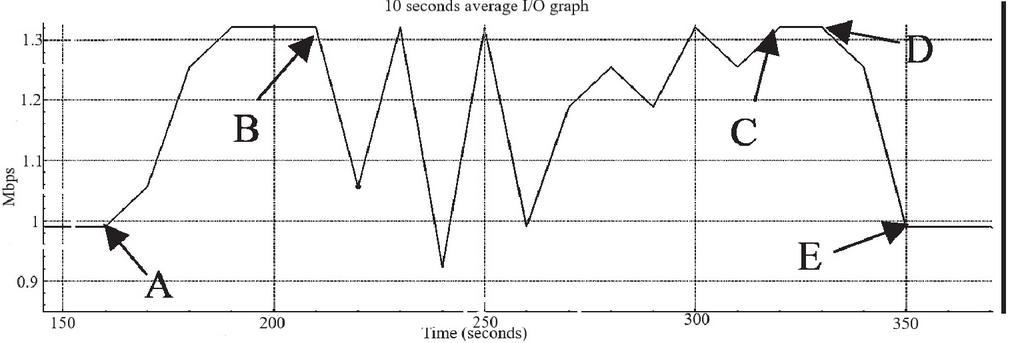
Figure 16 Evolution of the HSR supervision traffic during the quantitative attack (10 s moving average).
The HSR ring collapses at a global load approximately of 76 Mbps measured in Wireshark at Layer 2. That means around 81Mbps at Layer 1 (including preamble and FCS bytes). The two IEDs signal a failure of the measurement points.
The exact moment when the HSR ring starts failing can be seen if we trace the HSR supervision frames throughput. HSR supervision frames are 66 bytes long in Wireshark and normally each SAMU will send one frame every 2 s while the RedBox will send one frame every 2 s if no SAN is attached on the external interface and two frames every 2 s if a SAN is attached. That means a steady traffic of 990 bps if no SAN is attached and 1320 bps when a SAN is attached. Then, the attack timing can be followed on the HSR supervision traffic graph (Figure 16). At point A the attacker connects to the RedBox which starts sending two supervision frames instead of one. At point B HSR ring starts falling and some supervision frames are lost. At point C the attack stops and HSR ring recovers. Then, the attacker disconnects from the RedBox (D) and the ring comes back to the initial state (E). Note that, as the graph is a 10 s moving average, the real events occurred several seconds earlier than marked on the graph.
The total traffic graph is presented in Figure 17. Due to the important difference in volume between supervision traffic and total traffic the scales in Figures 16 and 17 are not the same. The approximate position of points B and C are indicated. Points A, D and E cannot be identified on the Figure 18 while the corresponding variation is too small compared to the SMV traffic.
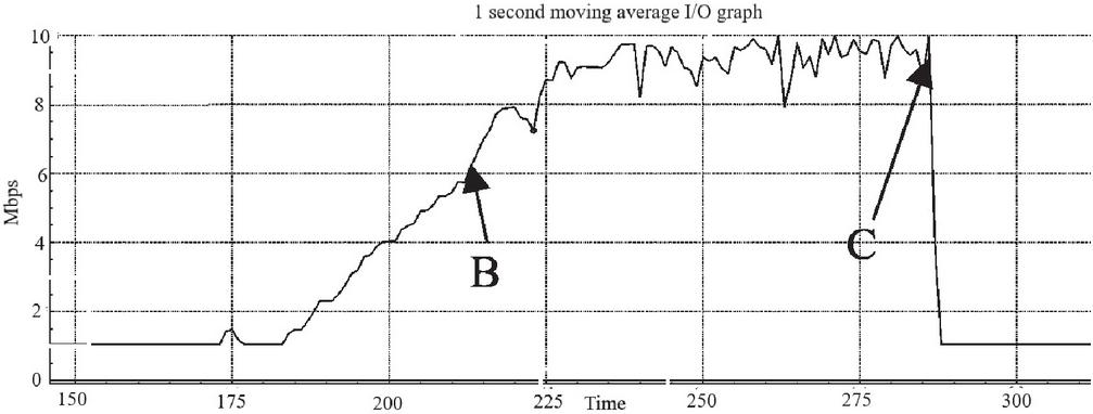
Figure 17 Traffic evolution during the quantitative attack (1s moving average).
The exact moment when the HSR ring starts falling may be identified on the traffic capture. Inspection of the dataset shows that at some point some Ethernet frames of unknown type are transmitted into the network (Figure 18). A byte inspection of the frames shows that they are actually malformed SMV frames resulting of a probable overflow of one of the internal buffers of the RedBox. The visible “data bytes” 0x75ab63 are part of the HSR tag, 0x88b4 is the SMV Ethertype and so on. The first malformed frame in the data set identifies the moment when the HSR ring is overflown.
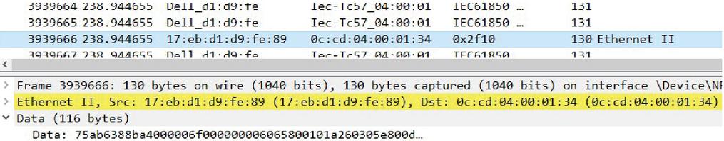
Figure 18 Malformed frames transmitted by the RedBox during attack.
Finally, in Figure 19 we present the impact of the attack on the legitimate SMV traffic. The graphic displays the throughput in frames/second of one of the two legitimate SMV flows. We can remark that up to 20 % of the traffic is lost at some moments during the attack. This explains the failures of the measurement points signaled by the subscribers (IEDs).
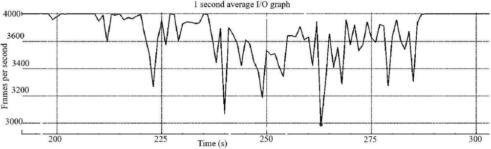
Figure 19 Effect of the quantitative attack on the legitimate SMV flow.
We conclude this section with a positive remark: despite the fact that the quantitative attack was successful and the protection function was affected, the HSR ring recovered fast after the attack and none of the network nodes (including the RedBox) needed to be manually restarted. Only the failure error of the measurement points on the IED had to be acknowledged. Note also that the attacks are exploiting protocol vulnerabilities, they are not specific to a manufacturer implementation.
However, summing up the conclusions on various experiments on HSR and PRP a clear conclusion arises: PRP networks are more resistant to attacks by data injections and flood thanks to the security controls deployed on the switches. On another hand, due to the ring architecture HSR networks are more difficult to defend even assuming that similar security controls will be deployed: MAC address filtering will not work as all MAC addresses in the ring has to be forwarded by all DANHs and multicast traffic limitation will drop indistinctly legitimate traffic and attacks as all the flows have to pass by all the interfaces.
5 Detection and Mitigation
Even if a PRP network may be efficiently configured to resist false data injection and Ethernet flood, detecting security policy violation attempts and reacting is important. For HSR ring, detection and mitigation are crucial as they are very vulnerable to such attacks.
Both false data injection and quantitative attacks can be detected by measurement of the traffic inside the HSR rings and PRP LANs. An interesting point is that early detection of attacks may be achieved with HSR/PRP supervision traffic survey. That may help detecting an attacker that connects to the external interface of a RedBox. A skilled attacker may avoid this detection if he connects using the MAC address of an already connected device.
Mitigation is an important point as the consequences of an attack are potentially critical. Even if detection is possible, the key is the reaction time. A protection function may be triggered by an attack in several tenths of millisecond or even in some milliseconds. Supervisory functions may be triggered in several seconds but this is a very short time interval for a human reaction. Therefore, we consider the automatic response in case of attack.
Electrical protection applications are designed to isolate or reconfigure a part of the electrical network in case of an electrical fault. On modern communication systems, network faults are also handled using high availability network topology. Cyberattacks are not yet included in the reaction mechanism in commercial devices even if there are several references in the literacy (see Section 6). Of course, an attack is not a fault, so, extending an electrical protection application to consider cyberattacks in the reaction loop is not immediate.
Our proposal is to use an Intrusion Detection System (IDS) alert which identifies the attack (false data or network flood attack) as an input to the electrical protection function. Then, the electrical protection application will issue the adequate reconfiguration control in order to keep the power grid operational or, at least, safe. Usually, a safe configuration for the power grid exists and the protection and control IED can activate the circuit breakers and switch the grid to a safe state. For example, if one of the measurement points is detected as compromised by the IDS, given the state of the other measurement points, the topology and the load of the grid, the estimator (control room) can figure out the electrical state of the compromised measurement point and reconfigure the protection application. The main issue is not how to reconfigure the protection application, which is purely an electrical engineering problem, but how to raise the alert signal from the IDS to the IED in an effective way and in a short time.
The best solution would be to implement a host IDS based on traffic measurement directly on the HSR interface of the IED. Unfortunately, given the high processor load and the limited resources of the IED this is not possible for the time being.
Then, a network IDS has to be used. Communication with IED has to be implemented via an IEC 61850 protocol. As an alert is an event, the adequate protocol seems to be GOOSE messaging on the bay network. In a previous work we specified such a 61850 intrusion detection function [14, 15]. The alert event transmitted by the IDS via the GOOSE messaging on the bay network may be directly used by IEDs to inhibit trip messages and to trigger reconfiguration of the electrical protection activation in real-time. Although, usually, the bay network is physically separated from the process bus, it can also be attacked and the GOOSE protocol is also vulnerable to false data injection [14]. In that case, a last resort alarm system can be used to send an alert directly to the control room via a secure protocol. This last solution has a less performance as the station bus used to communicate with the SCADA is not real-time. The complete reaction loop is represented in Figure 20.

Figure 20 Reconfiguration loop following a process bus cyber-attack.
5.1 PRP Implementation
We implemented the SCADA reconfiguration loop from Figure 20 for PRP networks based on a traffic measurement detection. Implementation is particularly simple as the switch can be used as a sensor. In IEC 61850-90-4 a data model for network bridges is specified. This data model is an alternative to the traditional Simple Network Management Protocol (SNMP) data model. The 61850 bridge model is selecting configuration and status variables relevant for electrical automation functions. The 61850 data objects are the Logical Nodes and they exchange information though one of the three 61850 communication protocols.
The LN of interest for traffic monitoring application is “Physical Communication Port” (LPCP) which is part of the group L of LNs (System logical nodes). Among the various status variables available into the node there are transmission and reception counters (RxCnt and TxCnt). There is an instance of LPCP available for each network port. As 61850 objects can be read by MMS requests the network switch integrates directly as a sensor in a SCADA system.
In our implementation, the SCADA is scanning periodically the LPCP status variables (including RxCnt and TxCnt) which are timestamped by the sensor (switch). The actual throughput of the ports is computed on the SCADA. When an attack is detected on the process bus an MMS command is send through the station bus (MMS write of a user variable) to the IEDs triggering the safe mode. The reaction time of this is MMS-based implementation depends on the polling period of the SCADA. In our implementation we were able to react in approximately 100 ms.
A faster implementation based on GOOSE is technically possible but commercial devices dos not support it. Among the status variables of the LPCP LN there are two which can be used to signal an overflow of input or output buffer of a port (InOv and OutOv). Status change of InOv can be used to trigger a GOOSE message to the protection IED. As end-to-end transmission time of a GOOSE is required to be less than 4 ms, such un implementation would provide a reaction time 20 times faster than our MMS based implementation. Currently there are two impeachments to the deployment of this solution. Firstly GOOSE communication is not yet implemented on the commercial switches. Secondly, although defined in the 61850 standard, InOv and OutOV status variables are subject of technical issues (Tissue 7766) in the standardization committee therefore they are not available on most current implementation. Therefore, for the moment the only possible implementation is the MMS-based one. A schematic representation of the two implementations is presented in Figure 21.
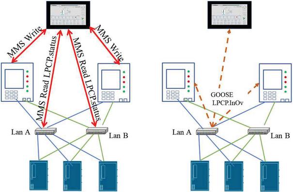
Figure 21 Two reaction loop implementations: MMS based and GOOSE based.
5.2 HSR Implementation Issues
The HSR implementation of an IDS is far more difficult. The 61850 bridge model is not supported on currently available RedBoxes. Implementing an IDS for HSR rings from scratch presents two issues: first, at least four network interfaces are needed as the IDS has to listen the two HSR lanes and communicate on the bay and station networks. Secondly, it has to be a real-time device as traffic measurement and bandwidth estimation have to be accurately handled. Currently there is no satisfactory supported hardware in the commercial devices. In the near future we intend to explore the feasibility of a “hybrid” solution, for example using an embedded RedBox module like RMM2972-2RNA. Even if the module itself does not support the 61850 bridge model, it can be installed on a RST 2228 who supports the bridge model. In such a way, a “slow” implementation, MMS-based, would be possible even for HSR networks.
6 Related Work
In this paper we tackle two different problems: traffic measurement in HSR and PRP networks and attacks on the process bus. Traffic measurement in SCADA systems and electrical grid communication network were conducted mostly to find regularity properties of the traffic (as periodic sensor reading or actuator writing) [16] or to analyze complex flow configurations and characterize the end-points and flow duration [17] in search for traffic patterns useful for security. HSR and PRP network performance was studied in [18] and [19] using a simulated network in OPNET. Propagation delay on HSR and PRP process bus was studied in [20] using a special prototype of RedBox and timestamped SMV which are not available in 61850-9-2-le. Real-time performance was studied on redundant networks for GOOSE protocol [21], but only the propagation delay was studied as this is the important performance parameter for GOOSE. Probably, the closer study to our work is [22], where the global protection function is experimentally studied with measures transported via an HSR ring, but the properties of the traffic itself are not considered. With respect to the existent state of the art, we consider that our study of jitter variation in HSR rings and PRP dual LANs is a novelty.
Concerning the attacks and detection in 61850 networks, the literacy is very rich. Specifically, on false data injection in power-grids, a recent survey [23] is listing model-based and model-free learning methods. All these algorithms are based on the prediction of the evolution of measures. They build a mathematical model of the dynamical evolution of the electrical network and they detect intrusions based on the deviations of the received SMV values from the predicted evolution. All the exposed methods are completely ignoring traffic properties. As far as we know no traffic measurement methods for detection were proposed until now.
Flooding attacks on smart-grid networks where considered in several papers like [24] on generic network topology. In [25] authors consider explicit flooding of SMV networks and detection based on protocol fields. No particular process network topology is considered. Unfortunately, detailed descriptions of these attacks are not available. To our knowledge our work is the only one to provide the detailed description of the attacks, the implementation and the data sets.
Reaction to attack in smart-grids is a relatively recent topic. An early resilient approach is presented in [26]. A reaction mechanism for DNP3 networks is proposed in [27]. Another approach based on a backup system was proposed in [28]. A very complex cyber-physical framework, combining network and electrical protection reaction, is presented in [29]. More generally, reaction in SCADA systems is considered in [30, 31]. Our proposed reaction mechanism acts at the protection function level and, therefore, is different from the previously cited approaches. We consider our approach as a field-level technical solution which may be integrated in high-level conceptual models.
7 Conclusions and Future Work
In this paper we present an extensive exploratory study of the traffic properties of the IEC 61850 process bus communications on HSR rings and PRP dual-LANs. We obtain an experimental characterization of the jitter and influence of interaction of several SMV flows on the jitter. The main finding is that the lack of real-time scheduling in HSR has a real impact on traffic jitter and this impact is more important when several SMV flows share the HSR ring. Our experiments also show that PRP dual-LAN networks are less prone to performance degradation when several flows are combined. Our future research on the topic will include a study of PRP performance on complex LANs and also a study of transmission delay which is possible with time-stamped SMV conformal to the new standard IEC 61869-9 [32]. New generation SAMUs will support the new standard, time stamping and PTP time synchronization [33].
In the present research we also set up several attack scenarios based on false data injection and Ethernet flood against PRP and HSR networks. Thanks to the security controls available on network switches PRP networks prove to be resilient against flood attacks while HSR are not. Both networks are vulnerable to data injection although, with a careful network planning PRP networks can be effectively protected. Another positive finding is that the field devices (IEDs and SAMUs) and the HSR RedBox recover well after the Ethernet flood. The main network vulnerability is the lack of protection mechanisms in HSR RedBox against external interface flooding. The conclusion is that IEC 62439-3 needs to be completed with cybersecurity clauses.
On the detection and reaction part, we propose a reaction architecture fully modelled in 61850 that combines network attack detection with electrical protection functions reconfiguration. An MMS-based implementation is available for PRP networks using the network switch as a traffic sensor. When manufacturers support for 61850 protocols on switches will be enforced, a more effective implementation will be possible. For HSR rings a similar reaction loop is under study although the implementation is more difficult due to the lack of support for 61850 bridge model on the RedBoxes.
Finally, a more theoretical perspective of our work is the development of a queuing model for the traffic modelling in HSR and PRP. Such a model might be able to explain some of the anomalies of the jitter statistical parameters evolution when the number of SAMUs is increased. It would be also a valuable tool for network engineering and calculations.
Notes
1http://gics-hil.gforge.inria.fr/
2Keysight Flex Tap: https://www.ixiacom.com/products/network-taps/
3A first version of measures on HSR rings was published in [15].
4https://wiki.wireshark.org/Timestamps
5http://libiec61850.com/libiec61850/
6https://iec61850.tissue-db.com/tissue/776
References
[1] IEC, IEC international standard – communication networks and systems for power utility automation – part 5: Communication requirements for functions and device models, 2013.
[2] N. Higgins, V. Vyatkin, N. C. Nair and K. Schwarz, “Distributed power system automation with IEC 61850, IEC 61499, and intelligent control,” IEEE Transactions on Systems, Man, and Cybernetics, Part C (Applications and Reviews), vol. 41, no. 1, pp. 81–92, 2011.
[3] ISO, ISO 9506 Industrial automation systems – Manufacturing Message Specification – Part 1: Service definition and Part 2: Protocol Specification, 2003.
[4] IEC, Communication networks and systems for power utility automation – Part 8-1: Specific communication service mapping (SCSM) – Mappings to MMS (ISO 9506-1 and ISO 9506-2) and to ISO/IEC 8802-3.
[5] IEC, IEC International Standard – Communication networks and systems for power utility automation – Part 9-2: Specific communication service mapping (SCSM) – Sampled values over ISO/IEC 8802-3, 2012.
[6] IEC , IEC international standard industrial communication networks – High availability automation networks – Part 3: Parallel Redundancy Protocol (PRP) and High-availability Seamless Redundancy (HSR), 2011.
[7] M. Kabir-Querrec, S. Mocanu, J.-M. Thiriet and E. Savary, “A Test bed dedicated to the Study of Vulnerabilities in IEC 61850 Power Utility Automation Networks,” in 21st IEEE Emerging Technologies and Factory Automation, Berlin, 2016.
[8] S. Mocanu, M. Puys and P.-H. Thevenon, “An Open-Source Hardware-In-The-Loop Virtualization System for Cybersecurity Studies of SCADA Systems,” in C&esar 2019 - Virtualization and Cybersecurity, Rennes, France, 2019.
[9] IEC, IEC international standard – communication networks and systems for power utility automation – part 90-4: Network engineering guidelines, IEC, 2013.
[10] Range Commanders Council, IRIG serial time code formats, IRIG Standard 200-04, New Mexico: Range Commanders Council, U.S. Army White Sands Missile Range, 2004.
[11] ITU, X.680-X.693: Information Technology – Abstract Syntax Notation One (ASN.1) and ASN.1 encoding rules, 2015.
[12] UCA, “Implementation Guideline for Digital Interface to Instrument Transformers using IEC 61850-9-2,” UCA International Users Group, pp. 1–3, 2006.
[13] H. Schulzrinne, S. Casner, R. Frederick and V. Jacobson, “RFC 3550 RTP: A Transport Protocol for Real-Time Applications,” 2003.
[14] M. Kabir-Querrec, S. Mocanu, J.-M. Thiriet and E. Savary, “Power Utility Automation Cybersecurity: IEC 61850 Specification of an Intrusion Detection Function,” in 25th European Safety and Reliability conference (ESREL 2015), Zürich, Switzerland, 2015.
[15] J. Hoyos, M. Dehus and T. Brown, “Exploiting the GOOSE protocol: A practical attack on cyber-infrastructure,” in IEEE Globecom Workshops, 2012.
[16] R. R. R. Barbosa, R. Sadre and A. Pras, “A first look into SCADA network traffic,” in IEEE Network Operations and Management Symposium, 2012.
[17] K. Mai, X. Qin, N. Silva and A. A. Cardenas, “IEC 60870-5-104 Network Characterization of a Large-Sclae Operational Power Grid,” in IEEE Security and Privacy Workshops, San Francisco, 2019.
[18] L. Xu, H. Li and L. Chen, “Modeling and performance analysis of data flow for HSR and PRP under fault conditions,” in IEEE Power Energy Society General Meeting (PESGM), 2018.
[19] S. Kumar, N. Das and S. Islam, “Implementing PRP and HSR schemes in a HV substation based on IEC 62439-3,” in Condition Monitoring and Diagnosis, 2018.
[20] J. Liu, Y. Li, H. Lyu, G. Yang and J. Wen, “Design and implementation of delay measurement in PRP and HSR RedBox,” in IEEE 2nd International Conference on Electronics Technology (ICET), 2019.
[21] M. Hosni Tawfeek Essa and P. Crossley, “GOOSE performance asessment on an IEC 61850 redundant network,” The Journal of Engineering, no. 15, pp. 841–845, 2018.
[22] V. Leitloff, P. Brun, S. de Langle, B. Ilas, R. Darmony, M. Jobert, C. F. P. Bertheau, M. Boucherit, G. Duverbecq, J. Cayuela and R. Bouchet, “Testing of IEC 61850 based functional protection chain using non-conventional instrument transformers and SAMU,” in 13th International Conference on Development in Power System Protection, 2016.
[23] A. G. Musleh, G. Chen and Z. Y. Dong, “A survey of the detection algorithms for false data injection attacks in smart grids,” IEEE Transactions on Smart Grid, vol. 11, no. 3, pp. 2218–2234, 2020.
[24] F. Ahang, M. Mahler and Q. Li, “Flooding attacks against secure time-critical communications in the power grid,” in IEEE International Conference on Smart Grid Communications, 2017.
[25] M. El Hariri, E. Harmon, T. Youssef, M. Saleh, H. Habib and O. Mohammed, “The IEC 61850 sampled measured values protocol: Analysis, threat identification, and feasibility of using NN Forecasters to Detect of Spoofed Packets,” in IEEE International Conference on Environment and Electrical Engineering and 2019 IEEE Industrial and Commercial Power Systems Europe (EEEIC / I&CPS Europe), Genova, Italy, 2019.
[26] B. X. Zhu, Resilient control and intrusion detection for SCADA systems. Ph.D. dissertation, U.C. Berkley, 2014.
[27] J. Bai, S. Hariri and Y. Al-Nashif, “A Network Protection Framework for DNP3 over TCP/IP protocol,” in Proceedings of IEEE/ACS International Conference on Computer Systems and Applications, AICCSA, 2015.
[28] A. Babay, J. Schultz, T. Tantillo, S. Beckley, E. Jordan, K. Ruddell, K. Jordan and Y. Amir, “Deploying Intrusion-Tolerant SCADA for the Power Grid,” in 49th IEEE/IFIP Int. Conf. on Dependable Systems and Networks (DSN), 2019.
[29] Y. Lopes, N. C. Fernandes, D. C. Muchaluat-Saade and K. Obraczka, “ARES: An autonomic and resilient framework for smart grids,” in IFIP/IEEE Symposium on Integrated Network and Service Management, 2017.
[30] B. A. Baalbaki, Y. Al-Nashif, S. Hariri and D. Kelly, “A Network Protection Framework for DNP3 over TCP/IP protocol,” in IEEE/ACS International Conference on Computer Systems and Applications, AICCSA, 2015.
[31] Q. Chen and S. Abdelwahed, “Towards Realizing Self-Protecting SCADA Systems,” in 9th Annual Cyber and Information Security Research Conference, Oak Ridge, Tennessee, USA, 2014.
[32] IEC, IEC 61869-9 Instrument transformers – Part 9: Digital interface for instrument transformers, Geneva, Switzerland, 2016.
[33] IEC, IEC/IEEE 61850-9-3: Communication Networks and Systems for Power Utility Automation – Part 9-3: Precision time protocol profile for power utility automation, Geneva, Switzerland, 2016.
[34] S. Poretsky, J. Perser, S. Erramilli and S. Khurana, “RFC 4689 Terminology for Benchmarking Network-layer Traffic Control Mechanisms,” Network Working Group, 2006.
[35] S. Mocanu and J.-M. Thiriet, “Experimental study of performance and vulnerabilities of IEC 61850 process bus communications on HSR networks,” in IEEE Security and Privacy Workshops (SPW), Genoa, Italy, 2020.
Biographies

Stéphane Mocanu obtained a Ph.D in Control Systems in 1999 from Grenoble-INP. He is assistant professor in Grenoble-INP and in Laboratoire d’Informatique de Grenoble (LIG, UNR 5217 CNRS/G-INP/UGA) in the joint Inria CTRL-A team. He start working on industrial control systems cybersecurity in 2012 and he’s running a large size experimental lab for industrial systems cybersecurity pentesting and vulnerability research (http://lig-g-ics.imag.fr/).

Jean-Marc Thiriet has been a professor in Université Grenoble Alpes (UGA, previously Univ. Joseph Fourier) and in the Grenoble Images Parole Signal Automatique (GIPSA-Lab UMR 5216 CNRS/G-INP/UGA) Research Laboratory since September 2005. He received his engineering (master) degree and PhD from Université Henri Poincaré Nancy 1, in 1989 and 1993, respectively. He was associate Professor in Université Henri Poincaré Nancy 1 from 1993 to 2005. His research and teaching interests deal with diagnosis and dependability of Networked Control Systems, and Cyber-security of Cyber-physical systems. He was involved in European Thematic Network projects (i.e. ELLEIEC, SALEIE) and in Atlantis projects (ILERT, DESIRE2).
He has been responsible for the international bachelor programme WiNS (Wireless Networks and Security) from 2007 to 2016. Finally, he was Head of the GIPSA-Lab Research Laboratory from 2011 to 2015. He is presently Deputy Head of Ecole Universitaire de Technologie, UGA.
Journal of Cyber Security and Mobility, Vol. 10_2, 305–346.
doi: 10.13052/jcsm2245-1439.1021
© 2021 River Publishers