Dynamic AES – Extending the Lifetime?
Received: 10/15/2013; Accepted: 12/06/2013;
Publication: 01/20/2014
Journal of Cyber Security, Vol. 2 No. 3 & 4, 243–264.
doi: 10.13052/jcsm2245-1439.233
Copyright © 2014 River Publishers. All rights reserved.
Henrik Tange1 and Birger Andersen2
- 1Aalborg University, Frederik Bajers Vej 7, DK-9220 Aalborg, Denmark, het@es.aau.dk
- 2Center for Wireless Systems and Applications / CTIF-Copenhagen, Technical University of Denmark, DTU Ballerup Campus, DK-2750 Ballerup, Denmark, birad@dtu.dk
Abstract
AES (Advanced Encryption Standard) is a worldwide used standard for symmetric encryption and decryption. AES is for instance used in LTE (Long-Term Evolution) and in Wi-Fi. AES is based on operations of permutations and substitutions. Furthermore, AES is using a key scheduling algorithm. It has been proven that AES is vulnerable to side-channel attacks, related sub-key attacks and biclicque attacks. This paper introduces a new dynamic version of AES where the main flow is depending on the TNAF (τ-adic Non-Adjacent Form) value. This new approach can prevent side-channel attacks, related sub-key attacks and biclique attacks.
Keywords
- AES
- side-channel attacks
- attack countermeasures
- TNAF
- ECC
- related sub-key attacks
- biclique attacks
1. Introduction
The Rijndael algorithm was in 2001 selected by NIST to be the successor to DES (Data Encryption Standard) as AES [1]. The AES algorithm is based on finite mathematics, but there exists no mathematical proof. The AES was until recently considered secure.
The AES algorithm uses a fixed block size of 128 bits and different key sizes of 128, 192 or 256 bits [1, p.14]. Internally AES is using a state array on 4 × 4 bytes. AES is a Non-Feistel network [2, p.8]. A Non-Feistel network is using the two different operations for encryption and decryption. In AES a reverse algorithm for decryption is used. The four encryption operations are: AddRoundKey, SubBytes, ShiftRows and MixColumns. The four reverse operations are: AddRoundKey, InvSubBytes, InvShiftRows and InvMixColumns. The use of four encryption operations follows a well-known described scheme in the main algorithm consisting of rounds: In the initial round AddRoundKey is performed. In the following rounds (let’s call them center-rounds) SubBytes, ShiftRows, MixColumns and AddRoundKey are performed. In the last round only SubBytes, ShiftRows and AddRoundKey are performed. In the decryption algorithm the order is: InvMixColumn, AddRoundKey, InvSubBytes and InvShiftRow. In both the encryption algorithm and the decryption algorithm the state array is containing the result from each operation. If the key size is 128 bits 10 center-rounds are executed; if the key size is 192 bits, the number of center-rounds is 12 and finally, if the key size is 256 bits, the number of center-rounds is 14.
The implementation of AES is fairly simple. It only requires table lookups (S-Box, an inverse S-Box and a Galois field multiplication array), shift operations and XOR operations. The AES algorithm can thereby be considered as a mix of substitutions and permutations.
A side-channel attack can be defined as an attack exploiting emitted information which is not intended to be used in the main operation [3, p.1].
A related sub-key attack can be performed by for instance a boomerang attack. A boomerang distinguisher can be found by searching for a local collision in the cipher [6, p.3].
A biclique attack is considered 3 to 5 times faster than a brute force attack [7, p.3]. A biclique attack can be based on the meet-in-the-middle principle. The attacker chooses an internal variable in the transform of data as a function of a plaintext and a key identical for all keys in a row and as a function of a ciphertext and a key identical for all keys in a column.
In the following subsections, A-C, we are further defining and discussing these three types of attacks.
In section II we are discussing related work and in section III we are presenting our contribution which is the extension of AES into a dynamic AES by introducing dependency on the TNAF value. This way we are addressing the three types of attacks. In section IV we shortly describe an implementation of dynamic AES, whereas section V presents tests and results. Finally, we analyze results in section VI and conclude in section VII.
1.1. Side-Channel Attacks on AES
The side-channel attack investigates the state array given a plaintext or a ciphertext, also called a known-plaintext attack and known-ciphertext attack, and a key. Another variant is to extract the key without knowledge about the plaintext or ciphertext. A practical attack can be done by having access to the data bus or specialized hardware making it possible to read the cache. In 2005 it succeeded for Osvik, Shamir and Tromer (OST) to perform a side-channel attack using the CPU memory cache [4]. This attack is possible since there is memory access to all tables in AES including the state array.
A type of a side-channel attack is a timing attack. This kind of attack has been shown by Joseph Bonneau and Ilya Mironov [5]. They show a model for attacking AES using timing effects of cache collisions. Cache is a near memory area between the CPU and the main memory. A cache collision is defined as when two separate lookups li, lj where li = lj. If li ≠ lj it will result in a cache miss [5, p.206]. The assumption is therefore that the average time when li ≠ lj is higher than the case when li = lj because it will cost a second cache lookup [5, p.205].
In a first round attack the attacker analyzes table lookups where the indices where p is a plaintext byte and ki is a key byte. The bytes is a family of four bytes and are used as an index into table T0. Three other families of bytes share the tables T1, T2,T3 in round one. The attacker will have four sets of equations for each table, where each table will consist of a redundant set of six equations. However, there is no way to gain the exact key information. The attacker has to guess a value for one complete byte in each table family. The attack has succeeded with an average of 214.6 timing samples [5, p.207].
A final round attack is using the algorithm fact that the MixColumn function is omitted in the final round. Thereby the equation is creating the ciphertext C by a simple lookup in AES S-box. The non-linearity in the AES S-box is the reason that this attack will succeed [5, p.208].
The main goal in a final round attack is to construct a guess at the final 16 bytes of the expanded key in the presence of noise [5, p.208]. Given the final key bytes it is possible to reverse the key expansion algorithm to find the original private key k.
1.2. Related Sub-key Attacks on AES
A related key attack is for instance performed by Alex Biryukow and Dmitry Khovratowich [6]. In this attack type a boomerang switching technique is used. The attacker uses a pair of plaintexts (X0, X1) with a known difference α and encrypts both. Then the two ciphertexts (Z0, Z1) are both added a difference δ. This results in two new plaintexts (X2, X3). The four plaintexts form a quartet if . Now the differences δ in the two pairs (Z0, Z2) and (Z1, Z3) are converted to the difference γ in the pairs (Y0, Y2) and (Y1, Y3) with probability q2. If the intermediate texts also form a quartet. Finally the pair (Y2, Y3) is decrypted with difference α with the probability p. A pair will result in a quartet with probability p2q2. If p2q2 > 2-n, where n is the number of bits, a boomerang distinguisher exists.
The attack is possible since the key scheduling in AES is close to linear and therefore the subkeys can be viewed as a codeword of a linear code [6, p.3].
1.3. Biclique Attacks on AES
A biclique attack is based on bipartite graph known from graph theory. This attack was performed by Andrey Bogdanov, Dmitry Khovratovich, and Christian Rechberger at Microsoft Research [7]. A biclique is formed by the number of rounds and dimension. There exist two paradigms for key recovery using biclique. The first is called long biclique. A long biclique can for instance be constructed as a local collision. The second paradigm is called independent biclique. It is based on a high dimension for smaller b < r-m number of rounds, where m is the meet-in-the-middle attack out of r rounds. The smaller number of rounds makes it easier and with the use of simpler tools to construct a biclique [7, p.3].
The biclique attack can be applied to all versions of AES [7, p.3]. This type of attack can be up to a factor 5 faster for a key recovery of a round-reduced AES variant compared to a brute force attack.
The simple biclique attack will only require one plaintext-ciphertext data pair. In the meet-in-the-middle attack the attacker chooses a key space partition and places it into groups of keys with cardinality 22d. The key is now indexed as an element into a 2d × 2d matrix: K[I, j]. From the data transformation of the plaintext (P) a variable V can now be chosen such that:
This is a function of the plaintext and a key identical for all keys in a row.
As a function of the ciphertext (C) and a key, we get this:
This function is identical for the ciphertext C and a key for all keys in a column. The parts f1 and f2 correspond to the same parts of the ciphertext.
Now having the pair (P, C) the attacker can now compute 2d possible values of V← and →V from the plaintext part and the ciphertext part. The meet-in-the-middle attack is more effective than the brute force attack with a factor of 2d.
The main idea of the biclique attack can be defined as follows: In AES a number of keys K[I, j] will be calculated in the key schedule function. At any time during encryption algorithm the state will have 2d internal states S. The ciphertext Ci can now be seen as a function of a key K[I, j] and a specific state Si.[7, p.5]. The adversary forms a set of 22d keys from the key space and regards the block ciphertext (BC) as a combination of two sub ciphertexts where f follows g:
The data transform of a ciphertext is constructed of two parts:
- The adversary constructs a structure of 2d ciphertext parts Ci and also 2d intermediate states Sj in connection with the key group K[I, j]. Then a partial decryption of Ci results in Sj given K[I, j].
- The adversary uses an oracle to decrypt ciphertext Ci with the key Ksecret. If Ksecret is found in K[I, j] the state Sj maps to the plaintext Pi which propose a key candidate [7, p.5].
2. Related work
As a protection against Differential Power Analysis attacks, Ghellar and Lubaszewski [10, p. 32] propose the addition of a mapping function to the beginning of the AES algorithm followed by an inverse mapping function as a final step of the algorithm. With 30 irreducible polynomials of degree 8 over GF(2) and 8 generator elements associated, 240 representation of GF(28) can be created. The proposed implementation adds a mapping function to the original AES algorithm and through the selection of representation, operation parameters are added to the SubBytes and MixColumn operations. Also the RoundKey is added a mapping before performing the AddRoundKey operation. In the end algorithm an inverse mapping is performed. The mapping conversion is based on the change of base in linear algebra. A GF(28) element is multiplied by an 8×8 binary matrix producing a new representation of the GF(28) element.
A new S-Box structure is proposed by Cui and Cao [12]. The S-Box construction of AES is generally considered weak, because the construction has a vulnerability of a simple algebraic expression [12, p.2]. The complexity is increased by creation of APA (Affine-Power-Affine) structure. In the original AES S-Box there are only n + 1 items at most in the algebraic expression of an affine transformation of GF(np). With the APA structure the number of items is increased to 253 while the inverse S-Box keeps 255 items.
AES implementations can be placed in special dedicated processors or embedded RISC processors. Tillich and Groβschädl have been examined three possible solutions to prevent side-channel attacks [11] on AES. The first solution is to implement the security critical parts of the processor data path using DPA (Differential Power Attack) resistant logic style. The second solution is a strict software countermeasure using random pre-charging at instruction level. This solution has an increase in execution time, but the use of instruction set extensions helps the performance. The third solution is using a mask unit and is based on a combination of hardware and software solutions. The security zone in this solution is using a storage for the mask and a mask generator. The impact on performance is rather small.
3. TNAF-based Dynamic AES
The main idea in our approach is to modify parts of AES by taking advantage of Elliptic Curve Cryptography (ECC) used as a public key system and in this way address all the three types of attacks discussed above.
ECC can be implemented efficiently as Koblitz curves [8, p. 114] – also called anomalous binary curves. In this version normally a τ-adic non-adjacent form (TNAF) [8, p 116] is used in the ECC main algorithm. The TNAF function [8, p.117] converts a private key to a unique sequence with length l of {0, ± 1} depending on the private key value. The TNAF function guarantees that the average density of nonzero digits is approximately 1/3 of the length l.
The dynamic TNAF-based AES main algorithm is mainly divided into two parts: a) TNAF-based key schedule for AES and: b) TNAF-based main algorithm for encryption and decryption. The main purpose of this approach is to remove the linearity of the key scheduling mechanism and the predictability after execution of a round in the main algorithm.
The ECC provides a point Q(x, y) on a valid curve. AES can take advantage of this to create a new key schedule as a part of a TNAF-based AES main algorithm. In this way the key would be substantially longer and the “industrial strength” will be improved, because the mix of a key schedule based on Q(x, y) will be decided at runtime – and not as pre-decided algorithm.
By using a mix of a key schedule based on Q(x, y) the key space is larger and provides the possibility of changing the actual used key dynamically during encryption and decryption.
If the actual combination of MixColumn, ShiftRows, SubBytes and AddRoundKey is decided at runtime the AES is not any longer foreseeable and attacks as described above will be impossible because they all rely on knowledge of the static algorithm as described in FIPS-197 [1]. Because the security is based on the function itself and not the static path in algorithm the security will be improved by the runtime decided function execution.
As the prerequisite a public key exchange has been done. If for instance the public key exchange is a normal Elliptic Curve Diffie-Hellman (ECDH)[8, p.171] key exchange, the participants A and B ends up with a common share in the form of a point Q(x, y). By using Secure Plain Diffie-Hellman (SPDH), the man-in-the-middle problem can even be eliminated [9].
3.1. Attack Countermeasures in τ-adic Dynamic AES
The dynamic TNAF-based solution will create the problem of a new side-channel attack since the TNAF sequence is a function of the private key k. If the TNAF sequence can be read by for instance measuring the power consumption, the private key k can be calculated. This will now be solved. A TNAF sequence could for instance be:
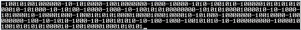
From this it can be seen that the length between ±1 and ±1 vary from 1 zero up to 9 zeros. In all there are 318 digits {0, ± 1} with the following distribution: 220 zeros, 58 ones and 40 minus one.
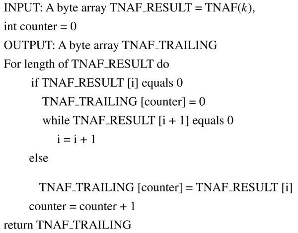
Removing the trailing zeros will make it practically impossible to recover the original sequence.
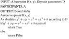
Now the following algorithm can be applied:
Algorithm 1: Removing trailing zeros
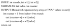
It must be clear that the point Q on the elliptic curve must be validated before it is used. The domain parameters are public and well-known by the participants and thereby the specific curve type is known. The validation can be done by verifying that a point Q ≠ 8 and also verifying that the point Q is on the curve by calculating for instance:
Algorithm 2: Validation of the ECC point
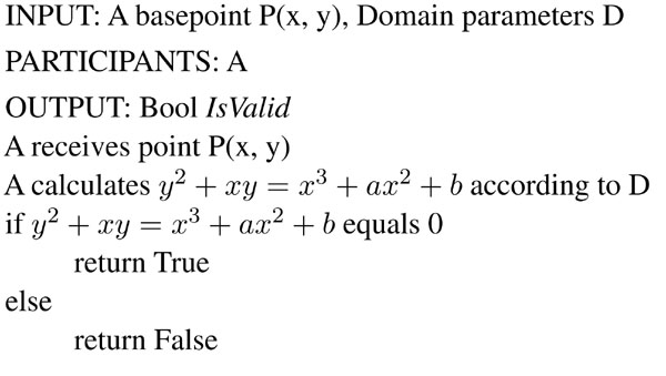
If the value False is received, a new base point must be chosen or a new calculation of point P(x, y) must be performed.
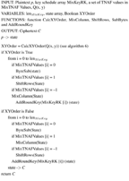
3.2. TNAF-based Key Schedule for AES
The dynamic TNAF-based key schedule for AES uses both the x and y coordinate of the common share Q(x, y). First the trailing zeros are removed from the TNAF values of Q(x, y) (algorithm 1) and the curve is validated (algorithm 2). The creation of round keys is depending on TNAF value of the x coordinate and the TNAF value of the y coordinate. Next issue is to place the keys for key schedule in a common array which is done as follows:
Algorithm 3: TNAF-based key schedule for AES
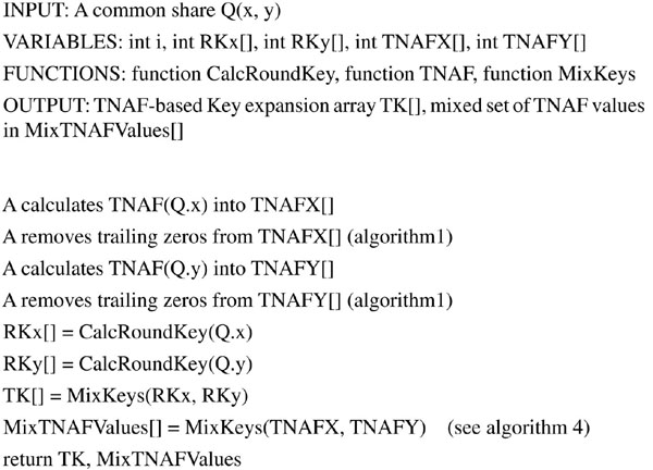
The general TNAF algorithm guarantees that 2/3 of the TNAF values are zeros. As explained above, in order to prevent new side-channels attacks trailing zeros are removed from the TNAF sequence of Q(x, y). In this way the key schedule is strengthened and the side-channel attacks and biclique attacks mentioned above will be avoided.
The MixKeys function algorithm looks like this:
Algorithm 4: MixKeys function of mixing round keys based on Q(x, y) or the Q(x, y) based TNAF values

In the case of mixing the expansion keys the output is placed in a new reordered array MixKeyRK and in the case of mixing the TNAF values, the output is placed in another reordered array MixTNAFValues.
Now that the sequence of keys has been placed in the array MixKeyRK, more flexibility can be added: It can be decided in the setup if the order in MixKeyRK should be from start or reverse. It can even be decided if the order is jumping after another pattern. The number of rounds is still supposed to follow the original number: For the 128 bits AES the number of rounds is 10, for the 192 bits AES the number of rounds are 12 and for the 256 bits AES the number of rounds are 14. The same flexibility can be added in case of MixTNAF Values.
3.3. TNAF-based Main Algorithm for Encryption and Decryption
The AES main algorithm can be further strengthen with a runtime decided mix of AES operations. In this way attacks as SPA (Simple Power Analysis) can be much harder to perform.
Since the ordinary AES is a simple combination of permutation and substitution the strength of the AES algorithm relies on the basic security of the mix of AES operations not the order of operation execution.
The TNAF sequences of the keys x and y created for the key schedule above is now used for the algorithm for encryption and decryption. The TNAF value decides at runtime the mix of the execution of the MixColumn, ShiftRows, SubBytes and AddRoundKey operations. Here follows the TNAF-based main encryption and decryption algorithm:
Algorithm 5: TNAF-based main encryption algorithm for AES
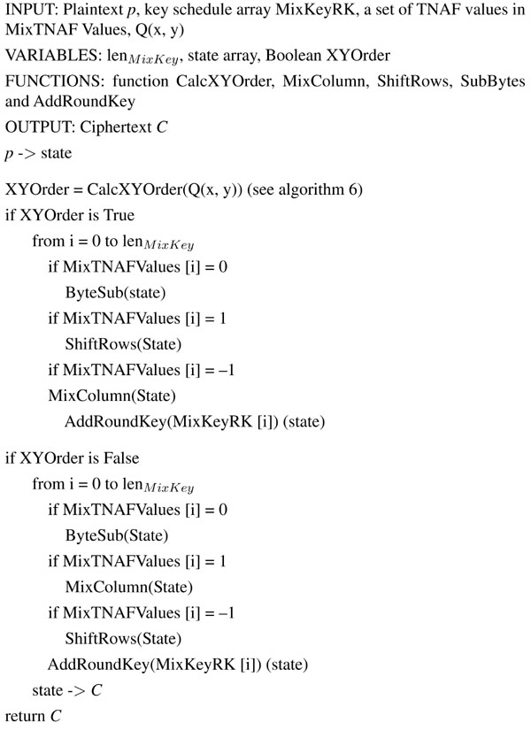
In the case of 128 bits AES LenMixKey should have the size 30 (3 × 10).
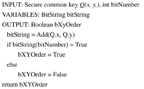
Because the private key is based on the common share Q(x, y) another security feature could be added to blur the calculation: A simple method to reverse the encryption and decryption order decided at run-time can be added:
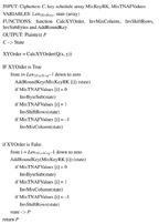
Algorithm 6: Run-time decided (x, y) order CalcXYOrder
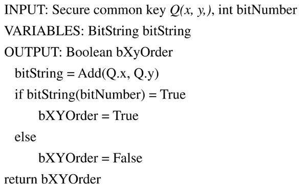
From this it can be seen that the order of the key schedule calculation of Q.x and Q.y can vary dynamically with the subtraction (binary addition) of Q.x and Q.y and afterwards test a bit in the resulting bit string.
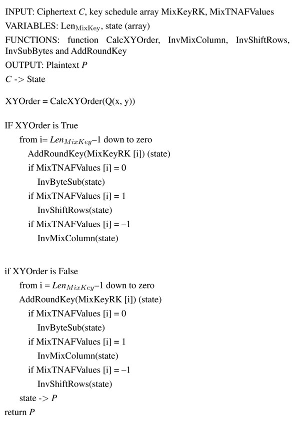
Now we define the decryption algorithm:
Algorithm 7: TNAF-based main decryption algorithm for AES
4. Implementation
The algorithms have been implemented in C++. The software contains implementation of a Koblitz ECC with TNAF and a standard AES implementation regarding the basic functions (AddRoundKey, MixColumn, ShiftRows, ByteSub plus the inverse functions).
The ECC implementation is divided into three layers: A basic layer, a field layer and an ECC main algorithm layer. The implementation is on the basic layer using a BitString struct. The ECC part has been tested against the main formula (4).
The TNAF algorithm is implemented the following way [8, p.117]:
Algorithm 8: TNAF algorithm
5. Tests and Results
Bob wants to send a message to Alice: “DYNAMIC AES”. In order to send this secret message initially a normal Diffie-Hellman key exchange is performed between the two participants Bob and Alice.
First a base point Q (163 bits) is chosen:
X: 5c94eee8 de4e6d5e aa07d793 7bbc11ac fe13c053 2
Y: ccdaa3d9 0536d538 321f2e80 5d38ff58 89070fb0 2
The two participants Bob and Alice have each a private key:
Bob: 3456abcd 50567367 ab568676 67556316 000000aa 00000001
Alice: fe562343 00567766 ab568863 34556668 23673ab7 00000002
Having the base point Q Bob and Alice calculate a common (secret) share C using the Diffie-Hellmann algorithm:
X: f1cc692c 86527792 31d37422 cb346bdf fc76aef0 00000000
Y: beea1cf7 b59ff099 28852977 e726d75d b06beab5 00000003
The common secret share is then tested (algorithm 1) to be on the curve by placing it into the equation (4). This ends the normal Diffie-Hellman key exchange. The output K(x, y) is now used as the symmetric key in AES.
The original AES algorithm uses a 4 × 4 byte state array as internal working array. Therefore one block of data to be encrypted or decrypted is of the size of 16 bytes. This array is reused in the TNAF based algorithm.
In the proposed TNAF based encryption algorithm the internal working process is:
- Places the plaintext bytes in the state array
- Perform key expansion of the private key (common share) (K.x and K.y)
- Calculates TNAF values of the private key (common share) (K.x and K.y)
- Removes trailing zeros from the TNAF sequences
- Perform the MixKeys functions
- Calculates the XY Order
- According to the TNAF values from the MixKey function (reordered TNAF values) runs through SubBytes, MixColumn, ShiftRows and AddRoundKey functions
The key expansion is reused from the original AES algorithm. Example on calculating the TNAF values (before removing trailing zeros): From the common secret share the TNAF values and the number of values in K.x and K.y. An example of the distribution {0, ±1}can be seen in Table 1.
Table 1 TNAF values
Using the MixKey function the TNAF values from K.x and K.y are combined into one sequence of TNAF values with trailing zeros removed from TNAF (K.x) and TNAF (K.y).
In order to obtain the same minimum of function call (call to SubBytes, MixColumn, ShiftRows and AddRoundKey) as in the original AES algorithm, the number of calls for a 192 bit key is set to 44.
The XYOrder is in this case true. From this follows that the sequence is as follows:
- SubBytes(state)
- ShiftRows(state)
- MixColumns(state)
- AddRoundKey(state, key_schedule);
The output ciphertext is:
0x 59 92 63 21 C2 8A C1 5A DD FE C7 52 77 B3 0D 54
The decryption algorithm is still performing the key expansion and the MixKey function. Also the XYOrder function is called to decide the order. The decryption algorithm uses the original InverseSubBytes, InverseMixColumn and the InverseShiftRows functions from the original AES algorithm. The TNAF values are run through in reverse order. The functions above are called in the same order as in encryption. The AddRoundKey function is called first, so the calling sequence is as here:
- AddRoundKey(state, RK [index]);
- InverseSubBytes(state)
- InverseShiftRows(state)
- InverseMixColumns(state)
The output plaintext is “DYNAMIC AES”.
5.1. Test Setup
In order to test the Dynamic AES a full implementation of ECC and Dynamic AES have setup. To give more precise time consumption for the specific parts of Dynamic AES the algorithms have been run through 10000 times each.
To avoid any caching in memory, the encryption algorithm has encrypted random generated data for each encryption block.
The dynamic AES will result in the same number of rounds as in the original AES in the main algorithm.
The TNAF-based AES along with ECC has been tested on an Intel(R) CoreTM2 Duo CPU @ 2.4 GHz.
5.2. Time Consumption Measurements
The proposed key scheduling mechanism is more time consuming, since two keys have to be scheduled and mixed combined with a calculation of two sets of TNAF values and a mix of keys. The time used for key scheduling has been measured in the implementation and the result is compared to the basic key scheduling function in standard AES as it can be seen in Table 2.
Table 2 Time Consumption Key Scheduling Mecahnism
The proposed Dynamic TNAF-based AES is using the same basic operations as the original AES in the main algorithm.
The main algorithm has been tested against a standard AES implementation. Table 3 shows the time consumption results of encryption and decryption algorithms for Dynamic AES and standard AES.
Table 3 Time Consumption Encryption / Decryption
We will now consider the expected throughput over a network using the values in tables 2 and 3. We assume that we want to transfer a file of 10 Mb data:
10 Mb = 10,240,000 bytes = 81,920,000 bits
The encryption and decryption time plus key schedule is calculated for a block of 16 bytes. The encryption operations can be done in 45.4501 sec and the decryption operations can be done in 46.901 sec. This means that the encryption flow is 1,802,416 bps and the decryption flow is 1,746,658 bps.
6. Analysis of Results
Not surprisingly, the proposed key schedule algorithm, as it can be seen from Table 2, is significantly more time consumable than the original key scheduling algorithm of AES. However, normally this algorithm is only executed once per session. The reason for this overhead is first of all the calculation of TNAF values. Second, the trailing of zeros and third, the extended calculation of round keys which uses more time compared to the original AES key schedule operation. Also the last operations, the MixKey operation and calculation of the (x, y) order, will consume more time compared to the original algorithm.
The encryption and decryption algorithms are also more time consumable as it can be seen in Table 3, even though the original AES standard operations are used. This is caused by the additional logic to decide which standard AES operation is going to be performed at runtime. A future run-time optimization of the Dynamic AES main loop instruction sequence is expected to remove this problem.
When considering the transfer of a 10 Mb file over network using a Dynamic AES session, the peak performance is expected to be limited more by the network than by the algorithm for instance when considering HTTPS (and Dynamic AES extended version hereof) over the Internet. As mentioned, the Dynamic AES is well suited to be together with at public key system as for instance elliptic curve cryptography. As it can be seen above the network traffic time is not part of the test. If the network traffic time was included, the time consumption difference between the standard AES and the Dynamic AES would even be less important.
7. Conlusions and Discussions
The proposed Dynamic AES approach is based on the TNAF function used in Koblitz curves in ECC. It will solve the problem of side-channel attacks, related sub-key attacks and biclique attacks on AES. The proposed AES algorithm is adding a dynamic approach to the key schedule mechanism and the main algorithm of the original AES. The key scheduling algorithm of the original AES algorithm has been improved with the combined use of ECC. Any side-channel attack based on the use of TNAF algorithm is removed by removing trailing zeros. The private key is now longer and the linearity has been removed since two private keys belonging to the ECC algorithm can be mixed. The main algorithm of AES has been improved by adding dynamic behavior instead of a static run through. With this enhancement, the content of the state array in AES becomes unpredictable.
The TNAF-based Dynamic AES has been implemented in C++ along with ECDH based on Koblitz curves. The new algorithm will differ slightly in processing time primarily because the original AES key schedule is changed but also the additions in the main algorithm will have a minor cost in terms of performance.
In the future we will look into run-time code optimization of the Dynamic AES.
8. References
[1] FIPS Pub 197, NIST, November 26, 2001
[2] Jaon Daemen, Vincent Rijmen, The Rijndael Block Cipher, csrc.nist.gov, Sep. 1999
[3] Joseph Bonneau, Side-Channel Cryptoanalysis (Research students' Lectures), University of Cambridge Computer Laboratory, May 4, 2010.
[4] Dag Arne Osvik, Adi Shamir and Eran Tromer, Cache Attacks and Countermeasures: the Case of AES, osvik.no / Department of Computer Science and Applied Mathematics, Weizmann Institute of Science, Rehovot 76100, Israel, 2005
[5] Joseph Bonneau and Ilya Mironov, Cache-Collision Timing Attacks Against AES, Computer Science Department, Stanford University and Microsoft Research, Silicon Valley Campus, 2006
[6] Alex Biryukow and Dmitry Khovratowich. Related-Key Cryptanalysis of the Full AES-192 and AES-256, p.1-18, ASIACRYPT 2009
[7] Andrey Bogdanov, Dmitry Khovratovich, and Christian Rechberger, K.U. Leuven, Belgium; Microsoft Research Redmond, USA; ENS Paris and Chaire France Telecom, France, Biclique Cryptanalysis of the full AES, ASIACRYPT'11, August 31, 2011
[8] Hankerson, Menezes and Vanstone, “Guide to Elliptic Curve Cryptography”, Springer, 2004.
[9] Henrik Tange, Birger Andersen, Secure Plain Diffie-Hellman algorithm, Journal of Cyber Security and Mobility, 2012
[10] Felipe Ghellar, Marcelo Soares Lubaszewski, A Novel AES Crypotographic Core Highly Resistant to Differential Power Analysis Attcks, Jorunal Integrated Circuits and Systems, 2009
[11] Stefan Tillich, Johann Groβschädl, Power Analysis Resistent AES Implementation with Instruction Set Extensions, LNCS 4727, 2007
[12] Lingguo Cui, Yuanda Cao, A New S-Box Structure Named Affine-Power-Affine, ICIC International, 2007
Biographies

Henrik Tange received the B.Eng (export engineer) from the Copenhagen University College of Engineering in 1999 and the M.Sc. in Communication Network specializing in Security from Aalborg University in 2009. Since 2009 he has been a PhD student at Aalborg University. Since 2000 he has been teaching at Copenhagen University College of Engineering which merged into Technical University of Denmark.

Birger Andersen is a professor at Technical University of Denmark, Copenhagen, Denmark, and director of Center for Wireless Systems and Applications (CWSA). He received his M.Sc. in computer science in 1988 from University of Copenhagen, Denmark, and his Ph.D. in computer science in 1992 from University of Copenhagen. He was an assistant professor at University of Copenhagen, a visiting professor at Universität Kaiserslautern, Germany, and an associate professor at Aalborg University. Later he joined the IT department of Copenhagen Business School, Denmark, and finally Copenhagen University College of Engineering which merged into Technical University of Denmark. He is currently involved in research in wireless systems with a focus at security