Adaptive Matrix Pattern Steganography on RGB Images
Amirfarhad Nilizadeh1,*, Shirin Nilizadeh2, Wojciech Mazurczyk, Cliff Zou and Gary T. Leavens
1University of Central Florida, Orlando, Florida, USA
2University of Texas Dallas, Dallas, Texas, USA
3Warsaw University of Technology, Warsaw, Poland
E-mail: af.nilizadeh@Knights.ucf.edu
*Corresponding Author
Received 25 May 2021; Accepted 28 June 2021; Publication 13 August 2021
Abstract
Almost all spatial domain image steganography methods rely on modifying the Least Significant Bits (LSB) of each pixel to minimize the visual distortions. However, these methods are susceptible to LSB blind attacks and quantitative steganalyses.
This paper presents an adaptive spatial domain image steganography algorithm for hiding digital media based on matrix patterns, named “Adaptive Matrix Pattern” (AMP). The AMP method increases the security of the steganography scheme of largely hidden messages since it adaptively generates a unique codebook matrix pattern for each ASCII character in each image block. Therefore, each ASCII character gets a different codebook matrix pattern even in different regions of the same image. Moreover, it uses a preprocessing algorithm to identify the most suitable image blocks for hiding purposes. The resulting stego-images are robust against LSB blind attacks since the middle bits of green and blue channels generate matrix patterns and hiding secrets, respectively. Experimental results show that AMP is robust against quantitative steganalyses. Additionally, the quality of stego-images, based on the peak signal-to-noise ratio metric, remains high in both stego-RGB-image and in the stego-blue-channel. Finally, the AMP method provides a high hiding capacity, up to 1.33 bits per pixel.
Keywords: Steganography, Steganalysis, LSB, Matrix Pattern.
1 Introduction
Digital image steganography is one of the most popular techniques for hiding a secret message in an image [26, 36, 71]. Images have a high capacity, which is enough for steganographic purposes; also, images are currently widely used, e.g., in social media networks. Data hiding techniques in images can be classified into three main groups: spatial domain, transform domain, and adaptive steganography [5]. Spatial domain steganography hides a secret message by changing pixel values [26], classic algorithms in the spatial domain are Least Significant Bits (LSB) [4, 27], LSB Matching (LSBM) [47], Pixel-Value Differencing (PVD) [80], Exploiting Modification Direction (EMD) [82], and Synch [8]. Transform domain steganography systems hide the message by changing the frequency coefficients of images [65], such as JSteg [67], YASS [70], Uniform Embedding Distortion (UED) [20], and J-UNIWARD [24] that are classic algorithms in the transform domain. Finally, adaptive steganography algorithms hide the message in either the spatial or transform domains. These algorithms have a pre-processing phase (such as STC coding method [14]) that can choose the most suitable area of the image for hiding a secret message with minimum changes [18, 68] like Edge Adaptive (EA) [41], HUGO [61], Wavelet Obtained Weights (WOW) [23], High-pass, Low-pass, and Low-pass (HILL) [37], J2-UNIWARD [9] and Natural Steganography (NS) [7].
Almost all the spatial domain image steganography methods change the LSB part of pixels [1, 16, 48, 11, 4] because human eyes are not sensitive to these changes. However, they are sensitive to unintentional processes such as randomly flipped bits, image filters, and image compression algorithms [6, 39]. The LSB blind attacks use this sensitivity because only flipping one bit in the LSB part of a pixel can destroy the entire hidden message. These attacks are completely blind, and they consider any image as a potential stego-image and try to destroy the secret message.
Steganalysis algorithms are another kind of attack to detect the existence of a hidden message in a stego-image [28, 66]. Many of these algorithms have no information about the steganography algorithm’s specification and are known as blind steganalysis [3, 19, 42]. Also, quantitative steganalysis algorithms try to detect the existence and estimate the hidden message’s length in the stego-image [62]. Many blind and quantitative steganalysis algorithms have been developed to detect the existence of a hidden message in a stego-image [10, 12, 13, 17, 31, 33, 43, 50, 60, 64, 75, 79].
This paper proposes a steganography method that hides information in the middle bits of images instead of the image’s LSB part. This can affect the stego-image quality. To limit this impact, we present a novel adaptive multimedia spatial domain steganography algorithm based on matrix patterns called “Adaptive Matrix Pattern” (AMP). We show that our proposed steganography method is resistant to LSB blind attacks and steganalysis algorithms, maintains the quality of stego-image, and has a high capacity.
In this work, an RGB image is considered to have three channels, each represented with pixels. Also, each pixel is an 8-bit non-negative integer. An AMP algorithm modifies one channel’s pixels (typically the blue channel because the human eye is less sensitive to differences in this channel) by a matrix pattern, which is adaptively generated from the cover image’s texture. We propose dividing an RGB image into non-overlapping square-sized blocks, and ordering them based on their suitability for hiding messages, considering the smoothness and complexity of neighboring pixels. For each block, a codebook consisting of 257 unique dynamically-sized matrix patterns is generated, representing 256 ASCII codes and an end of message character, which increases the hidden message’s security. In other words, each character gets a different codebook matrix pattern even in different regions of the same image. This method enables hiding any digital media in the image, such as text, voice, video, encrypted data, etc. The and bits of each block’s green and blue channels are used for generating matrix patterns and hiding a secret message. Using these bits instead of LSB bits increases our steganography algorithm’s robustness against LSB blind attacks and well-known blind and quantitative steganalysis. Also, our experimental results show that the AMP steganography method provides high transparency for stego-images.
Considering the above, the contributions of this paper are as follows:
1. This work supports all 256 ASCII characters, while the earlier MP works [49, 54, 51, 83] supported only 49 and 95 English keyboard characters. Thus, any digital media can be hidden as a message like a cryptographically encoded message. (A steganography work is practical when it can hide encrypted messages to increase security.) Also, the proposed AMP method provides a large capacity for hiding information as it uses six pixels (in the blue channel) to hide each byte.
2. Our proposed algorithm is adaptive in the spatial domain. A pre-processing algorithm identifies the suitable blocks for hiding, considering the smoothness and complexity of neighboring pixels in each block. Some blocks cannot hide information, while others can hide more information. Also, some blocks with different textures need fewer changes to hide the same message; such blocks receive a higher priority.
3. This is the first time that a Matrix Pattern (MP) steganography algorithm has been evaluated on a large image dataset; we used 10,000 images from BOSSBase [59] (instead of 13 images in earlier MP studies [49, 54, 55, 51, 83]). Results show that our proposed AMP method is robust against well-known quantitative steganalysis methods while maintaining the quality of stego-images in both stego-RGB-image and stego-blue-channel.
The source code of this research is available on a GitHub repository [53].
2 Related Work
The most closely related work is spatial domain steganography algorithms because they hide secret messages by changing pixel values and handling large messages (unlike algorithms that use the transform domain). Related spatial algorithms also divide cover images into non-overlapping blocks to detect noisy blocks in which hidden data will be less detectable by steganalysis methods.
Almost all existing steganography works based on blocks use the least significant bits (LSB) part of each pixel and thus are vulnerable to blind LSB attacks and quantitative steganalysis algorithms. For example, Hsiao’s “Block-based reversible data embedding” [25] divides an image into blocks, which are then classified into one of three classes: smooth, normal, and complex. Then, it uses the LSB portion of each pixel for hiding a secret message. Also, a recent work [69] uses the knight’s tour to hide the message in the image’s blocks by modifying LSB. Pixel Value Ordering (PVO) [38] is another work that uses prediction error expansion in each non-overlapping block in the hiding process. Many works use the PVO algorithm [44, 78, 58]. Also, a work presented by Weng et al. [77] divides images into non-overlapping blocks; their proposed work at most can hide 2 bits by using 3 pixels. Another example is Kawaguchi’s “Bit-Plane Complexity Segmentation Steganography” (BPCS) [30]. In BPCS, a secret message is changed into some noisy blocks; then, they are embedded into the cover image by replacing other suitably noisy cover blocks (LSB part of pixels in the block). Another method similar to BPCS is “A Block Complexity based Data Embedding” (ABCDE) by Hoki [21]. In another work [40], the secret message is hidden in the noisy blocks of an image, where the LSBM method is applied on each block [47]. Also, PVD [80] divides an image into non-overlapping blocks of two consecutive pixels. In the PVD method, a secret message is mostly hidden in the noisy blocks compared to the smooth blocks. Many steganography works are based on the PVD algorithm [29, 46, 56, 72, 81].
It is also worth noting that the above-mentioned algorithms are only defined for gray-scale images, not RGB images like the AMP method proposed in this paper. Also, some related works are using RGB images for hiding secret messages, like the work presented by Pervez and Gutub [57] that uses one of the channels as an indicator and the two remaining channels for hiding the message. It is assumed that a shared key and a partition scheme are agreed upon between the sender and the receiver in their work. Some other steganography works (like [45, 73]) improve their technique and use the same indicator idea.
All of the above steganography techniques (both block-based and RGB works) make changes in the LSB part of an image with different embedding algorithms. Thus, a simple LSB attack would destroy the hidden message.
Lastly, this paper is based on matrix pattern (MP) steganography [51]. That work selects non-overlapping square-sized blocks based on a pseudorandom generator, and it supports only 49 matrix patterns (English characters) instead of 257 matrix patterns (ASCII characters) by our proposed AMP work. Moreover, in [51] the to bits of the image are used for generating and hiding matrix patterns. Another work based on the MP method [55] uses both MP and LSB algorithms to hide a secret message. The other prior work [54] is a block-based spatial steganography version of MP, in which blocks are selected randomly, and 95 codebook matrix patterns are generated from each block to assign all English keyboard characters. The present AMP algorithm builds upon these works but with fewer limitations. Another work based on the MP method is presented by Zhou et al. [83], which combines the MP method (which supports 95 characters) with PVD [80] to increase the capacity. Also, Mowafi et al. [49] presented a paper based on MP, but instead of using RGB channels, they use YCbCr color space. In their work, they used the MP version that supported 95 characters. All the above MP works used small image datasets (13 images) for their evaluation. Also, earlier MP works only could hide text messages in an image. However, in the real world, a steganography framework should hide encrypted messages to increase security. Furthermore, they used random and pseudorandom generators, while pre-processing is used in our work to select the most suitable blocks, which enhances the information-carrying capacity of the algorithm while providing high stego-image quality.
3 The Proposed Method
In this section, a new adaptive steganography algorithm based on the matrix pattern is proposed. The AMP steganography method does not encode individual bits; instead, it encodes each character (byte). It divides an image into non-overlapping square-sized blocks. Then, it automatically generates unique matrix patterns from the block texture and assigns each to an ASCII character. Each block in the image has its unique codebook matrix pattern based on the block’s texture. There is one matrix pattern for each of the 256 ASCII characters plus one matrix pattern for the end-of-message. Thus, all kinds of digital media can be considered a stream of characters (bytes) as a secret message and then hidden in the cover image. The algorithms for matrix pattern generation and embedding are the same as algorithms used in our prior MP work [54]. However, selecting suitable blocks to generate 257 unique matrix patterns from the block’s texture and provide a high-quality stego-image is one of the challenges. Thus, the proposed AMP work uses a pre-processing algorithm instead of random or pseudorandom algorithms to select the most suitable blocks.
3.1 Pre-Processing Analysis
Selecting the most suitable image region to hide secret messages will increase the quality of the stego-image, which makes the steganography method more secure. In the MP method, selecting the most suitable blocks is more critical because a codebook of matrix patterns will be generated based on the block’s texture. The codebook will be used to hide the secret message in the same block. In this paper, instead of using pseudorandom or random algorithms (as in previous work on MP), we use a pre-processing algorithm for detecting the most suitable blocks to generate a codebook matrix pattern and hide a secret message with minimum changes, which will increase the message’s secrecy.
In the “Block Texture Pattern Detection” paper [52], the gray-scale blocks are divided into four different classes: edge and simple, edge and complex, smooth and simple and smooth and complex. The capacity and transparency of three different steganography methods containing LSB, PVD, and MP are evaluated in each class. Smoothness and complexity are two measures used in that prior work [52], and they will be discussed next alongside the effects of this classification on the MP method.
In [52], the user selects a fixed size, , for the blocks, which use in the MP method to generate codebook and hiding secret messages. Then, all the blocks are changed from RGB to intensity blocks using Equation (1), which defines the intensity of each pixel .
| (1) |
After that, the variance of the pixels’ intensities in a block is computed as a measure of the degree of smoothness shown with Equation (2).
| (2) |
A straightforward algorithm is used to compute the complexity of a block. First, the average of the pixels in the intensity block is calculated. Next, the gray-scale block (intensity block) is changed to a binary block by changing all pixels with an intensity at least as large as the average to white and all others to black. All the black to white and white to black changes are counted in horizontal, vertical, and diagonal orders. Finally, to normalize the complexity measure, the total number of changes in these directions is divided by the maximum number of possible block changes. The complexity is calculated with Equation (3).
| (3) |
In this equation, “” determines the size of a block, and “” is the number of total changes in all horizontal, vertical, and diagonal orders in a given block, .
The prior work [52] shows that the “smooth and complex” blocks provide the highest MP method capacity. Also, “smooth and complex” blocks have better transparency than “edge and simple” and “edge and complex.” Also, “smooth and simple” blocks are not suitable for embedding information. Furthermore, the evaluation presented indicates that “edge and complex” has nearly 10% better capacity than “edge and simple.” These results highlight some important facts related to the MP method: imagine a uniform block, where all the pixels are the same. In this block, it is impossible to generate different matrix patterns because their generation is based on subtraction and the difference between neighboring pixels. If all the pixels are the same, it will generate a matrix pattern with zero values. Thus, if a block is entirely “smooth and simple”, it is impractical to generate enough unique matrix patterns for the block. One of the AMP method’s challenges is detecting suitable blocks that can generate 257 matrix patterns to support all ASCII characters.
By comparing “edge and complex” and “smooth and complex” blocks, which have the same factor in “complexity”, “smooth and complex” has a better capacity. This is because in the edge areas, but not in smooth areas, the difference in two pixels’ values while generating a matrix pattern can be higher. Also, in the edge area, the values of matrix patterns are higher. Thus, it is more probable that pixel overflow happens during the embedding phase by adding matrix patterns to the blue channels’ values. In this case, the null matrix is embedded, and it will decrease the transparency, while no character is hidden there. Consequently, “edge and complex” and “edge and simple” areas have less capacity than “smooth and complex” areas.
In this paper, blocks are ordered based on these four classes. The “smooth and complex” blocks are the most suitable, followed by “edge and complex”, “edge and simple,” and finally “smooth and simple” ones.
3.2 Matrix Pattern Generation
In AMP, the user selects two fixed sizes, a number of pixels, , that determines the block size, , and sizes for the matrix patterns, also in pixels, and , the matrix patterns size are . Also, the user provides a cover RGB image and a secret message. Some requirements that the user must consider for selecting block and matrix pattern sizes are: , , and the number of characters supported (257) must be less than .
After selecting one block, the algorithm selects the first top left matrix in the green channel and uses that to generate the first matrix pattern for the block. We use to denote this matrix.
In the matrix pattern generation process, each pixel’s first three bits in the green channel are ignored (by considering them zero) because they are used in blind LSB attacks. After that, the first row (top row) of the matrix pattern is made to be zero and, the second row of the green matrix-cover is subtracted from the first row of the green matrix-cover to produce the second row of the matrix pattern. This continues until the algorithm computes the value of the cover’s row minus the value of row of the green matrix-cover, which generates the row (bottom row) of the matrix pattern. Equation (4) explains how a matrix pattern is generated.
| (4) |
We write for the matrix pattern created by Equation (4). To generate the second matrix pattern, for the second (ASCII) character, the top left matrix (used for generating the first matrix pattern) in the green channel will be shifted one column to the right. The same process shown in Equation (4) will then generate the second matrix pattern. The process of shifting one column and generating a new matrix pattern continues until enough unique matrix patterns (257) are generated, or the process reaches the end of the block’s row (by one column shifting each time). If it reaches the end of the row, it shifts one row down and starts again from the leftmost column of the block, until all 256 ASCII characters and the “end of message” character get a unique matrix pattern. A generated matrix pattern that is not unique for the block and assigned to an ASCII character in the block codebook earlier will be ignored.
In this work, the and bits are used to generate matrix patterns based on our prior work [54]. Therefore, if there is at least one value higher than 24 or lower than -24 in the generated matrix pattern, it will be ignored1. In matrix pattern generation, if 257 unique matrix patterns cannot be generated from a block to assign all 256 ASCII characters and the end-of-message character, then that block will be considered a useless block. Thus, no character can be hidden in the block.
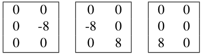
The left matrix in Table 1 shows an example of pixel values of a green channel. The right matrix in this figure shows pixel values after ignoring the first three bits. Also, Table 2 shows three matrix patterns generated based on the matrix in the figure 1. The first two columns of the right matrix of the Table 1 are used to generate the first matrix pattern shown in the left matrix in Table 2. Then, the second and third columns in Table 1 (after one column shifting) are used to generate the second matrix pattern shown in the middle matrix of Table 2. The third and fourth columns in Table 1 are used to generate the second matrix pattern shown in the right matrix of Table 2.
Table 1 Left Matrix: Values of a green channel; Right Matrix: The green channel with the ignored first three LSB bits
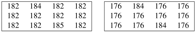 |
Table 2 Three generated matrix patterns
 |
3.3 Embedding Phase
In the AMP method, the blue channel of a block is used in the embedding process. In this phase, the matrix pattern assigned to the secret message’s first character is selected from the block’s codebook matrix pattern. In the embedding phase, the first top left matrix of the blue channel of the block will be chosen; the notation indicates this matrix.
To embed the matrix pattern into the (that will produce the stego-matrix), no changes will be made on the first row (top row) of the blue matrix. Then, values of the first row of the stego-matrix are added to the values of the second row of the matrix pattern to produce the values of the second row of the stego-matrix. This process will continue until row (bottom row) of the stego-matrix is produced; by adding row of the stego-matrix to row of the matrix pattern. This process is described by Equation (5). In this equation, the is embedded in the block .
| (5) |
We write for the the stego-matrix in the blue channel.
For embedding the secret message’s second character into the block, the second matrix of the blue channel of the block will be selected (by shifting columns to the right of the block location, which was used to embed the first matrix pattern). Then, the matrix pattern, which is assigned to the second secret message character, will be embedded using Equation (5). The process of shifting and embedding will continue until it reaches the end of the block’s row. Then, it will shift rows down, and it will move to the leftmost matrix in the new row. This process will continue to embed all the secret message characters, and if the space of the block is not enough, the process will continue with the next block using a new matrix pattern codebook. Lastly, when the entire secret message is embedded in the blocks, the matrix pattern assigned to the end-of-message character will be embedded.
Pixel overflow can happen during the embedding of a matrix pattern. In this case, a null matrix pattern with all zero values is embedded instead of the matrix pattern. The null matrix pattern is a pre-defined matrix pattern for all of the blocks, and it is not included in the 257 matrix patterns generated during the matrix pattern generation phase. The null matrix pattern does not make values of pixels in the stego-image zero; only values of matrix pattern are zero, and it will be embedded as explained in Equation 5 like other matrix patterns.
During the embedding process, the sizes of blocks () and the matrix pattern ( and ), and the order of blocks from the most to least suitable one are embedded with the same process. These values are embedded in the top left block(s) with matrix pattern sizes. All of the information embedded in this specific block(s) are numerical digits. Thus, 12 unique codebook matrix patterns are generated for these blocks. Ten of them are assigned to numerical digits, one matrix pattern is assigned to a space character for separating values, and one is assigned to the end-of-message character.
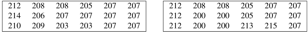
The left matrix of Table 3 shows pixel values of the cover blue channel. The right matrix of Table 3 is a stego-matrix that embeds the three generated matrix patterns shown in Table 2. The left matrix pattern in Table 2 is embedded in the first pixels values of the right matrix of Table 3 (first and second left columns). Also, the middle and right matrix patterns of Table 2 are embedded in the second pixels values (third and fourth columns) and third pixels values (fifth and sixth columns) of the right matrix of Table 3.
Table 3 Left Matrix: Pixel values of a cover blue channel; Right Matrix: Pixel values after embedding three matrix patterns
 |
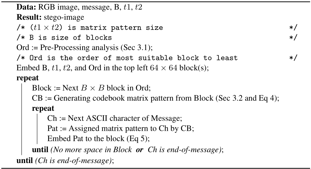
Algorithm 1 shows the embedding pseudocode based on the AMP algorithm at the sender side.
Algorithm 1: Embedding()
3.4 Extraction Phase
To extract the embedded secret message, first, the operation Ex extracts the size of both blocks and the matrix patterns (recovering and and ) and the order of the blocks’ locations; they are embedded in the top left block(s) of the image. Extracting these values is the same as the extraction phase (using Equation (6)), which is explained later in this section. After that, the extracted block locations (selected with the pre-processing algorithm) are placed in the queue order. Then, the codebook matrix pattern of the first block in the queue is generated using Equation (4), which is discussed in Section 3.2. The green channel does not change in the embedding phase. Thus, generated codebook matrix pattern on the receiver side is the same as the sender side.
The first matrix (stego-matrix) on the top left of the blue channel of the stego-block is selected to extract the first embedded matrix pattern. Recall the first row values (top row) of the matrix patterns are zeros. To extract the values of the second row of the embedded matrix pattern from the stego-matrix, the pixel values in the second row of stego-matrix (from the blue channel) will be subtracted from the first row of the stego-matrix. Then, to extract the third row of the embedded matrix pattern, the pixel values of the third row of the stego-matrix (from the blue channel) will be subtracted from the second row of the stego-matrix. This process continues until the subtraction of row from row extracts the values of row (bottom row) of the hidden matrix pattern. Equation (6) describes how the extraction of the matrix patterns is performed.
| (6) |
In Equation (6), “Ex” refers to the extracted matrix pattern, and “Em” is the stego-matrix, shown as . Also, the notation of indicates the extracted matrix pattern, which is the same as one of the matrix patterns in the block’s codebook. Then, to extract the second matrix pattern, the second stego-matrix in the block will be selected by shifting columns to the right from the first stego-matrix. This shifting and extracting process will continue until it reaches the end of the selected block column. Then, it will shift rows down, and it will start again from the leftmost matrix in the new row of the block. Each extracted matrix pattern from the blue channel is assigned to the ASCII character hidden in each matrix based on the block’s codebook. The null matrix pattern with all zero values is a pre-defined matrix pattern for all of the blocks. Extracting a null matrix pattern will show that no character (byte) is hidden in this matrix. All hidden characters (bytes) in the block are extracted by following the same process. Then, the same process will continue by selecting the next block in the queue until the end-of-message character is detected.
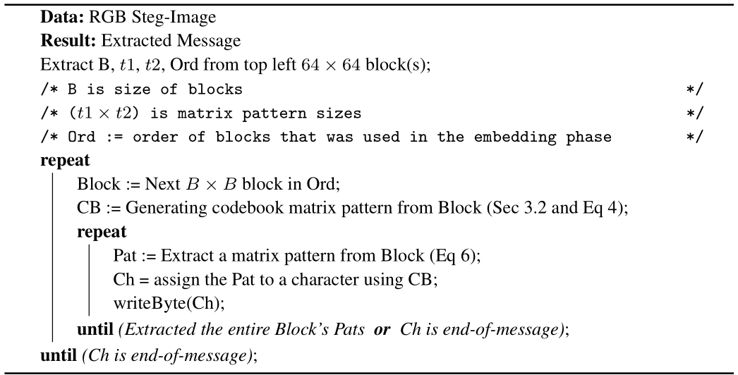
Algorithm 2 shows the pseudocode of extracting an embedded message from the RGB stego-image using AMP.
Algorithm 2: Extracting()
4 Implementation and Evaluation
This section includes details related to the inputs, outputs, limitations, and implementation of the proposed adaptive steganography method. We also characterize the dataset of 10,000 RGB images used during experiments. Finally, AMP’s resistance against well-known quantitative steganalysis is evaluated, and the quality of stego-images is measured using PSNR.
4.1 Implementation
We use MATLAB R2018a for the implementation and evaluation of the AMP algorithm. Inputs of the proposed method are a secret message and an arbitrary RGB cover image. Also, the sender selects a value for the size of the blocks () and two values ( and ) for the size of the matrix patterns. Then, the AMP method hides the secret message in the blue channel of the cover image as described earlier. As a result, at the output, we have an RGB stego-image (or a warning if not all of the message could be hidden in the cover image). At the receiver side, the input of the AMP algorithm is an RGB stego-image. For the receiver, the output is the secret message that is extracted from the stego-image.
The cover image can be in any format with three channels. However, the output can only be an image format with three channels that do not use lossy compressions, such as the PNG, Bitmap, TIFF, and PPM formats. Like all known spatial domain works, a lossy compression algorithm, such as JPEG or JPEG2000, cannot be used to transmit stego-images produced by the AMP algorithm.
The source code of an AMP implementation is available on a GitHub repository [53].
4.2 Images Dataset and Evaluation
The image dataset that was used in previous MP evaluations was small (13 images) [49, 54, 55, 51, 83]. In this paper, instead, we use the 10,000 images of the BOSSBase dataset [2]. The RAW RGB images of BOSSBase were resized and cropped to create a new dataset of 10,000 RGB images with size. UFRaw 0.22 was used for changing RAW images to the PPM image format with three channels. A script provided for the BOSS competition was used for resizing and cropping [2, 35]. Also, for the embedding process, a random secret message was generated each time, which has the characteristic of an encrypted message.
In our evaluation, the size of the matrix pattern was , and and bits were used for generating and embedding matrix patterns (previous works on the MP method showed that these are the most suitable size and bits [51, 54]). Thus, 6 pixels are used for hiding a byte in our study. Also, the block size was chosen as . In previous MP works, the block size was . However, AMP needs to generate 257 unique matrix patterns, and blocks of size cannot provide it. This paper did not evaluate the optimal block size; however, our initial evaluation showed that blocks with a size of have good results.
We created four different stego-image datasets from the same set of cover images, distinguishing the datasets based on each image’s percentage capacity used in the embedding process. The size of each blue channel during the experimental evaluation is , and the size of each matrix pattern is . Thus, the maximum number of possible ASCII characters (bytes) that can be hidden in an image is , which is 43,690 characters (349,520 bits)2. It shows that AMP provides a large capacity for hiding. Most of the spatial domain steganography works hide bits by replacing or using a correlation among neighboring pixels in the LSB parts. Thus, their hiding capacity is bits per pixel (bpp), and bpp is a known measure used in steganography research. However, this work uses every 6 pixels for hiding a byte (8 bits); it can increase the steganographic capacity up to 1.33 times more than simple LSB replacement, which its capacity is 1 bpp. In our first dataset, 5% of bpp is used for hiding in the blue channel. In the other three stego-image datasets, 10%, 20%, and 40% bpp of blue channel capacity is used for hiding random secret messages, respectively. Our results showed that some of the 10,000 images in the cover image dataset could not hide such messages. Recall from section 3.1 that, in some images, the texture of most of the blocks is “smooth and simple”, and the AMP algorithm cannot generate enough matrix patterns for them. Also, changing the and bits of pixels in “smooth and simple” blocks will decrease the quality of stego-image, which is one of the limitations of hiding in the middle bits instead of the LSB. In our 5, 10, 20, and 40 percentage stego-image datasets, we have 9430, 9202, 8746, and 7611 images, respectively. These four stego-image datasets and their cover image datasets are used to measure the quality of stego-images with PSNR and evaluate the resistance of the AMP algorithm against some well-known quantitative steganalysis works. Figure 1 shows three images from the BOSSBase dataset (images number 1, 10 and 100 in the dataset) and their stego-images. Left images are cover images, and the other four images contain 5%, 10%, 20%, and 40% bpp embedded messages from the left to the right.
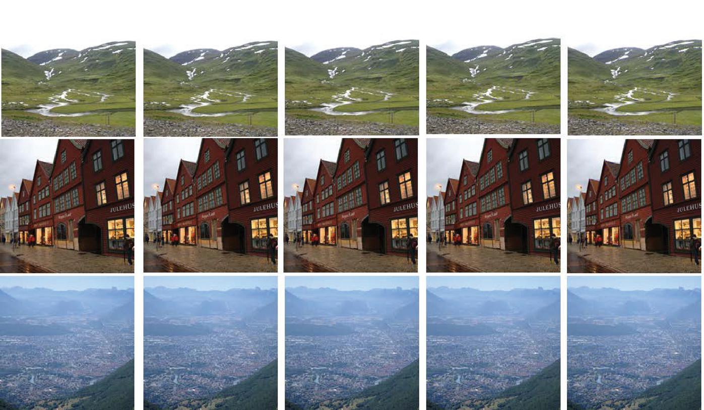
Figure 1 Left images are cover images, other four images contain 5%, 10%, 20% and 40% bpp embedded messages from left to right.
The quality of stego-images is evaluated with PSNR. Each pair of cover and its stego-image are used for computing PSNR. The RGB and blue channel of each pair is used for this evaluation. The Luminance signal (Equation 7) is used to compute the brightness of each RGB cover and its stego-image [22, 74]
| (7) |
Table 4 shows the average of PSNR results. The average of PSNR values for both RGB images and blue channels is much higher than 30dB. This shows that the quality of stego-images is kept after hiding a message [74, 76]. Results are rounded to four decimal places.
Table 4 PSNR Results (10,000 images)
| PSNR [dB] | 0.05 | 0.10 | 0.20 | 0.40 |
| RGB | 58.5307 | 55.4773 | 52.4981 | 49.5129 |
| Blue | 54.7529 | 51.6831 | 48.6934 | 45.6973 |
In the quantitative steganalysis evaluation three prior works are used: sample pairs (SP) [10, 34], triples analysis [31] and weighted-stego (WS) [32, 33]. We obtained the source code from Prof. Fridrich’s website with their initial values [15]. These quantitative steganalysis works estimate the length of a hidden message in an image [63]. In this experimental work, the blue channel of stego-images and their cover images are used for evaluation. Table 5 shows the result of the average estimation for these three quantitative steganalysis works. Results are rounded to four decimal places.
Table 5 Quantitative Steganalysis Results (10,000 images)
| Capacity (bpp) | SP | Triples | WS |
| Cover (5%) | 0.0131 | 0.0034 | 0.0014 |
| 0.05 | 0.0135 | 0.0037 | 0.0013 |
| Cover (10%) | 0.0130 | 0.0035 | 0.0013 |
| 0.10 | 0.0138 | 0.0041 | 0.0011 |
| Cover (20%) | 0.0134 | 0.0036 | 0.0013 |
| 0.20 | 0.0147 | 0.0045 | 0.0011 |
| Cover (40%) | 0.0141 | 0.0040 | 0.0013 |
| 0.40 | 0.0172 | 0.0061 | 0.0010 |
Table 5 shows that the average estimation of hidden message length for both stego-images and their cover images are similar. Also, the estimated average length of hidden message in stego-images are not correct. Thus, these steganlysis works are not successful against AMP.
To summarize, AMP is resistant against quantitative steganalysis works, and also it provides high transparency and high capacity for hiding a large digital secret message.
5 Conclusion
This paper describes an Adaptive Matrix Pattern (AMP) steganography algorithm for hiding digital media within the RGB image including cryptographically encrypted messages. This work increases security by generating a unique codebook matrix pattern for each region of an image. A pre-processing algorithm is used for ordering and selecting image blocks, which enhances the transparency and information-carrying capacity of the algorithm.
Experimental results using the BOSSBase dataset show that AMP is resistant to known quantitative steganalysis works and provides high-quality stego-images. Also, the first 3 LSB pixels are not used in the embedding process; thus, blind LSB attacks cannot destroy the hidden message.
Acknowledgement
Thanks to Dr. Fridrich, Dr. Cogranne, Dr. Pevny, and Dr. Holub for answering our emails and sharing scripts to transfer the RAW RGB images of the BOSSBase dataset to RGB images.
Notes
1Note that 24 is , so the restriction to the interval keeps the values in the and bits.
2The maximum possible capacity is lower, as a block(s) of the cover image is used for hiding the selected sizes and the order of blocks.
References
[1] Wassim Alexan, Ahmed Hamza, and Hana Medhat. An aes double–layer based message security scheme. In 2019 International Conference on Innovative Trends in Computer Engineering (ITCE), pages 86–91, Aswan, Egypt, 2019. IEEE.
[2] Patrick Bas, Tomáš Filler, and Tomáš Pevnỳ. ” break our steganographic system”: the ins and outs of organizing boss. In International workshop on information hiding, pages 59–70, Berlin, Heidelberg, 2011. Springer.
[3] Saman Shojae Chaeikar and Ali Ahmadi. Ensemble sw image steganalysis: A low dimension method for lsbr detection. Signal Processing: Image Communication, 70:233–245, 2019.
[4] Rajarathnam Chandramouli and Nasir Memon. Analysis of lsb based image steganography techniques. In Image Processing, 2001. Proceedings. 2001 International Conference on, volume 3, pages 1019–1022, Thessaloniki, Greece, 2001. IEEE.
[5] Abbas Cheddad, Joan Condell, Kevin Curran, and Paul Mc Kevitt. Digital image steganography: Survey and analysis of current methods. Signal processing, 90(3):727–752, 2010.
[6] Sheshang D Degadwala, Mohini Kulkarni, Dhairya Vyas, and Arpana Mahajan. Novel image watermarking approach against noise and rst attacks. Procedia Computer Science, 167:213–223, 2020.
[7] Tomáš Denemark, Patrick Bas, and Jessica Fridrich. Natural steganography in jpeg compressed images. Electronic Imaging, 2018(7):316–1, 2018.
[8] Tomáš Denemark and Jessica Fridrich. Improving steganographic security by synchronizing the selection channel. In Proceedings of the 3rd ACM Workshop on Information Hiding and Multimedia Security, pages 5–14, 2015.
[9] Tomáš Denemark and Jessica Fridrich. Steganography with multiple jpeg images of the same scene. IEEE Transactions on Information Forensics and Security, 12(10):2308–2319, 2017.
[10] Sorina Dumitrescu, Xiaolin Wu, and Nasir Memon. On steganalysis of random lsb embedding in continuous-tone images. In Proceedings. International Conference on Image Processing, volume 3, pages 641–644, Rochester, NY, USA, 2002. IEEE.
[11] Salma Elsherif, Ghadir Mostafa, Sara Farrag, and Wassim Alexan. Secure message embedding in 3d images. In 2019 International Conference on Innovative Trends in Computer Engineering (ITCE), pages 117–123. IEEE, 2019.
[12] Hany Farid. Detecting steganographic messages in digital images. Technical Report 9-1-2001, Department of Computer Science, University of Dartmouth, 2001. Available at https://digitalcommons.dartmouth.edu/cs_tr.
[13] Lionel Fillatre. Adaptive steganalysis of least significant bit replacement in grayscale natural images. IEEE Transactions on Signal Processing, 60(2):556–569, 2011.
[14] Tomáš Filler, Jan Judas, and Jessica Fridrich. Minimizing additive distortion in steganography using syndrome-trellis codes. IEEE Transactions on Information Forensics and Security, 6(3):920–935, 2011.
[15] Jessica Fridrich. Research code. url http://dde.binghamton.edu/download/, 2021.
[16] Jessica Fridrich, Miroslav Goljan, and Rui Du. Reliable detection of lsb steganography in color and grayscale images. In Proceedings of the 2001 workshop on Multimedia and security: new challenges, pages 27–30, 2001.
[17] Jessica Fridrich, Miroslav Goljan, Dorin Hogea, and David Soukal. Quantitative steganalysis of digital images: estimating the secret message length. Multimedia systems, 9(3):288–302, 2003.
[18] Quentin Giboulot and Jessica Fridrich. Payload scaling for adaptive steganography: An empirical study. IEEE Signal Processing Letters, 26(9):1339–1343, 2019.
[19] Miroslav Goljan, Jessica Fridrich, and Taras Holotyak. New blind steganalysis and its implications. In Security, Steganography, and Watermarking of Multimedia Contents VIII, volume 6072, page 607201. International Society for Optics and Photonics, 2006.
[20] Linjie Guo, Jiangqun Ni, and Yun Qing Shi. An efficient jpeg steganographic scheme using uniform embedding. In 2012 IEEE International Workshop on Information Forensics and Security (WIFS), pages 169–174. IEEE, 2012.
[21] Hirohisa Hioki. A data embedding method using bpcs principle with new complexity measures. In proceedings of Pacific Rim workshop on digital steganography, pages 30–47, kitakyushu, Japan, 2002.
[22] Oliver Holub and Sérgio T Ferreira. Quantitative histogram analysis of images. Computer physics communications, 175(9):620–623, 2006.
[23] V. Holub and J. Fridrich. Designing steganographic distortion using directional filters. In 2012 IEEE International Workshop on Information Forensics and Security (WIFS), pages 234–239, Dec 2012.
[24] Vojtěch Holub, Jessica Fridrich, and Tomáš Denemark. Universal distortion function for steganography in an arbitrary domain. EURASIP Journal on Information Security, 2014(1):1, 2014.
[25] Ju-Yuan Hsiao, Ke-Fan Chan, and J Morris Chang. Block-based reversible data embedding. Signal Processing, 89(4):556–569, 2009.
[26] Mehdi Hussain, Ainuddin Wahid Abdul Wahab, Yamani Idna Bin Idris, Anthony TS Ho, and Ki-Hyun Jung. Image steganography in spatial domain: A survey. Signal Processing: Image Communication, 65:46–66, 2018.
[27] Neil F Johnson and Sushil Jajodia. Exploring steganography: Seeing the unseen. Computer, 31(2):26–34, 1998.
[28] Neil F Johnson and Sushil Jajodia. Steganalysis of images created using current steganography software. In International Workshop on Information Hiding, pages 273–289. Springer, 1998.
[29] Jeong-Chun Joo, Hae-Yeoun Lee, and Heung-Kyu Lee. Improved steganographic method preserving pixel-value differencing histogram with modulus function. EURASIP Journal on Advances in Signal Processing, 2010(1):249826, 2010.
[30] Eiji Kawaguchi and Richard O. Eason. Principles and applications of BPCS steganography. In Andrew G. Tescher, Bhaskaran Vasudev, V. Michael Bove Jr., and Barbara Derryberry, editors, Multimedia Systems and Applications, volume 3528, pages 464 – 473, Boston, MA, 1999. International Society for Optics and Photonics, SPIE.
[31] Andrew D Ker. A general framework for structural steganalysis of lsb replacement. In International Workshop on Information Hiding, pages 296–311, Berlin, Heidelberg, 2005. Springer.
[32] Andrew D Ker. A weighted stego image detector for sequential lsb replacement. In Third International Symposium on Information Assurance and Security, pages 453–456. IEEE, 2007.
[33] Andrew D Ker and Rainer Böhme. Revisiting weighted stego-image steganalysis. In Security, Forensics, Steganography, and Watermarking of Multimedia Contents X, volume 6819, page 681905, San Francisco, CA, 2008. International Society for Optics and Photonics.
[34] Andrew David Ker. Quantitative evaluation of pairs and rs steganalysis. In Security, Steganography, and Watermarking of Multimedia Contents VI, volume 5306, pages 83–97. International Society for Optics and Photonics, 2004.
[35] Jan Kodovskỳ and Jessica Fridrich. Steganalysis in resized images. In 2013 IEEE International Conference on Acoustics, Speech and Signal Processing, pages 2857–2861, Vancouver, BC, 2013. IEEE.
[36] Bin Li, Junhui He, Jiwu Huang, and Yun Qing Shi. A survey on image steganography and steganalysis. Journal of Information Hiding and Multimedia Signal Processing, 2(2):142–172, 2011.
[37] Bin Li, Ming Wang, Jiwu Huang, and Xiaolong Li. A new cost function for spatial image steganography. In 2014 IEEE International Conference on Image Processing (ICIP), pages 4206–4210. IEEE, 2014.
[38] Xiaolong Li, Jian Li, Bin Li, and Bin Yang. High-fidelity reversible data hiding scheme based on pixel-value-ordering and prediction-error expansion. Signal processing, 93(1):198–205, 2013.
[39] Vinicius Licks and Ramiro Jordan. Geometric attacks on image watermarking systems. IEEE multimedia, 12(3):68–78, 2005.
[40] Yifeng Lu, Xiaolong Li, and Bin Yang. A secure steganography: noisy region embedding. In 2009 Fifth International Conference on Intelligent Information Hiding and Multimedia Signal Processing, pages 1046–1051. IEEE, 2009.
[41] Weiqi Luo, Fangjun Huang, and Jiwu Huang. Edge adaptive image steganography based on lsb matching revisited. IEEE transactions on information forensics and security, 5(2):201–214, 2010.
[42] Xiang-Yang Luo, Dao-Shun Wang, Ping Wang, and Fen-Lin Liu. A review on blind detection for image steganography. Signal Processing, 88(9):2138–2157, 2008.
[43] Siwei Lyu and Hany Farid. Detecting hidden messages using higher-order statistics and support vector machines. In International Workshop on information hiding, pages 340–354. Springer, 2002.
[44] M Mahasree, N Puviarasan, and P Aruna. An improved reversible data hiding using pixel value ordering and context pixel-based block selection. In Proceedings of First International Conference on Computing, Communications, and Cyber-Security (IC4S 2019), pages 873–887. Springer, 2020.
[45] P Mahimah and R Kurinji. Zigzag pixel indicator based secret data hiding method. In 2013 IEEE International Conference on Computational Intelligence and Computing Research, pages 1–5. IEEE, 2013.
[46] Bishwas Mandal, Anita Pradhan, and Gandharba Swain. Adaptive lsb substitution steganography technique based on pvd. In 2019 3rd International Conference on Trends in Electronics and Informatics (ICOEI), pages 459–464. IEEE, 2019.
[47] Jarno Mielikainen. Lsb matching revisited. IEEE signal processing letters, 13(5):285–287, 2006.
[48] Yomna Moussa and Wassim Alexan. Message security through aes and lsb embedding in edge detected pixels of 3d images. In 2020 2nd Novel Intelligent and Leading Emerging Sciences Conference (NILES), pages 224–229. IEEE, 2020.
[49] Moad Mowafi, Omar Oudat, Eyad Taqieddin, and Omar Banimelhem. Image steganography using ycbcr color space and matrix pattern. In 2019 2nd International Conference on Signal Processing and Information Security (ICSPIS), pages 1–4. IEEE, 2019.
[50] Khan Muhammad, Muhammad Sajjad, Irfan Mehmood, Seungmin Rho, and Sung Wook Baik. A novel magic lsb substitution method (m-lsb-sm) using multi-level encryption and achromatic component of an image. Multimedia Tools and Applications, 75(22):14867–14893, 2016.
[51] Amir Farhad Nilizadeh and Ahmad Reza Naghsh Nilchi. Steganography on rgb images based on a ”matrix pattern” using random blocks. International Journal of Modern Education and Computer Science, 5(4):8, 2013.
[52] Amir Farhad Nilizadeh and Ahmad Reza Naghsh Nilchi. Block texture pattern detection based on smoothness and complexity of neighborhood pixels. International Journal of Image, Graphics and Signal Processing, 6(5):1, 2014.
[53] Amirfarhad Nilizadeh. Adaptive-multimedia-steganography-based-on-matrix-pattern. https://github.com/Amirfarhad-Nilizadeh/Adaptive-Matrix-Pattern-Steganography/, 2021.
[54] Amirfarhad Nilizadeh, Wojciech Mazurczyk, Cliff Zou, and Gary T Leavens. Information hiding in rgb images using an improved matrix pattern approach. In 2017 IEEE Conference on Computer Vision and Pattern Recognition Workshops (CVPRW), pages 1407–1415, Honolulu, HI, 2017. IEEE.
[55] Amirfarhad Nilizadeh and Ahmad Reza Naghsh Nilchi. A novel steganography method based on matrix pattern and lsb algorithms in rgb images. In Swarm Intelligence and Evolutionary Computation (CSIEC), 2016 1st Conference on, pages 154–159, Bam, 2016. IEEE.
[56] CD Nisha and Thomas Monoth. Analysis of spatial domain image steganography based on pixel-value differencing method. In Soft Computing for Problem Solving, pages 385–397. Springer, 2020.
[57] Mohammad Tanvir Parvez and Adnan Abdul-Aziz Gutub. Rgb intensity based variable-bits image steganography. In 2008 IEEE Asia-Pacific Services Computing Conference, pages 1322–1327. IEEE, 2008.
[58] Fei Peng, Xiaolong Li, and Bin Yang. Improved pvo-based reversible data hiding. Digital Signal Processing, 25:255–265, 2014.
[59] Tomáš Pevný, Tomáš Filler, and Patrick Bas. Boss breack our steganographic system. http://agents.fel.cvut.cz/boss/index.php?mode=VIEW&tmpl=materials, 2021.
[60] Tomáš Pevny, Patrick Bas, and Jessica Fridrich. Steganalysis by subtractive pixel adjacency matrix. IEEE Transactions on information Forensics and Security, 5(2):215–224, 2010.
[61] Tomáš Pevnỳ, Tomáš Filler, and Patrick Bas. Using high-dimensional image models to perform highly undetectable steganography. In International Workshop on Information Hiding, pages 161–177. Springer, 2010.
[62] Tomáš Pevny, Jessica Fridrich, and Andrew D Ker. From blind to quantitative steganalysis. In Media forensics and security, volume 7254, page 72540C. International Society for Optics and Photonics, 2009.
[63] Tomáš Pevny, Jessica Fridrich, and Andrew D Ker. From blind to quantitative steganalysis. IEEE Transactions on Information Forensics and Security, 7(2):445–454, 2011.
[64] Alin C Popescu and Hany Farid. Statistical tools for digital forensics. In international workshop on information hiding, pages 128–147. Springer, 2004.
[65] Vidyasagar M Potdar, Song Han, and Elizabeth Chang. A survey of digital image watermarking techniques. In INDIN’05. 2005 3rd IEEE International Conference on Industrial Informatics, 2005., pages 709–716. IEEE, 2005.
[66] Niels Provos. Defending against statistical steganalysis. In Usenix security symposium, volume 10, pages 323–336, 2001.
[67] Niels Provos and Peter Honeyman. Hide and seek: An introduction to steganography. IEEE security & privacy, 99(3):32–44, 2003.
[68] Vahid Sedighi, Rémi Cogranne, and Jessica Fridrich. Content-adaptive steganography by minimizing statistical detectability. IEEE Transactions on Information Forensics and Security, 11(2):221–234, 2015.
[69] BS Shashikiran, K Shaila, and KR Venugopal. Minimal block knight’s tour and edge with lsb pixel replacement based encrypted image steganography. SN Computer Science, 2(3):1–9, 2021.
[70] Kaushal Solanki, Anindya Sarkar, and BS Manjunath. Yass: Yet another steganographic scheme that resists blind steganalysis. In International Workshop on Information Hiding, pages 16–31, Berlin, Heidelberg, 2007. Springer.
[71] Mansi S Subhedar and Vijay H Mankar. Current status and key issues in image steganography: A survey. Computer science review, 13:95–113, 2014.
[72] Gandharba Swain. Adaptive and non-adaptive pvd steganography using overlapped pixel blocks. Arabian Journal for Science and Engineering, 43(12):7549–7562, 2018.
[73] Gandharba Swain and Saroj Kumar Lenka. A better rgb channel based image steganography technique. In International Conference on Computing and Communication Systems, pages 470–478. Springer, 2011.
[74] Hironobu Tozuka, Maki Yoshida, and Toru Fujiwara. Salt-and-pepper image watermarking system for ihc evaluation criteria. In Proceedings of the 1st international workshop on Information hiding and its criteria for evaluation, pages 31–36, Kyoto, JAPAN, 2014. ACM.
[75] ST Veena and S Arivazhagan. Quantitative steganalysis of spatial lsb based stego images using reduced instances and features. Pattern Recognition Letters, 105:39–49, 2018.
[76] Chung-Ming Wang, Nan-I Wu, Chwei-Shyong Tsai, and Min-Shiang Hwang. A high quality steganographic method with pixel-value differencing and modulus function. Journal of Systems and Software, 81(1):150–158, 2008.
[77] Shaowei Weng, Yijun Liu, Jeng-Shyang Pan, and Nian Cai. Reversible data hiding based on flexible block-partition and adaptive block-modification strategy. Journal of Visual Communication and Image Representation, 41:185–199, 2016.
[78] Shaowei Weng, YunQing Shi, Wien Hong, and Ye Yao. Dynamic improved pixel value ordering reversible data hiding. Information Sciences, 489:136–154, 2019.
[79] Andreas Westfeld and Andreas Pfitzmann. Attacks on steganographic systems. In International workshop on information hiding, pages 61–76. Springer, 1999.
[80] Da-Chun Wu and Wen-Hsiang Tsai. A steganographic method for images by pixel-value differencing. Pattern Recognition Letters, 24(9):1613–1626, 2003.
[81] H-C Wu, N-I Wu, C-S Tsai, and M-S Hwang. Image steganographic scheme based on pixel-value differencing and lsb replacement methods. IEE Proceedings-Vision, Image and Signal Processing, 152(5):611–615, 2005.
[82] Xinpeng Zhang and Shuozhong Wang. Efficient steganographic embedding by exploiting modification direction. IEEE Communications Letters, 10(11):781–783, 2006.
[83] Linna Zhou and Yang Cao. Combined algorithm of steganography with matrix pattern and pixel value difference. In 2019 IEEE 2nd International Conference on Computer and Communication Engineering Technology (CCET), pages 6–10, Beijing, China, 2019. IEEE, IEEE.
Biographies

Amirfarhad Nilizadeh is a Ph.D. Candidate in Computer Science at University of Central Florida (UCF). Currently, he is a research and teaching assistant at UCF. His research interests focus on formal methods, software engineering, and cybersecurity. He was an intern researcher at CyLab Security & Privacy Institute at Carnegie Mellon University in summer 2018. He was a university lecturer professor at Azad University for three years, 2014–2016.

Shirin Nilizadeh is Assistant Professor at the Department of ComputerScience and Engineering, the University of Texas at Arlington. She received her Ph.D. in Security Informatics from the Indiana University Bloomington (IUB). For her dissertation on Privacy-aware Decentralized Architectures for Socially Networked Systems, she received a two-year fellowship from the school of Informatics and Computing at IUB. Following her doctorate, she held post-doctoral positions in CNets at IUB from 2014–2015, in SecLabat University of California Santa Barbara from 2015–2017, and then in Cy-Lab at Carnegie Mellon University from 2017–2018. Her research focuses on security and privacy in the context of systems and social networks using techniques from machine learning and big data analytics.

Wojciech Mazurczyk received the M.Sc., Ph.D., and D.Sc degrees in telecommunications from the Warsaw University of Technology (WUT), Poland, in 2004, 2009, and 2014, respectively. He is currently a University Professor with the Institute of Computer Science at WUT and a Researcher at the Faculty of Mathematics and Computer Science, FernUniversitaet, Germany. Since 2016, he has been the Editor-in-Chief of the Journal of Cyber Security and Mobility and since 2018 as an Associate Editor for the IEEE Transactions on Information Forensics and Security.
Cliff Zou received his Ph.D. degree from the Department of Electrical & Computer Engineering, the University of Massachusetts at Amherst, in 2005, and MS and BS degree from the University of Science & Technology of China in 1999 and 1996, respectively. Currently, he is an Associate Professor in the Department of Computer Science and the Program Coordinator of the Digital Forensics Master’s program at the University of Central Florida. His research interests focus on cybersecurity and computer networking. He has published more than 80 peer-reviewed research papers and has obtained more than 6100 Google Scholar Citations. He is a Senior Member of the IEEE.

Gary T. Leavens is a professor in the department of Computer Science at UCF. After joining UCF in August 2007, he became associate chair in 2008, and was department chair from 2010-2021. He led a successful faculty cluster proposal in cyber security and privacy. His research is in formal methods. Previously Dr. Leavens was a professor of Computer Science at Iowa State University in Ames, Iowa, where he started in 1989, after receiving his doctorate from MIT. Before graduate studies at MIT, he worked at Bell Telephone Laboratories in Denver Colorado as a member of technical staff.
Journal of Cyber Security and Mobility, Vol. 11_1, 1–28.
doi: 10.13052/jcsm2245-1439.1111
© 2021 River Publishers