Passive Indoor Tracking Fusion Algorithm Using Commodity Wi-Fi
Wei Han* and Shenggang Wu
Beijing Polytechnic, Beijing 100176, Beijing, China
E-mail: hanwei@bpi.edu.cn
*Corresponding Author
Received 12 October 2022; Accepted 14 November 2022; Publication 14 January 2023
Abstract
Recent studies have found the mapping relationship between channel state information used in commercial Wi-Fi devices and environmental changes in the indoor environment, which can be used for sensing purposes. With the advantages of low cost and wide deployment of Wi-Fi facilities, passive indoor tracking systems based on Wi-Fi have huge potential. This article proposes and builds a passive indoor tracking system using commercial Wi-Fi devices, which realizes the function of tracking the human body’s trajectory in indoor environment. The system uses only commercial Wi-Fi devices. It processes the collected channel state information data by sending and receiving two pairs of Wi-Fi devices, and extract the movement information the messy data to obtain the trajectory of the human body. The system conducts a geometric feature analysis in the complex plane to obtain accurate displacement information, and utilize a fusion algorithm, combining the AoA (Angle of Arrival) information obtained by MUSIC algorithm, to obtain accurate human trajectory. In the experiment, the complex plane geometric feature analysis algorithm reaches centimeter-level accuracy in obtaining displacement information, while the system reaches decimeter-level accuracy on in obtaining indoor human trajectory on a simulation dataset.
Keywords: Wi-Fi, channel state information, angle of arrival, MUSIC algorithm.
1 Introduction
The essence of the Wi-Fi-based trajectory tracking system is to collect and analyse the CSI (Channel State Information) to obtain the attributes of the wireless link channel. Then, the motion trajectory and position information of the human body is analysed [1]. At present, there are two mainstream ideas for CSI positioning [2, 3]: (1) Establishing a location fingerprint database for matching positioning. The environment easily affects this method. The fingerprint matching algorithm is time-consuming and has poor positioning accuracy for moving targets; (2) Estimating multipath parameters to establish a geometric model for positioning. Scholars at home and abroad have proposed localization models such as Spotfi [4], Dynamic MUSIC [5], Widar2.0 [6], and MuTrack [7]. The localization accuracy can reach sub-meter level when tracking moving targets. Most CSI indoor positioning schemes are only suitable for single-person trajectory tracking, and the path of multi-person trajectory tracking [8] is being explored. The passive trajectory tracking and positioning system of Wi-Fi devices is mainly based on AoA (Angle of Arrival) estimation. The Widar [9, 10] is proposed and developed by Dan Wu et al. It is a series of passive indoor human trajectory tracking systems, which achieve decimeter-level accuracy in indoor positioning and tracking of the human body. It has also developed a single-link tracking solution that only requires a pair of transceivers. An amplitude-based MUSIC (Multiple Signal Classification) algorithm is proposed by Karanam et al. [11] to achieve trajectory tracking in a multi-person environment.
At present, the method of AoA estimation applied in the field of Wi-Fi positioning mainly includes the multi-signal classification algorithm (Multiple Signal Classification, MUSIC) [12] based on matrix eigenspace decomposition and the expectation maximization algorithm (Expectation Maximizes, EM). In the research of location based on Wi-Fi, a super-resolved MUSIC algorithm for jointly estimating AoA and ToF (Time of Flight) is used in the literature [13]. The CSI magnitude-based Doppler-MUSIC algorithm is used the literature [14]. Then, the Doppler-MUSIC algorithm is used for the denoised CSI and the conjugate multiplication method is used to complete the joint estimation of Doppler frequency shift and AoA in the literature [15, 16]. An improved algorithm of the EM algorithm in the literature [10], SAGE (Space-alternating Generalized Expectation-Maximization, Subspace Alternating Generalized Expectation-Maximization) algorithm is used to complete the joint estimation of AoA, ToF and Doppler frequency shift. Literature [19], Doppler-MUSIC is used to obtain accurate DFS (Doppler Frequency Shift) information from noisy CSI samples. Literature [20], the problem of joint multipath parameter estimation is expressed as a maximum likelihood estimation problem and solved by SAGE algorithm.
In the literature [13], Manikanta Kotaru et al used different subcarriers and antennas in the Wi-Fi system to construct a virtual antenna array, and used the super-resolution MUSIC algorithm to overcome that the number of received signals in the MUSIC algorithm must be less than the number of antennas. For Wi-Fi devices with few antennas (usually no more than three), the signal AoA and ToF are jointly estimated to distinguish the direct transmission path and the reflection path based on ToF. In addition, a series of achievements of Wi-Fi perception in other application scenarios are also eye-catching. In terms of non-contact breath detection, YouWei Zeng et al propose the processing method of the CSI quotient in the literature [17], which compare the CSI data obtained from two antennas with half a wavelength apart in space. Then, the best projection axis in the complex plane is found to complete the respiratory frequency estimation. However, the human body reflection path signal (belonging to the non-line-of-sight signal) is weaker than the static signal (including the line-of-sight signal). To extract the human body reflection multipath, the two above problems must be solved. One is the phase noise and the other is the static signal. It is no longer suitable to use the CSI linear phase denoising method [18] like static data. In terms of gesture recognition, the Widar 3.0 [11] system introduces a deep neural network based on body coordinate velocity information, which can achieve high cross-domain recognition accuracy in different environments with only one training. However, in the process of reproducing Widar 3.0, there will be unstable estimated value hopping phenomenon, when the SAGE (Space-alternating Generalized Expectation-Maximization) algorithm and the GPM algorithm are used to obtain the AoA of the line-of-sight channel in static state. In this paper, the MUSIC algorithm is combined to make the calibration for variable static AoA.
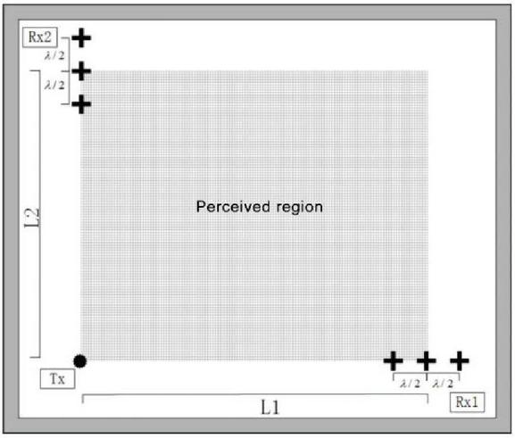
Figure 1 System model.
2 System Model
The purpose of this study is to use commercial Wi-Fi devices to track two-dimensional trajectories of human motion in an indoor environment, as shown in Figure 1. In the sensing application of Wi-Fi devices, the number of antennas is less and the signal-to-noise ratio is low. When tracking a moving human body, it is limited by the sampling rate (about 200 Hz). The number of snapshots (multiple CSI frames measured in a short period of time are regarded as measured in the same environment, and multiple snapshots in the time domain are used to make up for the lack of signal-to-noise ratio) is also less. When measuring signal AoA with the MUSIC algorithm, the resolution is limited by the array aperture at low signal-to-noise ratios and small snapshot counts. The commonly used Wi-Fi equipment with only three antennas is reconsidered. When measuring the signal AoA, a linear antenna array is used. When the antenna interval is the largest (), the antenna array has the largest aperture . In the Wi-Fi, the 2.4 GHz frequency band is about 0.12 m, and the 5 GHz band is only 0.06 m. This makes its angular resolution very low. Even when using the super-resolution MUSIC algorithm in the literature [17], the accuracy of AoA estimation is very low, and it is difficult to meet the requirements of tracking the two-dimensional trajectory of human motion in indoor environments.
However, the length change of the dynamic reflection path could be more accurately estimated in the complex plane trajectory analysis algorithm based on the CSI quotient. In the simplified model, when the dynamic reflection path increases or decreases by one wavelength and the reflection point (the human body) is half a wavelength away or closer to the starting device, the CSI quotient rotates one revolution in the complex plane. Therefore, the path variation length calculated by the complex plane trajectory algorithm based on the CSI quotient is more accurate, but its disadvantage is that the absolute length of the path could not be determined, so it is impossible to use this algorithm only to calculate the human motion trajectory.
The design idea of the system model in this paper is to use a relatively accurate CSI quotient complex plane trajectory analysis algorithm to obtain accurate relative change information of the human body reflection path length, and then fuse the AoA information obtained by the MUSIC algorithm with a large error, so as to calculate the precise absolute position information of the human body or the human body part and obtain the accurate estimation of the activity trajectory of the human body or the human body part. On the one hand, the results of AoA estimation provide absolute position information for the relative displacement information obtained by the CSI quotient complex plane trajectory analysis algorithm. On the other hand, the relative displacement information obtained by the CSI quotient complex plane trajectory analysis algorithm can average the AoA results over the time span of the entire motion trajectory, reducing the impact of the low accuracy of the AoA estimation algorithm on the results.
3 Spatial Trajectory Estimation Based on CSI Quotient
The spatial trajectory estimation based on the CSI quotient is an important module of the passive indoor trajectory tracking system based on Wi-Fi designed and implemented in this paper. The CSI quotient is used to estimate the length change of the dynamic reflection path, which is the ToF change information of the reflected signal of the human body. Then, the precise relative displacement information is calculated.
3.1 CSI Quotient Model
The CSI quotient is proposed in the literature [17] that the CSI data collected by two receiving antennas connected to the network card of the same receiving equipment and close to each other in space are calculated to obtain the CSI quotient data processing method. Due to the existence of CSI noise, it is very difficult to directly use CSI data to extract and analyse human multipath features. In contrast, the CSI quotient data obtained from CSI quotient processing retain the geometric characteristics of CSI data on the complex plane, while greatly reducing the amplitude and phase noise. In this paper, the CSI quotient data are used to calculate the path length variation.
The mathematical model of the CSI quotient is as follows:
| (1) |
Thereinto, and are the CSI data of the subcarrier number received on the first and second antennas in the first CSI data frame respectively. is the amplitude and phase noise in the first CSI data frame, since the same network card receives the same frame of data and the noise part is exactly the same for the two antennas. and are the amplitude and phase of the dynamic path in the CSI data received by the two antennas respectively. and represent the amplitude and phase of the static path in the CSI data received by the two antennas. in the simplified result represents the phase difference of the dynamic path on the two antennas. It could be seen that the CSI quotient can theoretically play a role in suppressing the amplitude and phase noise introduced by the wireless network card in the process of receiving signals. In addition, in the processing of actual data, the CSI quotient is also very effective in suppressing glitches and fluctuations in the data.
The literature [17] points out that the simplified result of Equation (3.1) could be approximated as , the Möbius transform of this term on the complex plane, which could be regarded as its translation, scaling, mirroring and inversion transformation on the complex plane. On the complex plane, represents an arc with a rotation angle . If the arc does not contain the origin after translation and scaling, its rotation direction remains unchanged after Möbius transformation. Therefore, the CSI quotient data retain the geometric characteristics of the dynamic components in the CSI data on the complex plane. The amplitude and phase characteristics of the dynamic path components contained in the CSI data could be extracted and analysed by analysing the CSI quotient.
The collected CSI data is first calculated by the ratio between the receiving antennas on each frame and each subcarrier to obtain the CSI quotient on each frame and each subcarrier, and to be averaged among the subcarriers. Some sub-carriers in the actual received data are of poor quality, and there are problems such as inconspicuous reflection on the dynamic path, too small amplitude or serious noise. The operation of averaging between sub-carriers weakens the influence of these sub-carriers, and also enhances system stability.
| (2) |
In contrast, the original CSI data are very messy on the complex plane, while the trajectory of the CSI quotient on the complex plane is related to the dynamic path and is relatively regular. It could be seen that, in the measured data, the CSI quotient could process the CSI data to such an extent that its dynamic path features could be extracted by analysing its geometric features on the complex plane for subsequent algorithm processing.
3.2 Complex Plane Trajectory Analysis Algorithm
The above dynamic path features are mainly manifested in the correlation between the dynamic path length variation and the rotation angle of the complex plane CSI quotient trajectory.
| (3) | ||
| (4) |
In Equation (3.2), is the sum of static path components, is the amplitude and phase of the dynamic path with the largest amplitude and moderate frequency, is the wavelength and is the path length respectively. The static component includes the direct path component and the reflected path component of all static objects, as well as the reflected path component of objects that move slowly and are considered stationary for a short time. According to the theoretical derivation of the CSI quotient in Section 3.1, the CSI quotient in Equation (4) could be expressed as the offset of the scaled dynamic path trajectory on the complex plane, which is a complex number.
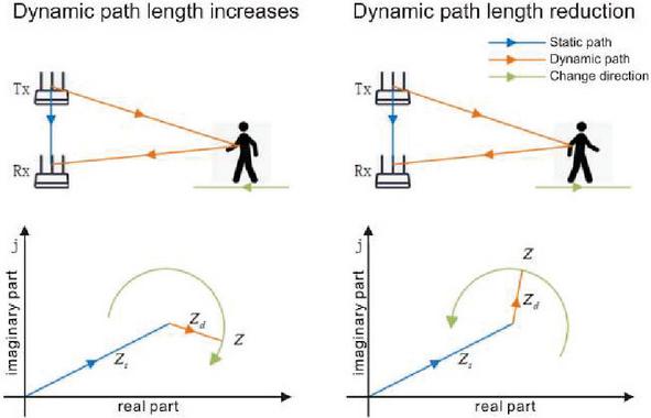
Figure 2 Schematic diagram of trajectory model on complex plane of CSI quotient.
As shown in Figure 2, on the complex plane , the static path component of the CSI quotient is represented, represents the dynamic path component of the CSI quotient, and represents the CSI quotient. When the reflection path grows, the CSI quotient trajectory on the complex plane rotates clockwise to form an arc centered on the circle . On the contrary, when the reflection path is shortened, the CSI quotient trajectory on the complex plane is a counter clockwise arc.
The dynamic components contained in the actual collected CSI data usually include multiple dynamic paths, such as the dynamic paths reflected by different body parts of the human body, the reflection paths of the human body that are re-reflected by objects such as walls, and the dynamic paths caused by other moving objects in the environment. These extraneous path components are usually smaller in magnitude and higher in frequency than the body reflected path, causing glitches and jitters. Alternatively, they are lower in frequency, causing a slow drift of the offset .
The input of the algorithm is the CSI quotient. The algorithm flow is shown in Figure 3.
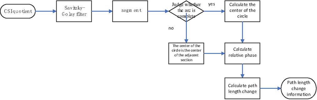
Figure 3 The complex plane trajectory analysis algorithm.
Firstly, the trajectory jitter caused by high-frequency components is filtered out by the Savitzky-Golay filter, then the maximum value of its imaginary part is used to segment, and the entire trajectory on the complex plane is divided into several arcs. The segmented results include inferior arc segments whose shape is close to a circle, and superior arc segments generated by the change of the path length variation trend. For inferior arc segments, the average method is used to find the center of the circle. For superior arc segments, the center of adjacent superior arc segments is directly used by utilizing the slow change of static and low-frequency path components. Next, the relative phase corresponding to each point on the arc is calculated according to the center of each arc. Then, the dynamic path phase is calculated. Finally, the dynamic path length is calculated according to Equation (5).
| (5) |
It should be noted that is obtained to only represent the increment of the dynamic component phase in the first frame of CSI (Channel State Information) data relative to the dynamic component phase in the first frame of CSI (Channel State Information) data. So is obtained to represent the relative change information of the dynamic path length, not the absolute path length.
3.3 Computation of Space Trajectories
In the above algorithm, the path length of the wireless signal reflected by the dynamic object in space could be obtained. In order to obtain the spatial trajectory of the dynamic object that is from the human body, we also need to use the spatial position of the transceiver device, in addition to the reflection path length of the human body. The scenario of indoor two-dimensional trajectory estimation of the human body is considered. For the reflection path length on a pair of transceiver devices, single-dimensional information could be only used. The position estimation is limited to an ellipse, and the specific position of the human body on the ellipse could not be measured. Therefore, two pairs of transceivers are used to receive. In order to conveniently use the path length to calculate the position information, two transceiver pairs are arranged in a horizontal plane, and their direct transmission paths are perpendicular to each other, as shown in Figure 4.
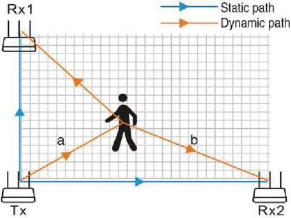
Figure 4 Path diagram.
In the scenario shown in Figure 4, the transmitting device Tx and the two receiving devices Rx1 and Rx2 are used, and the effective trajectory tracking range is the area marked by the shadow. The result of the above algorithm is the relative change information and of the reflection path length.
| (6) |
Thereinto, and are the lengths of the reflection paths on the two pairs of transceiver devices respectively, which are the distance from the reflective object (human body) to the transmitting device, and the sum of the distances from the reflective object to the receiving device. Corresponding to a+b in Figure 4, and respectively represent the initial values of the lengths of the two reflection paths.
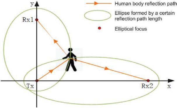
Figure 5 Schematic diagram of path length calculation location.
A Cartesian plane rectangular coordinate system is established on the plane where the two transceiver pairs are located. The lines where Tx-Rx1 and Tx-Rx2 are located are respectively used as the x and y axes, as shown in Figure 5. From the spatial position relationship, the following equations could be obtained:
| (7) |
Thereinto, is the coordinate of the sending device Tx. and are the coordinates of the sending devices Rx1 and Rx2 respectively. According to the equation system, is the coordinate of the reflecting object at the moment . In fact, this system of equations describes the intersection of two ellipses with Tx, Rx and Tx, Rx2 as the focuses respectively, as shown in Figure 4. There are two or more intersection points. The meaningful intersection positions could be distinguished by judging according to the effective tracking range.
It should be noted that the initial values and of the reflection path length are assumed to be known here. The determination method involves the results of the AoA estimation, which will be introduced in the Section 4.2.
4 AoA Estimation Based on Music Algorithm
4.1 Improved MUSIC Algorithm for Joint Estimation of AoA and ToF
For applying the MUSIC algorithm to the Wi-Fi passive positioning system, there are the following challenges:
• Insufficient resolution due to the limited number of Wi-Fi antennas:
Common commercial Wi-Fi devices generally have fewer antennas. In the research in the field of Wi-Fi perception, the more Wi-Fi wireless network cards Intel 5300 NIC are widely used as an example. This network card supports up to 3 antennas for sending or receiving. The maximum number of antennas in the antenna array is used for the MUSIC algorithm. The covariance matrix of the antenna array output signal obtained in the MUSIC algorithm is an order square matrix . Therefore, the noise space is removed in the process of applying the MUSIC algorithm, and the signal space could accommodate at most two eigenvectors. In an indoor environment, due to the reflection of objects such as walls, floors and human bodies, the number of Wi-Fi signal multipaths is often greater than two. Therefore, the classic MUSIC algorithm could not accurately estimate and distinguish the signal AoA in an indoor environment.
• It is difficult to effectively select the reflection path of the human body in a multipath environment:
In the results of the MUSIC algorithm, the sources of AoA are messy. It is difficult to distinguish the AoA of the human body reflection path only based on the AoA information estimated by the classical MUSIC algorithm.
• Insufficient utilization of subcarrier dimension information:
The CSI information has a small length in the antenna array dimension (only three antennas), but a large length in the frequency dimension (for example, the Intel 5300 NIC could measure the CSI value at the center frequency of 30 subcarriers). The classic MUSIC algorithm only utilizes the dimension of the antenna array, but could not make good use of the information in the dimension of the subcarriers in the CSI.
Faced with these problems, this research refers to the literature [13] of the construction of a virtual antenna array. The super-resolution AoA estimation is completed by the MUSIC algorithm with spatial smoothing. The frequencies of all 30 sub-carriers on the three antennas in the CSI data are used to form a virtual antenna array. The received signal matrix is constructed with the spatial smoothing technology. Specifically, the received signal matrix is expressed as:
Correspondingly, the steering vector A corresponding to the spatial spectral function in the super-resolution ToF-AoA MUSIC algorithm is also expressed as follows:
| (9) |
Thereinto, represents the phase shift caused by the signal of AoA between two antennas with distance . represents the phase shift of a signal on the sub-carrier numbered, it is as relative to the sub-carrier 1 numbered.
Correspondingly, the peak search is performed on the two-dimensional spatial spectral function. The AoA and ToF corresponding to a series of peaks are the joint estimation results of AoA and ToF.
4.2 AoA Matching and Dynamic Path AoA Selection Algorithm
In the above-mentioned AoA-ToF estimation algorithm based on the MUSIC algorithm, the AoA of the signal arriving at the Wi-Fi antenna array from each frame of the original CSI data is analyzed. Several AoA estimates are outputted in each frame to form multipath AoA map within a period of time. The data required for trajectory tracking are the target object, which is the human body. There is the trajectory information within a period of time and the position of the target object at each moment in the time period. Specifically, for a series of results of the MUSIC algorithm, it is necessary to match the AoA estimation results of the same signal source in each two adjacent frame results in terms of time sequence, and obtain the time sequence AoA of each path for further processing.
In addition, the results of the MUSIC algorithm also include multiple paths other than the human body reflection path and the AoA estimation results corresponding to the error results generated by noise. It is necessary to reduce the influence of noise. Then, the AoA estimate corresponding to the human body reflection path is selected according to the changes.
This paper refers to the methods in the literature [10], introduces the model of graph theory for modeling, and converts the path matching problem into a binary integer programming (Binary Integer Programming, BIP) to solve.
That each frame containing AoA-ToF estimates is considered. The AoA-ToF map is composed of frame AoA-ToF data. The AoA-ToF estimates of a series of frames resulting from the MUSIC algorithm are regarded as vertices. The relationship between AoA-ToF estimates of adjacent frames is regarded as an edge. The weights represent the influence of possible edges on the planning problem goal. The path matching problem is to add connecting edges between the vertices corresponding to the AoA estimates of the same path in adjacent frames. The connected subgraphs are formed. Each subgraph represents the AoA estimate of a path in the frame measurement.
Specifically, an undirected weighted graph is defined to build the model.
is the set of vertices and is represented by a matrix whose element represents the AoA-ToF estimate in the frame .
is a set of edge and is represented by an adjacency matrix whose element is 0 or 1. They indicate that there are respectively connected and unconnected edges between vertices. In this problem, there are the two following constraints. Firstly, there are only connected edges between the vertices of adjacent frames. This constraint is reflected in the definition of the adjacency matrix . Secondly, it is necessary to find a perfect match between the AoA-ToF estimates of adjacent frames. That is a one-to-one matching relationship, which is expressed as the following constraints:
| (10) |
represents the edge weight. The matching of AoA-ToF estimates between adjacent frames is based on AoA and ToF estimates. Due to the high sampling rate, the difference between AoA and ToF of the same path between adjacent frames is less. The AoA and ToF distances are used as planning targets. The weight matrix is defined. The matrix elements are calculated as follows:
| (11) |
Thereinto, and represent the weights to consider AoA and ToF in the planning problem.
The planning objective function for the BIP(Binary Integer Programming)could be defined according to the above model:
| (12) |
The binary adjacency matrix is used as the planning variable and is used as the objective function to solve the BIP problem under the constraints of Equations (10). The path matching of the AoA-ToF map is completed according to the planning results.
Finally, the Hamp filter is used to filter out outliers for the matching results of each path. According to the actual situation, the AoA information of the path within the target perception area and the fluctuation level closest to the human body is selected as the estimation of the AoA sequence of the human reflection path to complete the path selection.
5 Fusion Algorithm and System Design
The super-resolution MUSIC algorithm and the complex plane trajectory analysis algorithm used in the system, as well as the path matching and trajectory calculation methods used to process the results of the both have been introduced in the previous in detail. The principle and implementation method of the fusion algorithm are introduced here.
Compared with the AoA information estimated by the super-resolution MUSIC algorithm, the results and of the complex plane trajectory analysis algorithm have great advantages in accuracy and reliability. Therefore, in the fusion algorithm, the AoA information is used to determine the initial value of the path length and . The final result of the human motion trajectory is calculated with the initial path length , and the path change information , .
The key to the fusion algorithm lies in the determination of the initial path length. For a piece of CSI data, a set of initial path lengths is found, so that the dynamic path AoA estimation result matches the path calculated with this set of initial path length and dynamic path length change estimation to the greatest extent. In this paper, the initial path lengths and are set as the optimization variables. A loss function is defined to calculate the trajectory difference between AoA and dynamic path length under this set of initial path length assumptions. Finally, the optimizer provided by Scipy is used to obtain the initial path length as its estimate, which minimizes the loss function.
The algorithm steps are as follows:
Step 1. Determine the initial path length Define the loss function:
| (13) |
Thereinto, and are the calculation results of the AoA of the two receiving antenna arrays by the MUSIC algorithm. and are the trajectories calculated from the path lengths determined by the complex plane trajectory analysis algorithm, when the initial path lengths on the two receiving antenna arrays are assumed to be and respectively. The AoA is calculated under the known antenna placement.
Specifically, a set of initial path lengths is given to obtain the absolute path lengths and under the assumption:
| (14) |
Then, according to the above trajectory calculation method, the trajectory under this assumption is calculated on the basis of the following equations:
| (15) |
Respectively calculate and according to the trajectory and the coordinates and orientation of the receiving antenna. Then recalculate the value of the loss function.
According to the above principle, the value of the initial path length is determined by taking as the optimization variable and the function as the optimization objective.
| (16) |
Step 2. Calculate the motion trajectory Determine the absolute length of the dynamic path according to the initial length of the path. Calculate the motion trajectory according to the intersection equation of the two ellipses expressed in Equation 3.7.
6 Test Results and Performance Analysis
6.1 Performance Analysis of Trajectory Estimation Module Based on CSI Quotient
In order to analyze the feasibility and accuracy of the CSI quotient-based trajectory estimation algorithm in human tracking scenarios, the simulation data of indoor human tracking scenarios are used in this paper to test the module in two frequency bands 2.4 GHz and 5 GHz. In the CSI quotient trajectory estimation module experiment with simulated data, the average error in the 5 GHz band is 29.2 cm, and the median is 24.1 cm. The average error in the 2.4 GHz band is 9.4 cm, and the median is 5.8 cm. The CDF statistics of the errors are shown in Figure 6.
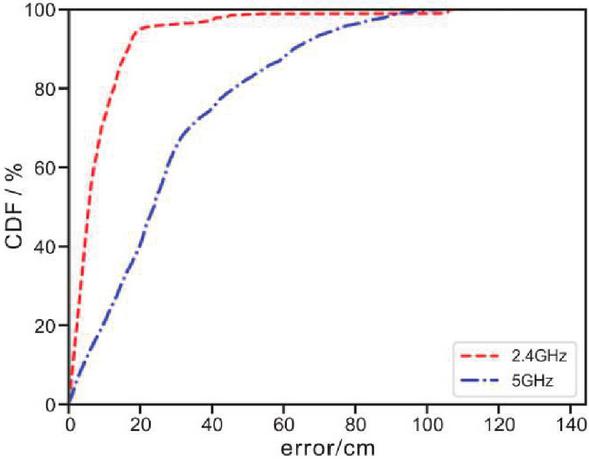
Figure 6 Error cumulative distribution function of trajectory estimation based on CSI quotient.
In the simulation results, the centimeter-level error is achieved in the 2.4 GHz frequency band, and the effect is significantly better than that of 5 GHz. The main reason is that the wavelength of the 5 GHz band is short, and the phase of the dynamic component of the CSI quotient changes too fast when the dynamic path length change rate is larger. Under the limited sampling frequency (200 Hz), the complex plane trajectory analysis algorithm could not effectively track its phase.
6.2 Performance Analysis of AoA Estimation Module Based on MUSIC Algorithm
In order to test the feasibility of the AoA estimation module and further analyze the improvement of the system design for the AoA-based positioning scheme in this paper, the dynamic path AoA estimation error of the super-resolution MUSIC algorithm and the path matching selection algorithm used in the trajectory tracking system is tested in this paper. In addition, the trajectory estimation error is calculated with the above AoA estimation results.
In the test of the AoA estimation module based on the MUSIC algorithm, the simulation data is used as the test data, and the No. 12 channel of the 2.4 GHz frequency band is used.

Figure 7 Error cumulative distribution function of AoA estimation.
Error cumulative distribution function of the simulation test estimated by AoA is shown in Figure 7. The average error is 14.4, and the median error is 12.2. AoA still has a larger error in an ideal simulation environment. This indicates that the AoA-ToF joint estimation based on the MUSIC algorithm could not stably distinguish and estimate the dynamic path AoA, due to the limitations of small aperture of the antenna array, low signal-to-noise ratio, and the fact that the direct transmission signal and the reflected signal could not fully meet the unrelated requirements.
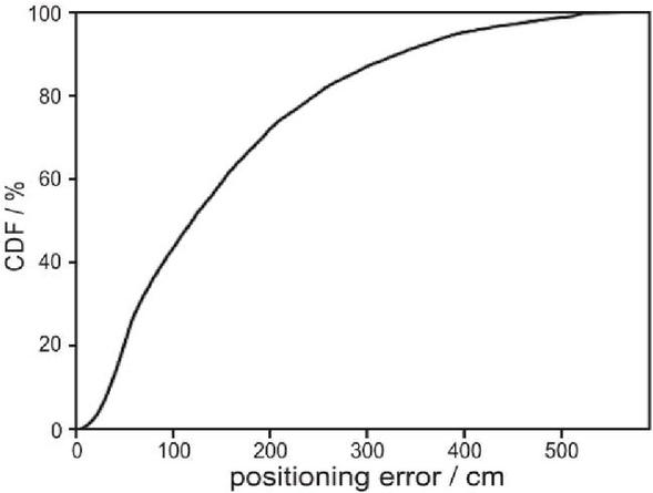
Figure 8 Error cumulative distribution function of positioning method based on AoA.
The cumulative distribution function of trajectory estimation simulation test error based on AoA estimation is shown in Figure 8. The average error is 1.53 m, and the median error is 1.20 m. The effective sensing area with 5 m * 5 m is considered. The average error and the median error in such an area are more than 1 m. This indicates that the trajectory estimation method based on the AoA-ToF super-resolution MUSIC algorithm AoA estimation has little practical significance in the indoor passive tracking scene.

Figure 9 Example of estimates of AoA.
Figure 9-left is the AoA estimation result of a piece of simulation data. Figure 9-right is the trajectory estimation based on AoA estimation. It could be seen that in the process of AoA estimation to calculate the trajectory, the error of AoA estimation is significantly enlarged. It is not feasible for the above AoA estimation algorithm to be directly used for trajectory calculation, but in the most time periods, the results of AoA estimation are distributed on the both sides of the reference value. Therefore, an estimation of the initial position could be provided in the system.
6.3 Overall System Performance Analysis
The simulation data are used to test the indoor passive human trajectory tracking system designed in this paper.
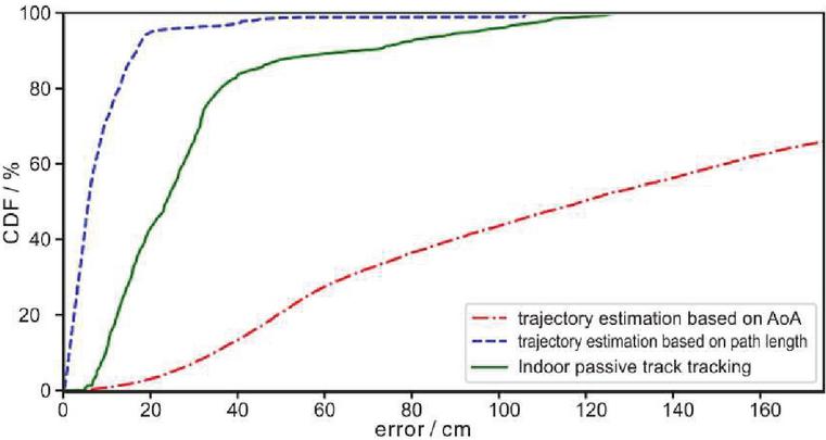
Figure 10 Error cumulative distribution function of the indoor passive trajectory tracking system.
Figure 10 is shown that the mean and median values of the system simulation test errors are 30.3 cm and 23.8 cm respectively. The both reach the level on decimeter, which has high application value in indoor passive human trajectory tracking scenarios.
AoA-based trajectory estimation, trajectory estimation based on path length and initial position with reference data, and the comparison of the mean and median errors of indoor passive trajectory tracking systems are shown in the Table 1.
Table 1 Based on AoA, the estimation error statistics based on the path length and the overall trajectory of the system
| Estimation Method | Trajectory Estimation Based on AOA | Based on the Path Length, the Initial Position is Estimated with the Trajectory of the Reference Data | Indoor Passive Track Tracking System |
| Average error /cm | 153.0 | 9.4 | 30.3 |
| Median error /cm | 119.9 | 5.8 | 23.8 |
According to the statistical results shown in Figure 10 and Table 1, the simulation test error of the system is much better than the trajectory calculation method based only on AoA and slightly worse than the trajectory estimation based on the path length and the initial position with the reference data. This proves that the complex plane trajectory analysis algorithm based on CSI quotient is used in the system design to achieve higher accuracy. The design of the AoA estimation based on the MUSIC algorithm to determine the absolute position has achieved the expected purpose. At the same time, the larger error of the AoA estimation part causes a more limitation on the accuracy of the final trajectory estimation.
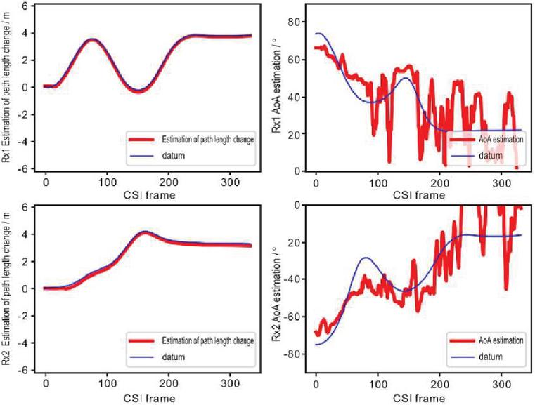
Figure 11 Example of passive indoor track tracking system module results.
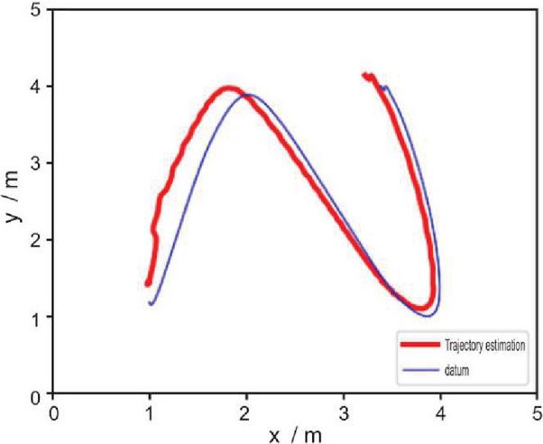
Figure 12 Example of trajectory estimation for passive indoor trajectory tracking system.
Respectively. Figures 11 and 12 are the example of system module result and the example of system final trajectory estimation result. It could be seen that the final trajectory estimation result of the system achieves high accuracy, and the trend and direction of motion trajectory are well preserved to fully prove the practical value of the system.
7 Conclusions
Based on the CSI quotient-based trajectory estimation algorithm and the AoA-ToF estimation algorithm, a framework of the passive indoor trajectory tracking system based on Wi-Fi is designed and implemented. The system uses the CSI quotient complex plane trajectory analysis algorithm to obtain the relative displacement information, and combines the super-resolution MUSIC algorithm to obtain the absolute position estimation to calculate the human motion trajectory. In the verification experiment, the trajectory estimation module based on the CSI quotient achieves centimeter-level accuracy in the arm trajectory tracking scene. In the simulation performance analysis, the indoor motion trajectory estimation of the human trunk of the whole system has reached the decimeter level positioning accuracy. Therefore, the effect has reached the expectation.
Acknowledgments
This work was supported by the R&D Program of Beijing Municipal Education Commission (NO. KM202110858003). The authors would like to thank the associate professor Zhaoming Lu who is working at Beijing University of Posts and Telecommunications (P.R China) in particularly for the support in thesis examination and guidance. The authors are also grateful to the teacher Luhan Wang of OAI WORKSHOP.
References
[1] N. Keerativoranan, P. Hanpinitsak, K. Saito and J. -I. Takada, ‘Analysis of Non-Intrusive Hand Trajectory Tracking by Utilizing Micro-Doppler Signature Obtained From Wi-Fi Channel State Information’, In IEEE Access, vol. 8, pp. 176430–176444, Sep., 2020.
[2] W. Liu et al., ‘Survey on CSI-based Indoor Positioning Systems and Recent Advances’, IPIN Int. Conf. on Indoor Positioning and Indoor Navigation., Pisa, 2019.
[3] X. Li and J. Zhu, ‘Improved Indoor Positioning Method Based on CSI’, ICITBS Int. Conf. on Intelligent Transportation, Big Data & Smart City., Changsha, 2019.
[4] F. Han, C. Wan, P. Yang, H. Zhang, Y. Yan and X. Cui, ‘ACE: Accurate and Automatic CSI Error Calibration for Wireless Localization System’, BIGCOM Int. Conf. on Big Data Computing and Communications., Deqing, 2020.
[5] F. Thalmann, A. P. Carrillo, G. Fazekas, G. A. Wiggins and M. Sandler, ‘The Mobile Audio Ontology: Experiencing Dynamic Music Objects on Mobile Devices’, ICSC Int. Conf. on Semantic Computing., CA, 2016.
[6] P. Gallo, S. Mangione and G. Tarantino, ‘WIDAR: Bistatic WI-fi Detection And Ranging for off-the-shelf devices’, WoWMoM Int. Conf. on A World of Wireless, Mobile and Multimedia Networks., Madrid, 2013.
[7] Y. Jin, Z. Tian, M. Zhou and H. Wang, ‘MuTrack: Multiparameter Based Indoor Passive Tracking System Using Commodity WiFi’, ICC Int. Conf. on Communications., Dublin, 2020.
[8] A. Pearce, J. A. Zhang and R. Xu, ‘Regional Trajectory Analysis through Multi-Person Tracking with mmWave Radar’, RadarConf22 Int. Conf., NY, 2022.
[9] W. Dan, Z. Daqing, et al., ‘WiDir: walking direction estimation using wireless signals’, ACM Int. Conf. on pervasive and ubiquitous computing., Heidelberg, 2016.
[10] K. Qian, C. Wu, Y. Zhang, et al., ‘Widar2. 0: Passive human tracking with a single wi-fi link’, MobiSys Int. Conf. on Mobile Systems, Applications, and Services. Munich, 2018.
[11] Y. Zheng, Y. Zhang, K. Qian, et al., ‘Zero-effort cross-domain gesture recognition with Wi-Fi’, MobiSys Int. Conf. on Mobile Systems, Applications, and Services., Seoul, 2019.
[12] R. Schmidt, ‘Multiple emitter location and signal parameter estimation’, in IEEE Transactions on Antennas and Propagation, vol. 34, no. 3, pp. 276–280, March., 1986.
[13] K. Manikanta, J. K. Raj, B. Dinesh, et al., ‘Spotfi: Decimeter level localization using wifi’, SIGCOMM Int. Conf. on Special Interest Group on Data Communication., London, 2015.
[14] C. R. Karanam, B. Korany and Y. Mostofi, ‘Tracking from One Side – Multi-Person Passive Tracking with WiFi Magnitude Measurements’, IPSN Int. Conf. on Information Processing in Sensor Networks., QC, 2019.
[15] X. Li, D. Zhang, Q. Lv, et al., ‘IndoTrack: Device-free indoor human tracking with commodity Wi-Fi’, In Proceedings of the ACM on Interactive Mobile Wearable and Ubiquitous Technologies, vol. 1, no. 3, pp. 1–22, Sep., 2017.
[16] X. Li, S. Li, D. Zhang, et al., ‘Dynamic-music: accurate device-free indoor localization’, UbiComp Int. Conf. on Pervasive and Ubiquitous Computing., Heidelberg, 2016.
[17] Y. Zeng, D. Wu, J. Xiong, et al., ‘Farsense: Pushing the range limit of wifi-based respiration sensing with csi ratio of two antennas’, In Proceedings of the ACM on Interactive, Mobile, Wearable and Ubiquitous Technologies, vol. 3, no. 3, pp. 1–26, Jul., 2019.
[18] Y. Xie, Z. Li, M. Li, ‘Atheros CSI Tool’, MobiCom Int. Conf. on Mobile Computing and Networking., Paris, 2015.
[19] L. Xiang, Z. Daqing, L. Qin and et al., ‘IndoTrack: Device-free indoor human tracking with commodity Wi-Fi’, In Proceedings of the ACM on Interactive, Mobile, Wearable and Ubiquitous Technologies, ACM, vol. 1, no. 72, pp. 1–22, Sep., 2017.
[20] K. Qian, C. Wu, Y. Zhang, et al., ‘Widar2.0: Passive Human Tracking with a Single Wi-Fi Link’, MobiSys Int. Conf. on Proceedings of the 16th Annual International Conference on Mobile Systems, Applications, and Services., Munich, 2018.
Biographies

Wei Han is an Associate Professor at Beijing Polytechnic and has Master degree in electrical automation by Southwest Jiaotong University. Her current research interests focus on Electronic Information Engineering Technology, Big data technology and application, Artificial Intelligence Application Technology.

Shenggang Wu is a Professor at Beijing Polytechnic and has master’s degree by Shandong University. His current research interests focus on image processing, intelligent systems, machine learning, emotion recognition, multi-source information fusion, and natural language processing.
Journal of ICT Standardization, Vol. 11_1, 1–26.
doi: 10.13052/jicts2245-800X.1111
© 2023 River Publishers