A Trusted Model of Complex Computer Networks
Andrey A. Shchurov and Radek Marik
Department of Telecommunication Engineering, Czech Technical University
in Prague, Faculty of Electrical Engineering, Technicka 2,
Prague 6 - Dejvice, 166 27, Czech Republic
E-mail: {shchuand; marikr}@fel.cvut.cz
Received 1 March 2016;
Accepted 26 May 2016
Abstract
Formal methods based on abstract models are becoming more and more important in the domain of complex computer networks. On the other hand, processes of design documentation transformation into the formal models are still bound to the skills and ingenuity of individual engineers. Moreover, the human factor involved in data transformation represents a major bottleneck due to the tendency of computer networks to be more and more complex. To address this problem, this work introduces a formal model based on the concept of multilayer networks for applying a system methodology to network analysis and an appropriate presentation format of architecture descriptions as a possible part of detailed design documentation that could allow automated generation of trusted formal multilayer models based on this documentation.
Keywords
- computer networks
- design documentation
- formal models
- multilayer networks
1 Introduction
Formal methods are mathematical techniques for developing software and hardware systems and can be used to conduct mathematical proofs of consistency of specification and correctness of implementation. Mathematical rigor enables users to analyze and verify abstract models at any part of the system life-cycle: requirements engineering, architecture design, implementation, maintenance and evolution [43]. These methods are particularly suitable for complex heterogeneous systems (including computer networks) and are becoming more and more important.
However, model analysis requires specialized training, both in the models development – a model must be completely relevant to a system (a trusted model) – and in the interpretation of the analysis results. As a consequence, it depends on the qualification, ingenuity and intuition of individual engineers. The human work involved in data transformation represents a major bottleneck due to its tendency to be relatively unsophisticated and repetitive, but persistently tricky and time-consuming at the same time [25]. Challenges in the analysis process that repeatedly occur in analysis efforts are: (1) discover necessary data; (2) wrangle data into a desired format; (3) profile data to verify its quality and suitability; and (4) report procedures to consumers of the analysis.
Thus, to get full advantages of model analysis and verifying in the domain of complex systems, it is necessary to alleviate the burdens of learning model development and checking techniques for engineers and other non-technical stakeholders [17] or, ideally, completely eliminate the human factor. There have been some attempts to make model development accessible to those who are not trained in formal methods. These include Formal Description Techniques (FDT) [7] based on a technical language for unambiguous specification and description of the behavior of telecommunication systems. However, FDTs are intended to specify the behavioral aspects of software-intensive systems only; the general parameters, which determine heterogeneous architectures, have to be described using different techniques.
To address this problem, this work proposes: (1) a formal model which specifies heterogeneous structures and their properties based on the concept of multilayer networks for applying a system methodology to network analysis; and (2) an appropriate presentation format of architecture descriptions as a possible part of the detailed design documentation of complex computer networks, which could allow automated generation of the formal multilayer model based on this documentation (i.e. the human factor could be eliminated from the model generation process).
The rest of this paper is structured as follows. Section 2 presents the background and related work. Section 3 introduces the formal model based on the concept of multilayer networks. Section 4 focuses on the presentation format of architecture descriptions and the correlation between this format and the formal model. Section 5 considers the limitations of the proposed approach. In turn, Section 6 represents a case study. Finally, conclusion remarks are given in Section 7.
2 Related Work
Applying a system methodology to network analysis [33] is a relatively new approach, particularly in the Internet Protocol (IP) world. The fundamental concept is that network architecture should take into account services/applications which this network provides and supports. It is important to note that this concept is completely supported by the most recent practical approaches such as Business-Driven Design [41] and Application Centric Design [24].
In the context of this work, the background covers the following main areas:
- Formal models which can represent both: (1) software-based; and (2) network-based aspects of complex computer networks with regard to applying the system methodology to network analysis.
- Design documentation as the data source for model development.
2.1 Formal Models
One of the major goals of modern physics is providing proper and suitable representations of systems with many interdependent components, which, in turn, might interact through many different channels. As a result, interdisciplinary efforts of the last fifteen years have led to the birth of complex networks theory [18, 34, 37] including the concept of multilayer networks [20, 23, 27] that explicitly incorporate multiple channels of connectivity and constitute the natural environment to describe systems interconnected through different types of connections: each channel (relationship, activity, category, etc.) is represented by a layer and the same node or entity may have different kinds of interactions (different set of neighbors in each layer). Assuming that all layers are informative, multilayer networks can provide complementary information. Thus, the expectation is that a proper combination of the information contained in the different layers leads to a formal network representation (a formal model) appropriated for applying the system methodology to network analysis.
Recent surveys in the domain of multilayer networks provided by Kivela et al. [27] and Boccaletti et al. [20] give a comprehensive overview of the ex-isting technical literature and summarize the properties of various multilayer structures1.
In the context of this work, the multilayer approach for the modeling of complex computer networks covers two areas:
- multilayer model itself;
- layers definitions.
2.1.1 Multilayer model
A type of multilayer network of particular relevance for computer networks is a hierarchical multilayer network [27], in which the bottom layer constitutes a physical network and the remaining layers are virtual layers that operate on top of the physical layer. Hence, the formal definitions of multilayer networks [20, 27] can be used as a starting point. However, these definitions support a wide spectrum of arbitrary relationships between different layers. The necessary condition of top-down consistency can be provided by the concept of layered networks [28]. In turn, this concept is based on the facts:
- for each node on a given layer there is a corresponding node (or nodes) on the layer below;
- for each path between two nodes on a given layer there is a path (or paths) between the corresponding nodes on the layer below.
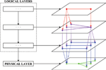
As a consequence, the formal basic definition should be adapted to the hierarchical top-down approach and the multilayer model of computer networks [35] can be used as a starting point (see Figure 1).
2.1.2 Layer definitions
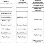
The ISO/OSI Reference Model (OSI RM) [4] was developed years ago for application developers, equipment manufacturers and network protocol vendors as an open standard for constructing network devices and applications/services that can work together. The model partitions computing systems into seven abstraction layers: (1) Physical Layer; (2) Data Link Layer; (3) Network Layer; (4) Transport Layer; (5) Session Layer; (6) Presentation Layer; and (7) Application Layer. However, this conceptual model has never been implemented in practice. Instead, the increasing popularity of TCP/IP based networking has led hardware and software developers to use the TCP/IP Protocol Suite (or Five-layer Reference Model) [22, 30, 39], the five layers of which are based on OSI RM – Layers 5 through 7 are collapsed into the Application Layer. IETF standards RFC 1122 [2] and RFC 1123 [3] define the TCP/IP Reference Model. This model is compatible with OSI RM and TCP/IP Protocol Suite but it partitions computing systems into four abstraction layers – layer 1 (Physical Layer) is removed from the model. Moreover, a common joke is that OSI RM should have three additional layers [32]: (8) User Layer; (9) Financial Layer; and (10) Political Layer. In practice, complex computer networks focus on solving problems at Layer 10 (but they are usually limited by Layer 9).
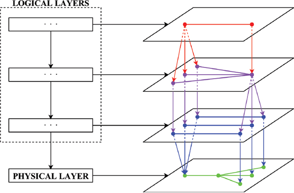
Figure 1 Hierarchical multilayer model [35].
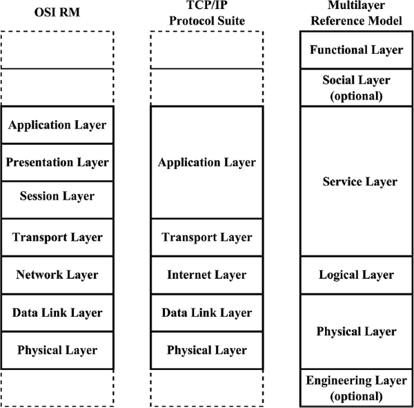
Figure 2 ISO/OSI Reference Model [4], TCP/IP Protocol Suite [22, 30, 39] and Multilayer reference model [35].
In turn, (in contrast to the developer community) the business community (end-users) faces the following challenges [35]:
- The fact that Physical Layer and Data Link Layer cannot be separated in the case of commercial off-the-shelf (COTS) network equipment.
- The fact that Transport Layer and Application Layer cannot be separated in the case of COTS software.
- The fact that end-users do not need services and applications themselves – they need tools to solve their business problems. However, neither OSI RM nor TCP/IP Protocol Suite provides a layer to represent the increased viewpoint of end-users (business goals).
- The fact that the environment impact might be critical in some cases2.
The problem can be solved by the following additional layers [26, 35] (see Figure 2):
- The functional (or ready-for-use system) layer which represents functional components and their interconnections – the increased viewpoint of end-users/customers.
- The social environment layer (optional) which defines organization infrastructures or human networks [32, 42].
- The engineering environment layer (optional). The layer defines external engineering systems that are vital for normal operation of physical networks.
2.2 Design Documentation
The universal requirement for design documentation is simple – the documentation should be based on standards like a formal document. Generally, the choice between international and regional standards depends on the state and/or corporate legislation but, fortunately, the majority of regional standards replicate their international predecessors.
As mentioned above, the Formal Description Techniques [7] are based on a technical language for unambiguous specification and description of the behavior of telecommunication systems. The main FDTs include: Specification and Description Language (SDL) [11], Message Sequence Chart (MSC) [12], User Requirements Notation (URN) [13], and Testing and Test Control Notation (TTCN) [15]. However, FDTs are intended to specify the behavioral aspects of software-intensive systems only, not their architectures [11]. Furthermore, they do not cover the structure of design documentation.
The current revision of IEEE Std. 1362–1998 (R2007) [5] standard represents a Concept of Operations (ConOps). ConOps is a user-oriented document that describes characteristics of to-be-delivered systems from the end-users (or integrated systems) point of view. It also specifies recommended graphical tools (charts and diagrams).
The latest revision of ISO/IEC/IEEE Std. 15288:2015 [16] standard establishes a common process framework for describing the life cycle of man-made systems. It defines a set of processes and associated terminology for the full life cycle, including Architectural Design Process (or the process of elaboration of design documentation). In turn, the standard ISO/IEC/IEEE Std. 15289:2011 [10] specifies the purpose and content of service management information items (documentation). It defines the life cycle data of ISO/IEC/IEEE Std. 15288:2015 by relating tasks and activities to the generic types of information items such as descriptions and specifications (the main information components of design documentation). Furthermore, conceptualization of system architectures assists the understanding of the system essence and key properties pertaining to its behavior, composition and evolution, which in turn affect concerns such as the feasibility, utility and maintainability of the system. As a consequence, the standard ISO/IEC/IEEE Std. 42010-2011 [14] specifies architecture viewpoints, architecture frameworks and architecture description languages for use in architecture descriptions.
It is important to note that these international standards establish what should be contained in design documentation but not how: possible formats of information items or, at least, guidance on selecting appropriate presentations are NOT included in the scope of these standards.
3 Formal Multilayer Model
According to the work goals (see Section 1), this section represents a formal model which specifies heterogeneous structures and their properties based on the concept of multilayer networks for applying a system methodology to network analysis. As mentioned above (see Section 2.1.1), the proposed model is based on the formal basic definition of multilayer networks [20] adapted to the hierarchical top-down approach. In this case:
Definition 1 Let the graph M denote the complex computer network (i.e. the computer network and services/applications which this network provides and supports) as a multilayer projection network:
where M is a multi-layered 3D graph (see Figure 1), derived from the detailed design documentation; Gα is a labeled intralayer subgraph of M; Gα,(α-1) is an interlayer bipartite subgraph of M; and L is the number of graph layers (1 ≤ α ≤ L).
In turn:
Definition 2 Let the subgraph Gα denote a layer of M as follows:
where V α is a finite, non-empty set of network components on layer α; Eα ⊆ V α ×V α is a finite, non-empty set of intralayer component-to-component interconnections on layer α; is a vertex label set for layer α; and is an edge label set for layer α. In this case:
where ⊂ Sα is a finite non-empty set of specifications of network components (the set of supported communication protocols) that defines the label of the vertex of Gα; ⊂ Sα is a finite non-empty set of specifications of component-to-component interconnections (the set of used communication protocols) that defines the label of the edge of Gα ; and Sα is the universal set of all possible communication protocols on layer α defined by international standards (standard protocols) and vendors (proprietary protocols).
Definition 3 Let the subgraph Gα,(α-1) denote a cross-layer of M as follows:
where Vα is a finite, non-empty set of network components on layer α, V(α-1) is a finite, non-empty set of network components on layer (α - 1); and Eα,(α-1) ⊆ V α × V (α-1) is a finite, non-empty set of interlayer relations (projections) between components of the layer α (2 ≤ α ≤ L) and the layer below (α - 1).
It is important to note that the quality of formal methods based on abstract models is limited by the quality of these models [40]. Hence, the consistency of the formal model should be verified during the model generation process. In the context of this work, the definition of the model consistency strictly relies on the following notions:
- The definition of consistency as the ability of parts of a system or component to be asserted together without contradiction [8].
- The definition of a communication protocol as a set of conventions that govern the interaction of processes, devices, and other components within a system [8].
- The concept of layered networks [28], i.e. the fact that a node on a given layer depends on a corresponding node (or nodes) on the layer below (with the exception of the bottom layer).
- The fact that the existence of isolated components is strictly against the definitions of computer networks [39] and distributed systems [38].
These ideas are formalized in Criterion 1:
Criterion 1 The formal model based on the concept of multilayer networks is internally consistent on a given layer α iff:
- each vertex of intralayer subgraphs Gα is incident with at least one edge of Gα, i.e. d ( ∈ Gα) ≥ 1;
- each pair of adjacent vertices and of Gα which are incident with the edge ⟨,⟩ of Gα supports at least one common communication protocol, i.e. ⊆ ; ⊆ and ≠∅;
- each vertex of interlayer subgraphs Gα,(α-1)(2 ≤ α ≤ L) is incident with at least one edge of Gα,(α-1), i.e. d ( ∈ Gα,(α-1)) ≥ 1.
In other words, an occurrence of model inconsistency represents the existence of errors/bugs (at least one) in the detailed design documentation (technical specifications). As a consequence: (1) the design documentation should be corrected; and (2) the formal model should be re-built and then re-checked using Criterion 1.
In general, the proposed model is the layered 3D-graph which should be derived directly from the detailed design documentation. Different layers represent different (hardware, software, social, business, etc.) aspects of network architecture. In turn, interlayer relations: (1) represent the technological solutions which were used to build the network (virtualization, clustering, replication, etc.); and (2) make the layered model consistent. This model completely covers all layers of OSI Reference Model (moreover, it covers some additional layers beyond the OSI RM) and, as a consequence, both software-based and network-based aspects of computer networks with regard to applying the system methodology to network analysis.
Using this model and the graph theoretical metrics, both static and dynamic network analyses can be performed. The static analysis determines the characteristics of each layer based on the intralayer and interlayer topologies and covers the network infrastructure including: (1) individual components; and (2) component-to-component interactions on all coexisting architectural layers [26, 36]. In turn, the dynamic analysis (or fault injection simulation) provides a means for understanding how the network behaves in the presence of faults. The analysis includes two main steps: (1) successive removals of vertices and their incident edges from the formal model (fault injection experiments); and (2) impact assessments of those removals on the model consistency - disruption on an arbitrary layer might destroy a substantial part of the upper layer (or layers) that are mapped on it, rendering the whole network useless in practice [29].
It is important to note that the proposed formal model: (1) should be derived directly from the detailed design documentation; and (2) should be completely relevant to the design documentation. To address this problem, the next section introduces an appropriate presentation format of architecture descriptions which could allow automated generation of the formal multilayer model.
4 Presentation Format
As mentioned above (see Section 2.2), the current revisions of international standards establish what should be contained in design documentation but not how exactly. Nevertheless, Appendix I of ITU-T Recommendation L.72 [6] represents an example of a currently used presentation format of optical access network infrastructure descriptions 3. It is important to note that this format covers the physical architecture completely and the logical architecture partially. However, this format is optimized for representation network infrastructures and, as a consequence, cannot be used: (1) to define a whole/completed system (i.e. a computer network and services/applications which this network provides and supports); and (2) to represent technological solutions (hardware and software clusters, virtualization platforms, etc.) which are used to build the system.
To fill the gap, this section represents:
- a set of design patterns 4 for unambiguous architecture description as a possible part of the detailed design documentation;
- the correlation between these design patterns and the formal model.
4.1 Design Patterns
Based on Definitions 1–3 (see Section 3), the architecture of complex computer networks can be represented by three main design patterns (tables) on each layer:
Based on the concept of layered networks [28], the architecture of complex computer networks can be represented by three main design patterns (tables) on each layer:
- Layer component specification. The layer component specification design pattern is used for the components detail representation. This design pattern should cover: (1) system business goals for the functional layer; (2) persons or groups of persons for the social layer (optionally); (3) software-based components (services/applications) for the service layer; (4) virtual components (VM, VLAN, etc.) for the logical layer; (5) hardware-based components (equipment) for the physical layer; and (6) external engineering systems for the engineering layer (optionally). The unified table column structure specifies the necessary component properties and, therefore, includes (see Table 1):
- Record Number.
- Layer Identifier.
- Component Assignment.
- Component Identifier.
- Vendor Identifier.
- Component Attributes.
- Notes.
- Intralayer topology specification. The intralayer topology specification design pattern is used for the layer topology detail representation. This pattern should cover architecture descriptions of: (1) functional models [33] for the functional (or ready-for-use system) layer; (2) flow-based models [33] for the social (optionally) and service layers; and (3) topological models [33] for the logical, physical and engineering (optionally) layers. The unified table column structure determines the intralayer linksand, therefore, includes (see Table 2):
- Record Number.
- Layer Identifier.
- Link Assignment.
- Link Identifier:
- Source Identifier:
- Component Identifier.
- Port Identifier.
- Target Identifier:
- Component Identifier.
- Port Identifier.
- Link Attributes.
- Notes.
- Interlayer topology specification. The interlayer topology specification design pattern is used for the resources distribution (cross-layer topology) detail representation. This pattern strictly relies on the concept of layered networks [28] that a node in a given layer depends on a corresponding node (or nodes) in the layer below. The unified table columnstructure defines the necessary properties of interlayer projections and, therefore, includes (see Table 3):
- Record Number.
- Layer Identifier.
- Projection Assignment.
- Projection Identifier:
- Source Identifier:
- Component Identifier on a Given Layer.
- Target Identifier:
- Component Identifier on the Layer Below.
- Distribution Index
- Projection Attributes.
- Notes.
Table 1 Design pattern of layer component specifications
| Table Columns | ||
| No. | Name | Description |
| 1 | T1.α.1 Record Number | Record identification number (component index) |
| 2 | T1.α.2 Layer Identifier | Engineering (optional), physical, logical, service, social (optional) or functional layer (similar to T2.α.2 and T3.α.2) |
| 3 | T1.α.3 Component Assignment | Component functional description (if necessary) |
| 4 | T1.α.4 Component Identifier | Component name |
| 5 | T1.α.5 Vendor Identifier | Vendor contact name (for COTS components) |
| 6 | T1.α.6 Component Attributes | Component technical specifications (according to T2.α.8), i.e. supported protocols, IP addresses and masks, TCP/UDP ports, etc. |
| 7 | T1.α.7 Notes | Additional information (if necessary) |
Table 2 Design pattern of intralayer topology specifications
| Table Columns | ||
| No. | Name | Description |
| 1 | T2.α.1 Record Number | Record identification number (link index) |
| 2 | T2.α.2 Layer Identifier | Engineering (optional), physical, logical, service, social (optional) or functional layer (similar to T1.α.2 and T3.α.2) |
| 3 | T2.α.3 Link Assignment | Component-to-component interconnection functional description (if necessary) |
| 4 | T2.α.4 Source Component Identifier | Component name according to T1.α.4 |
| 5 | T2.α.5 Source Port Identifier | Component communication interface |
| 6 | T2.α.6 Target Component Identifier | Component name according to T1.α.4 |
| 7 | T2.α.7 Target Port Identifier | Component communication interface |
| 8 | T2.α.8 Link Attributes | Technical specifications of component-to-component interconnection (according to T1.α.6), i.e. used protocols, IP addresses and masks, TCP/UDP ports, etc. |
| 9 | T2.α.9 Notes | Additional information (if necessary) |
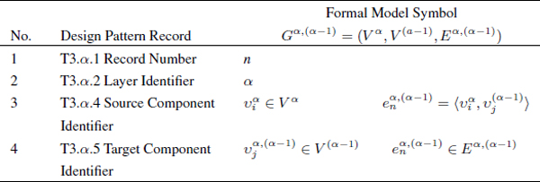
Table 3 Design pattern of intralayer topology specifications
| Table Columns | ||
| No. | Name | Description |
| 1 | T3.α.1 Record Number | Record identification number (projection index) |
| 2 | T3.α.2 Layer Identifier | Engineering (optional), physical, logical, service, social (optional) or functional layer (similar to T1.α.2 and T2.α.2) |
| 3 | T3.α.3 Projection Assignment | Components interlayer relation functional description (if necessary) |
| 4 | T3.α.4 Source Component Identifier | Component name according to T1.α.4 |
| 5 | T3.α.5 Target Component Identifier | Component name according to T1.α.4 |
| 6 | T3.α.6 Distribution Index | Cross-layer technologies: (1) Nn 1n-1 – virtualization and replication; (2) 1n Nn-1 – clustering; and (3) 1n 1n-1 – a special case of dedicated components |
| 7 | T3.α.7 Projection Attributes | Technical specifications of components interlayer relation (resources distribution across the network) technical specifications such as capacity metrics and modes (active/active, active/standby, etc. |
| 8 | T3. α.8 Notes | Additional information (if necessary) |
In turn, each table header structure should include: (1) Table Identifier; (2) Project Identifier; and (3) Facility Identifier.
In practice, these tables can be used (1) as independent documents or (2) as a database structure similar to ITU-T Rec L.72 [6].
4.2 Design Patterns and Formal Model Correlations
A model is any incomplete representation of reality – an abstraction [21]. In practice it means that design documentation usually contains much more data than we need to create models. In our case, from the perspective of the formal abstract model:
- The layer component specification is a node list (see Table 1): each row represents a node (vertex) in the graph and columns contain attributes (node labels). Data structures correlation between the formal model and this design pattern is shown in Table 4.
- The intralayer topology specification is an adjacency list or a relational table (see Table 2): each row represents an edge in the graph and columns contain incident (source and target) nodes among other attributes (edge labels). Data structures correlation between the formal model and this design pattern is shown in Table 5.
- The interlayer topology description is an adjacency list or a relational table (see Table 3): each row represents an edge in the graph and columns contain incident (source and target) nodes among other attributes. Data structures correlation between the formal model and this design pattern is shown in Table 6.
As mentioned above (see Section 3), the quality of formal methods based on abstract models is limited by the quality of these models. In the context of this work, complex network architecture can be unambiguously represented using a set of tables (design patterns) that should be included as a necessary part of the detailed design documentation of a computer network. In turn, this set of tables provides unambiguous definition of the formal model (3D graph) for analysis and verifying of the network structure (such as model-based testing (MBT) [40]). As a consequence, the human factor can be completely eliminated from the data transformation processes during the formal model generation activities – the process can be done in automated mode using the detailed design documentation as input data. In this case, the formal model is completely relevant to the design documentation (i.e. a trusted model from the viewpoint of network/system designers).
Table 4 Formal model and design pattern of layer component specifications
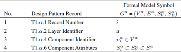
Table 5 Formal model and design pattern of intralayer topology specifications
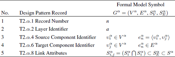
Figure 6 Formal model and design pattern of intralayer topology specifications
5 Approach Limitations
As the next step, it is important to highlight the following limitations of the proposed approach:
- The formal model based on the concept of multilayer networks is intended to specify heteroge-neous structures and their properties. The behavioral aspects of computer networks have to be described using different techniques (these aspects are beyond the scope of this work).
- The detailed design documentation should cover all coexisting architectural layers. Otherwise, the building (generation) of the formal model and, as a consequence, the application of the system methodology to network analysis is impossible.
- Based on Criterion 1 it is possible to detect the potential sources of primary (incorrect design) faults 5. The potential sources of secondary (incorrect requirements) and command faults (the behavioral aspects of computer networks) are beyond the scope of this work due to the properties of the formal model.
- Similar to other formal methods, the proposed approach has no future outlook without the support of standardization communities.
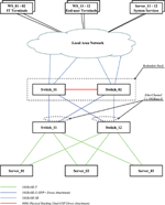
6 A Case Study
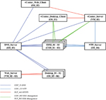
This case study is based on a pilot project which was used for the detailed acquaintance with VMware vSphere 6.0 virtualization platform [1].
The following figures represent architecture design for the following architectural layers 6:
- functional – see Figure 3;
- service – see Figure 4;
- logical – see Figure 5;
- physical – see Figure 6.
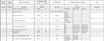
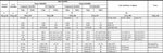
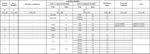
In turn, Figures 7–9 illustrate the examples of detailed design documentation – technical specifications – based on the predefined design patterns (see Section 4.1):

Figure 3 A Case Study – Functional architectural layer.
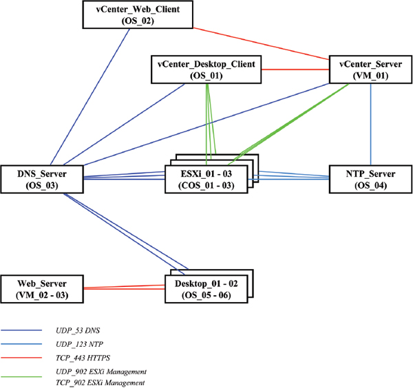
Figure 4 A Case Study – Service architectural layer.
- layer component specifications – see Figure 7;
- intralayer topology specifications – see Figure 8;
- interlayer topology specifications – see Figure 9.
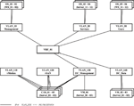
Finally, the multilayer model derived from the detailed design documentation is shown in Figure 10. It is important to note that the model generation process was a hands-off operation (i.e. the human factor was completely eliminated from the process) 7. In practice, this model was used for the following purposes:
- verification of the consistency of: (1) the formal model and, as a consequence, (2) the design documentation;
- automated generation of abstract test specifications (test cases).
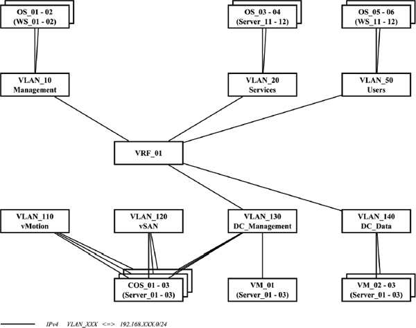
Figure 5 A Case Study – Logical architectural layer.
7 Conclusion
Formal methods based on abstract models are becoming more and more important in the domain of complex computer networks. On the other hand, processes of design documentation transformation into the formal models are still bound to the qualification and ingenuity of individual engineers. But in the case of complex or non-standard systems, personal experience and/or intuition can be inadequate. Moreover, the human work involved in data transformation represents a major bottleneck due to: (1) its tendency to be relatively unsophisticated and repetitive, but persistently tricky and time-consuming at the same time; and (2) the tendency of computer networks to be more and more complex. To address this problem, in this work we determined: (1) an appropriate formal model based on the concept of multilayer networks; and (2) a possible appropriate presentation format of architecture descriptions as a part of detailed design documentation (technical specifications) that provides unambiguous interrelation between the documentation and the model. In turn, the presentation format of this kind could allow automated development of multilayer formal models (including model consistency validation) for analysis and verifying of complex computer networks (i.e. computer networks and services/applications which these networks provide and support). As a consequence, (1) the formal model can be completely relevant to the design documentation (i.e. a trusted model from the viewpoint of network/system designers); and (2) the human factor can be completely eliminated from the model generation process. In turn, the formal model of this kind can be used for static and dynamic network analysis including structural test generation, security verifications, fault injection experiments, etc.
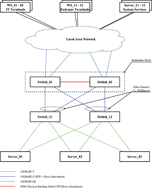
Figure 6 A Case Study – Physical architectural layer.
Figure 7 A Case Study – Example of Layer component specifications.
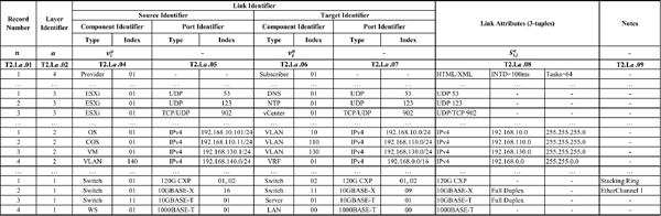
Figure 8 A Case Study – Example of Intralayer topology specifications.
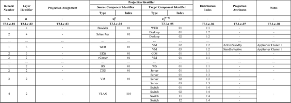
Figure 9 A Case Study – Example of Interlayer topology specifications.
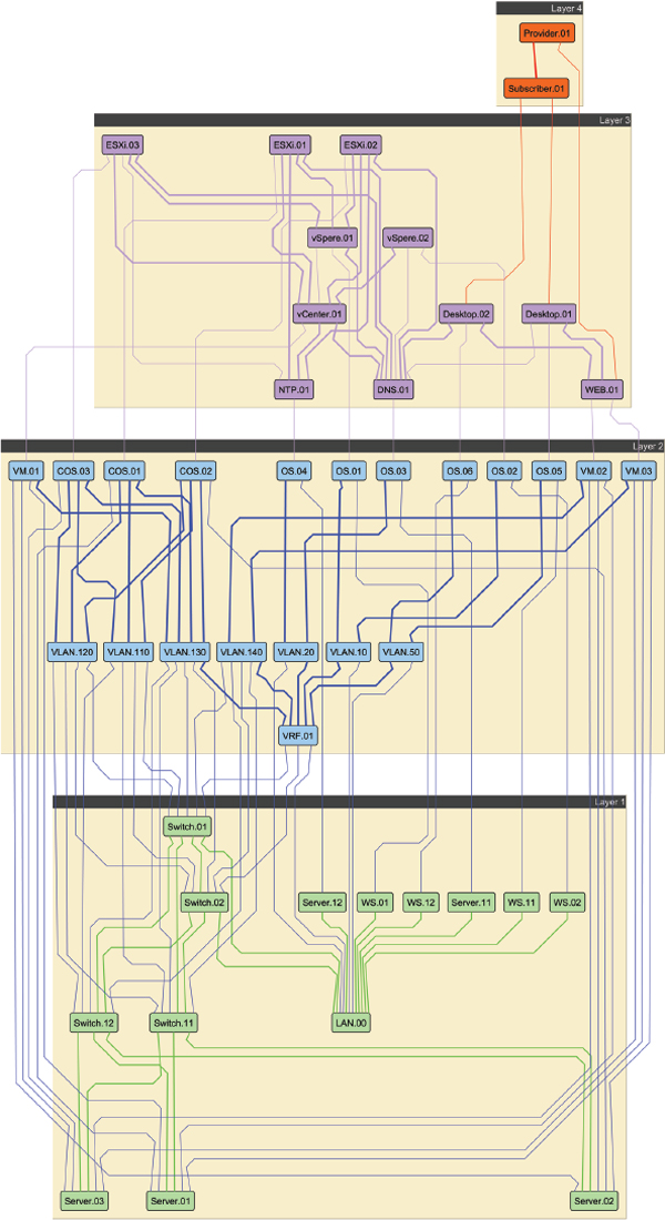
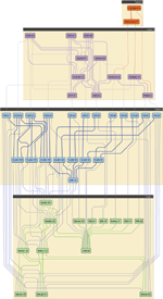
Figure 10 A Case Study – Multilayer model.
On the other hand, model-based techniques can be used for automated validation the formal model consistency with respect to the end-user requirements. In the case of successful validation, the formal model can be completely relevant to the end-user requirements (i.e. a trusted model from the viewpoint of end-users/customers). To accomplish such a goal, the formal operational specifications of end-user requirements should be based on the same presentation format that the technical specifications. However, the techniques of automated transforming of informal end-user requirements into formal operational specifications are beyond the scope of this work. The problem requires a separate analysis – even in the case of relatively simple systems, it may not be a routine exercise in practice 8. Nevertheless, a possible solution might lay in the domain of Artificial Intelligence – Ontological Engineering.
8 Acknowledgement
This article has originated within the project VI1VS/304 Comprehensive fiber optic sensor security of critical infrastructures and objects using modern information systems at the Department of Telecommunication Engineering (Czech Technical University in Prague, Faculty of Electrical Engineering).
References
[1] VMware vSphere.
[2] IETF RFC1122 – Requirements for Internet Hosts – Communication Layers, October 1989.
[3] IETF RFC1123 – Requirements for Internet Hosts – Application and Support, October 1989.
[4] ISO/IEC Std 7498-1:1994 – Information technology – Open Systems Interconnection – Basic Reference Model: The Basic Model, 1994.
[5] IEEE Std 1362-1998 (R2007) – IEEE Guide for Information Technology – System Definition – Concept of Operations (ConOps) Document, 2007.
[6] ITU-T Rec L.72 – Databases for optical access network infrastructure, 2008.
[7] ITU-T Rec Z.110-Z.119 – Application of formal description techniques, 2008.
[8] ISO/IEC/IEEE Std 24765:2010(E) – Systems and software engineering – Vocabulary, 2010.
[9] ISO/IEC Std 27005:2011 – Information technology – Security techniques – Information security risk management, 2011.
[10] ISO/IEC/IEEE Std 15289:2011 – Systems and software engineering – Content of life-cycle information products (documentation), 2011.
[11] ITU-T Rec Z.100-Z.109 – Specification and Description Language (SDL), 2011.
[12] ITU-T Rec Z.120-Z.129 – Message Sequence Chart (MSC), 2011.
[13] ITU-T Rec Z.150-Z.159 – User Requirements Notation (URN), 2011.
[14] ISO/IEC/IEEE Std 42010:2011 – Systems and software engineering – Architecture description, 2013.
[15] ITU-T Rec Z.160-Z.179 – Testing and Test Control Notation (TTCN), 2014.
[16] ISO/IEC/IEEE Std 15288:2015 – Systems and software engineering – System life cycle processes, 2015.
[17] Daniel Aceituna, Hyunsook Do, and Sudarshan Srinivasan. A syste- matic approach to transforming system requirements into model checking specifications. In Companion Proceedings of the 36th International Conference on Software Engineering (ICSE Companion 2014), pages 165–174, June 2014.
[18] Reka Albert and Albert-Laszlo Barabasi. Statistical mechanics of complex networks. Rev. Mod. Phys. 74(1):47–97, January 2002.
[19] Christopher Alexander, Sara Ishikawa, Murray Silverstein, Max Jacobson, Ingrid Fiksdahl-King, and Shlomo Angel. A Pattern Language: Towns, Buildings, Construction. Oxford University Press, 1977.
[20] S. Boccaletti, G. Bianconi, R. Criado, C.I. del Genio, J. Gomez-Gardenes, M. Romance, I. Sendina-Nadal, Z. Wang, and M. Zanin. The structure and dynamics of multilayer networks. Physics Reports 544(1):1–122, November 2014.
[21] Dennis M. Buede. The Engineering Design of Systems: Models and Methods. Wiley Publishing, 2nd edition, 2009.
[22] Douglas E. Comer. Internetworking With TCP/IP Volume I: Principles, Protocol, And Architecture. Pearson, 6th edition, 2015.
[23] Manlio De Domenico, Albert Sole-Ribalta, Emanuele Cozzo, Mikko Kivela, Yamir Moreno, Mason A. Porter, Sergio Gomez, and Alex Arenas. Mathematical formulation of multilayer networks. Phys. Rev. X, 3(4):041022, December 2013.
[24] Shaun L. Hummel. Cisco Design Fundamentals: Multilayered Design Approach for Network Engineers. Cisco Press, 1st edition, 2015.
[25] Sean Kandel, Andreas Paepcke, Joseph M. Hellerstein, and Jeffrey Heer. Enterprise data analysis and visualization: An interview study. IEEE Transactions on Visualization and Computer Graphics 18(12): 2917–2926, December 2012.
[26] Vladimir A. Khlevnoy and Andrey A. Shchurov. A formal approach to distributed system security test generation. International Journal of Computer Trends and Technology 16(3):121–127, October 2014.
[27] Mikko Kivela, Alex Arenas, Marc Barthelemy, James P. Gleeson, Yamir Moreno, and Mason A. Porter. Multilayer networks. Journal of Complex Networks 2(3):203–271, July 2014.
[28] Maciej Kurant and Patrick Thiran. Layered complex networks. Phys. Rev. Lett. 96(13):138701, April 2006.
[29] Maciej Kurant, Patrick Thiran, and Patric Hagmann. Error and attack tolerance of layered complex networks. Phys. Rev. E 76(2):026103, August 2007.
[30] James F. Kurose and Keith W. Ross. Computer Networking: A Top-Down Approach. Pearson, 6th edition, 2012.
[31] Nancy G. Leveson. Safeware: system safety and computers. ACM, 1995.
[32] Thomas A. Limoncelli, Christina J. Hogan, and Strata R. Chalup. The Practice of System and Network Administration. Addison Wesley, 2nd edition, 2007.
[33] James D. McCabe. Network Analysis, Architecture, and Design. Morgan Kaufmann, 3rd edition, 2007.
[34] Mark Newman. The structure and function of complex networks. SIAM Review 45(2):167–256, May 2003.
[35] Andrey A. Shchurov. A multilayer model of computer networks. International Journal of Computer Trends and Technology 26(1):12–16, August 2015.
[36] Andrey A. Shchurov and Radek Marik. A formal approach to distributed system tests design. International Journal of Computer and Information Technology 03(4):696–705, July 2014.
[37] Steven H. Strogatz. Exploring complex networks. Nature 410:268–276, March 2001.
[38] Andrew S. Tanenbaum and Maarten van Steen. Distributed Systems: Principles and Paradigms. Prentice Hall Press, 3rd edition, 2013.
[39] Andrew S. Tanenbaum and David J. Wetherall. Computer Networks. Prentice Hall Press, 5th edition, 2011.
[40] Mark Utting, Alexander Pretschner, and Bruno Legeard. A taxonomy of model-based testing approaches. Softw. Test. Verif. Reliab. 22(5): 297–312, August 2012.
[41] Russ White and Denise Donohue. The Art of Network Architecture: Business-Driven Design. Cisco Press, 1st edition, 2014.
[42] Ann Wong-Jiru. Graph Theoretical Analysis of Network-centric Operations Using Multilayer Models. BiblioScholar, 2012.
[43] Jim Woodcock, Peter Gorm Larsen, Juan Bicarregui, and John Fitzgerald. Formal methods: Practice and experience. ACM Comput. Surv. 41(4):19:1–19:36, October 2009.
Biographies

A. A. Shchurov, CCDP, CCNP, LPIC-2, is completing his dissertation toward a Ph.D. in telecommunication engineering at The Czech Technical University in Prague (Czech Republic). He has worked in information technology for the past 19 years as a senior system design engineer (HA telecommunication and network control systems for energy and chemical industries).

R. Marik, Ph.D., is a lecturer at The Czech Technical University in Prague (Czech Republic) and participated in research projects dealing with automated design in software testing, structural machine learning, and metaprogramming. He has worked in information technology for the past 25 years and he is a (co)-author of about 30 papers.
1 The terminology referring to systems with multiple different relations has not yet reached a consensus – different papers from various areas use similar terminologies to refer to different models, or distinct names for the same model.
2 For example in the case of security testing. In general, security testing should cover all threats defined by the current revision of ISO/IEC 27005:2011 standard [9]. However, this list of typical threats covers both aspects (software-based and network-based) of computing systems but not only these aspects.
3This appendix does not form an integral part of the Recommendation.
4The term design pattern [19] aims to explicitly represent design knowledge that can be understood implicitly by skilled engineers and other non-technical stakeholders.
5In the domain of computers: primary faults occur when errors result in the computer output not meeting its specification (incorrect design); secondary faults occur when the computer gets input that differ from what was anticipated or designed (incorrect requirements); and command faults occur when the computer responds to erroneous inputs that are expected but occur at the wrong time or in the wrong order [31].
6Environmental (optional) – engineering and social – layers are beyond the scope of this case study.
7The implementation details are beyond the scope of this work.
8Similar to Formal Description Techniques which require a considerable degree of user training for translating natural language requirements into their specialized language before applying model analysis.
Journal of ICT, Vol. 3, 201–230.
doi: 10.13052/jicts2245-800X.332
© 2016 River Publishers. All rights reserved.